1
Operating instructions
Object recognition sensor
UK
706225 / 00
11 / 2012
O2D22x
Object recognition sensor O2D22x
Contents
1 Preliminary note . . . . . . . . . . . . . . . . . . . . . . . . . . . . . . . . . . . . . . . . . . . . . . . . . . 4
1.1 Symbols used . . . . . . . . . . . . . . . . . . . . . . . . . . . . . . . . . . . . . . . . . . . . . . . 4
2 Safety instructions . . . . . . . . . . . . . . . . . . . . . . . . . . . . . . . . . . . . . . . . . . . . . . . . 4
3 Items supplied . . . . . . . . . . . . . . . . . . . . . . . . . . . . . . . . . . . . . . . . . . . . . . . . . . . 4
3.1 Accessories . . . . . . . . . . . . . . . . . . . . . . . . . . . . . . . . . . . . . . . . . . . . . . . . . 4
4 Functions and features . . . . . . . . . . . . . . . . . . . . . . . . . . . . . . . . . . . . . . . . . . . . 4
5 Installation . . . . . . . . . . . . . . . . . . . . . . . . . . . . . . . . . . . . . . . . . . . . . . . . . . . . . .
5.1 Mounting accessory . . . . . . . . . . . . . . . . . . . . . . . . . . . . . . . . . . . . . . . . . .
5.2 Mounting dimensions . . . . . . . . . . . . . . . . . . . . . . . . . . . . . . . . . . . . . . . . .
5.3 Installation location . . . . . . . . . . . . . . . . . . . . . . . . . . . . . . . . . . . . . . . . . . .
5
5
6
6
6 Electrical connection . . . . . . . . . . . . . . . . . . . . . . . . . . . . . . . . . . . . . . . . . . . . . . 7
6.1 Wiring . . . . . . . . . . . . . . . . . . . . . . . . . . . . . . . . . . . . . . . . . . . . . . . . . . . . . 7
6.2 Wiring . . . . . . . . . . . . . . . . . . . . . . . . . . . . . . . . . . . . . . . . . . . . . . . . . . . . . 8
6.3 External illumination . . . . . . . . . . . . . . . . . . . . . . . . . . . . . . . . . . . . . . . . . . 8
6.4 External trigger source . . . . . . . . . . . . . . . . . . . . . . . . . . . . . . . . . . . . . . . . 9
6.5 Timing diagrams . . . . . . . . . . . . . . . . . . . . . . . . . . . . . . . . . . . . . . . . . . . . 10
6.5.1 Inputs/outputs . . . . . . . . . . . . . . . . . . . . . . . . . . . . . . . . . . . . . . . . . . . . . 10
6.5.2 Static selection of the application . . . . . . . . . . . . . . . . . . . . . . . . . . . . . . 12
6.5.3 Pulse-controlled selection of the application . . . . . . . . . . . . . . . . . . . . . 13
7 Operating and display elements . . . . . . . . . . . . . . . . . . . . . . . . . . . . . . . . . . . .
7.1 LED display . . . . . . . . . . . . . . . . . . . . . . . . . . . . . . . . . . . . . . . . . . . . . . . .
7.2 Display . . . . . . . . . . . . . . . . . . . . . . . . . . . . . . . . . . . . . . . . . . . . . . . . . . . .
7.2.1 Operating indicators . . . . . . . . . . . . . . . . . . . . . . . . . . . . . . . . . . . . . . . .
7.2.2 Connection via the operating program . . . . . . . . . . . . . . . . . . . . . . . . . .
7.2.3 Error messages . . . . . . . . . . . . . . . . . . . . . . . . . . . . . . . . . . . . . . . . . . .
7.3 Pushbuttons . . . . . . . . . . . . . . . . . . . . . . . . . . . . . . . . . . . . . . . . . . . . . . .
14
14
15
15
16
16
16
8 Set-up . . . . . . . . . . . . . . . . . . . . . . . . . . . . . . . . . . . . . . . . . . . . . . . . . . . . . . . .
8.1 Parameter setting on the unit . . . . . . . . . . . . . . . . . . . . . . . . . . . . . . . . . .
8.2 Verify and set the IP address on the unit . . . . . . . . . . . . . . . . . . . . . . . . . .
8.3 Adjustable parameters . . . . . . . . . . . . . . . . . . . . . . . . . . . . . . . . . . . . . . . .
8.3.1 Parameter structure . . . . . . . . . . . . . . . . . . . . . . . . . . . . . . . . . . . . . . . .
8.4 Lock / unlock sensor . . . . . . . . . . . . . . . . . . . . . . . . . . . . . . . . . . . . . . . . .
8.4.1 Reset device to factory settings . . . . . . . . . . . . . . . . . . . . . . . . . . . . . . .
8.5 Parameter setting via PC operating program . . . . . . . . . . . . . . . . . . . . . .
17
17
17
18
19
20
20
20
9 Operation . . . . . . . . . . . . . . . . . . . . . . . . . . . . . . . . . . . . . . . . . . . . . . . . . . . . . . 21
9.1 Evaluation mode (normal operating mode) . . . . . . . . . . . . . . . . . . . . . . . . 21
10 Scale drawing . . . . . . . . . . . . . . . . . . . . . . . . . . . . . . . . . . . . . . . . . . . . . . . . . 21
11 Technical data . . . . . . . . . . . . . . . . . . . . . . . . . . . . . . . . . . . . . . . . . . . . . . . . . 22
11.1 Operating distance L . . . . . . . . . . . . . . . . . . . . . . . . . . . . . . . . . . . . . . . . 22
11.2 Factory settings . . . . . . . . . . . . . . . . . . . . . . . . . . . . . . . . . . . . . . . . . . . . 22
2
Object recognition sensor O2D22x
12 Process data protocol . . . . . . . . . . . . . . . . . . . . . . . . . . . . . . . . . . . . . . . . . . . 24
12.1 Configuring the process interface . . . . . . . . . . . . . . . . . . . . . . . . . . . . . . 24
12.2 Communication basics . . . . . . . . . . . . . . . . . . . . . . . . . . . . . . . . . . . . . . 24
12.2.1 Abbreviations and terms . . . . . . . . . . . . . . . . . . . . . . . . . . . . . . . . . . . . 24
12.2.2 Commands for the device . . . . . . . . . . . . . . . . . . . . . . . . . . . . . . . . . . 24
12.2.3 Replies from the device . . . . . . . . . . . . . . . . . . . . . . . . . . . . . . . . . . . . 24
12.3 Protocol versions . . . . . . . . . . . . . . . . . . . . . . . . . . . . . . . . . . . . . . . . . . . 25
12.4 Command types . . . . . . . . . . . . . . . . . . . . . . . . . . . . . . . . . . . . . . . . . . . 25
12.5 Release trigger . . . . . . . . . . . . . . . . . . . . . . . . . . . . . . . . . . . . . . . . . . . . 26
12.6 Select protocol version . . . . . . . . . . . . . . . . . . . . . . . . . . . . . . . . . . . . . . 26
12.7 Select the application . . . . . . . . . . . . . . . . . . . . . . . . . . . . . . . . . . . . . . . 26
12.8 Activate/deactivate result output . . . . . . . . . . . . . . . . . . . . . . . . . . . . . . . 27
12.9 Transmit the image to the device for evaluation . . . . . . . . . . . . . . . . . . . 27
12.10 Transmit the application data set to the device . . . . . . . . . . . . . . . . . . . 28
12.11 Request the assignment of the application data from the device . . . . . 28
12.12 Request the statistics from the device . . . . . . . . . . . . . . . . . . . . . . . . . . 29
12.13 Request the error code from the device . . . . . . . . . . . . . . . . . . . . . . . . 29
12.14 Request the last image from the device . . . . . . . . . . . . . . . . . . . . . . . . 29
12.15 Request the last result from the device . . . . . . . . . . . . . . . . . . . . . . . . . 30
12.16 Release trigger, evaluate captured image and result output via process
interface . . . . . . . . . . . . . . . . . . . . . . . . . . . . . . . . . . . . . . . . . . . . . . . . . . . . . . 30
12.17 Request the protocol version . . . . . . . . . . . . . . . . . . . . . . . . . . . . . . . . . 30
12.18 Request the device information . . . . . . . . . . . . . . . . . . . . . . . . . . . . . . . 31
12.19 Request the last "bad" image from the device . . . . . . . . . . . . . . . . . . . 31
12.20 Result message . . . . . . . . . . . . . . . . . . . . . . . . . . . . . . . . . . . . . . . . . . . 32
12.21 Error codes from the device . . . . . . . . . . . . . . . . . . . . . . . . . . . . . . . . . 35
13 Maintenance, repair and disposal . . . . . . . . . . . . . . . . . . . . . . . . . . . . . . . . . . 37
14 Approvals/standards . . . . . . . . . . . . . . . . . . . . . . . . . . . . . . . . . . . . . . . . . . . . 37
15 Note on the software . . . . . . . . . . . . . . . . . . . . . . . . . . . . . . . . . . . . . . . . . . . . 37
3
UK
Object recognition sensor O2D22x
1 Preliminary note
1.1 Symbols used
►
Instruction
>
Reaction, result
[…]
Designation of pushbuttons, buttons or indications
→
Cross-reference
Important note
Non-compliance can result in malfunction or interference
Information
Supplementary note
2 Safety instructions
These instructions are part of the device. They contain information and illustrations
about the correct handling of the device and must be read before installation or
use.
Observe the operating instructions.
Non-observance of the instructions, operation which is not in accordance with use
as prescribed below, wrong installation or incorrect handling can affect the safety
of operators and machinery.
The installation and connection must comply with the applicable national and international standards. Responsibility lies with the person installing the unit.
Only the signals indicated in the technical data or on the device label may be supplied to the connections or wires.
3 Items supplied
1 Object recognition sensor O2D22x
1 Operating instructions "Object recognition sensor O2D22x”, Ident no.: 706225
The device is supplied without installation/connection accessories and software.
3.1 Accessories
www.ifm.com
→ Data sheet search → e.g. O2D220 → Accessories
4 Functions and features
The sensor uses incident light or backlight to detect the contours of an object and
compares them with the contours of one or several models in a reference image.
Depending on the degree of conformity the output can indicate if a model was
found or which one was found.
4
Object recognition sensor O2D22x
5 Installation
5.1 Mounting accessory
The device is compatible with the mounting accessories of ifm's photoelectric sensors for the O2Ixxx (multicode reader), O2Mxxx (EthernetCamera) series etc.
Example mounting with clamp and bracket
►► Use the mounting accessory E2D101.
UK
1. Focal setter
2. Mounting accessory
3. Object to be recognised
4. Field of view size W X H
5. Operating distance L
Depending on the intended location and type of mounting the following mounting
accessories are available:
Description
Art. no.
Mounting set for shaft Ø 12 mm
(clamp and bracket for types O2Dxxx, O2Mxxx, O2Ixxx)
E2D110
Shaft, straight Ø 12 mm, length 130 mm, M10
E20938
Shaft, angled Ø 12 mm, length 200 mm, M10
E20940
Mounting set for shaft Ø 14 mm
(clamp and bracket for types O2Dxxx, O2Mxxx, O2Ixxx)
E2D112
5
Object recognition sensor O2D22x
Description
Art. no.
Shaft, straight Ø 14 mm, length 130 mm, M12
E20939
Shaft, angled Ø 14 mm, length 200 mm, M12
E20941
You can find more information about the available accessories at:
www.ifm.com → Data sheet search → e.g. O2D220 → Accessories
or directly
www.ifm.com → Data sheet search → e.g. E2D110
5.2 Mounting dimensions
The device is mounted using the mounting accessories or 2 M4 screws and nuts.
Hole dimensions → Chapter 10 Scale drawing.
5.3 Installation location
►► Mount the sensor in front of or above the area to be monitored.The detectable
field of view size depends on the operating distance → Chapter 11 Technical
Data.
►► Back light or scattered light situations and continuously changing light conditions are to be avoided.
►► Do not position room lights directly facing the camera lens.
►► Position the optional external illumination (e.g. O2D909) opposite the camera
lens.
►► To avoid adverse effects on the image detection, avoid installation in heavily
polluting areas of the machine.
►► The connected cables must be provided with a strain relief.
6
Object recognition sensor O2D22x
6 Electrical connection
NOTE
The unit must be connected by a qualified electrician. Disconnect power before
connecting the unit.
6.1 Wiring
Process interface (1)
UK
M12 plug, A-coded, 8 poles (view on the unit)
1U+
2 Trigger input
30V
4 Switching output / trigger output
5 Switching output (ready)
6 Switching output (OUT)
7 Switching output / input 1
8 Switching output / input 2
Parameter/process interface (2)
M12 socket, D-coded, 4 poles (view on the unit)
1 Ethernet TD +
2 Ethernet RD +
3 Ethernet TD 4 Ethernet RD SShield
7
Object recognition sensor O2D22x
6.2 Wiring
A: Process interface
B: Controller e.g. PLC
D
C: External trigger
D: External illumination
(optional)
Pin
5
6
A
C
B
Use (factory setting)
Output signal "READY" provides the status of the sensor:
"1" after the evaluation has been carried out. "0" as long as the evaluation is being carried out, a
different application is being selected or in case of an internal error (trigger signals are ignored).
Output signal "OUT" provides the result of the evaluation:
"0" no matching model "1" matching model
►► For PNP units (e.g. O2D220) use trigger sensors, illumination units and controllers with PNP inputs and outputs.
►► For NPN units (e.g. O2D227) use trigger sensors, illumination units and controllers with NPN inputs and outputs.
6.3 External illumination
►► Connect external illumination to the trigger output of the device.
Example
Art. no.
Illumination unit, transmitter red light 630 nm
O2D909
For information about the a.-m. example see:
www.ifm.com → Data sheet search → O2D909
8
Object recognition sensor O2D22x
6.4 External trigger source
►► Connect an external trigger source (e.g. a diffuse reflection sensor) to the trigger input of the device.
If you use an external trigger source (e.g. a diffuse reflection sensor),
connect the trigger signal to the trigger input of the sensor. If you use external illumination, it must be controlled via the trigger output of the sensor.
Depending on the device setting, one of four configuration files saved in the
sensor can be selected via two switching inputs. Information about the test
result is provided via switching outputs.
UK
9
Object recognition sensor O2D22x
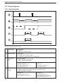
6.5 Timing diagrams
6.5.1 Inputs/outputs
4.1
4.2
Example: Triggering positive edge
1:
Trigger input
Trigger signal
0: no action
1: triggering on positive edge
2:
READY output
Ready signal
0: unit busy, OUT output not valid
1: unit ready for trigger signal, OUT output valid
3:
OUT output,
static
Object evaluation
0: object evaluation not successful
1: object evaluation successful
Example 1 (dashed line):
last object OK, OUT = 1
next object faulty, OUT 1 → 0
next object OK, OUT 0 → 1
4
OUT output,
pulsed
Object evaluation
0: object evaluation not successful or timeout of pulse length
1: object evaluation successful
Example 4.1:
both objects OK, OUT = 1
after expiration of tB, OUT = 0
10
Example 2 (solid line):last object faulty,
OUT = 0
next object OK, OUT 0 → 1
next object OK, OUT 1
Example 4.2:
first object OK, OUT = 1
after expiration of tB, OUT = 0
second object faulty, OUT = 0
Object recognition sensor O2D22x
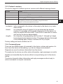
The evaluation time tA depends on
●● the size of the field of view selected
●● the model size
●● the smoothing degree
●● the sensitivity
●● the orientation
●● the number of models
UK
Typical evaluation times are between 50 and 800 ms.
The pulse length tB can be set between 100 ms and 2000 ms via the PC user
program. For more detailed information about the configuration of the switching
outputs we refer you to the programming manual of the sensor.
www.ifm.com
→ Data sheet search → O2D220 → Operating instructions
11
Object recognition sensor O2D22x
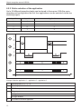
6.5.2 Static selection of the application
Up to 32 different inspection tasks can be stored in the sensor. With the corresponding unit configuration the first four applications can be selected via the two
switching inputs.
Input 2
Input 1
Application no.
0
0
1
0
1
2
1
0
3
1
1
4
1
0
R
R
1
0
1
0
1
-
2
-
3
t
Example: Selection application 1 → application 2 → application 3
1:
Switching input 1 = 0 → 1 → 0
2:
Switching input 2 = 0 → 0 → 1
3:
READY output
4:
Trigger input
A: trigger enabled
B: trigger disabled
5:
12
ID number of the active application
Object recognition sensor O2D22x
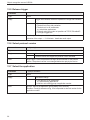
For the selection of the applications the monitoring time tR and the trigger disable
time tP have to be taken into consideration.
Monitoring time tR: After a change in edges the external selection of the application
does not start before the state of both switching inputs remains stable for 20 ms.
Trigger disable time tP: The trigger input is disabled during the selection of the
application. The disable time depends on:
●● the number of applications on the sensor
●● the number of models in the application to be activated
UK
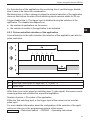
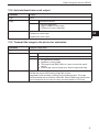
6.5.3 Pulse-controlled selection of the application
As an alternative to the static selection the selection of the application can also be
pulse-controlled.
1
2
3
4
5
1:
Gate signal, switching input 1 = 0 → 1 → 0 (tG = signal active)
2:
Pulse signal, switching input 2 or trigger input = 0 → 5 pulses → 0
3:
READY output
While there is an active signal on switching input 1 (gate signal), the sensor counts
incoming pulses and activates the respective application.
Number of pulses = ID number of the application
Either the 2nd switching input or the trigger input of the sensor can be used as
pulse input.
For more detailed information about the configuration of the selection of the application we refer you to the programming manual of the sensor.
www.ifm.com → Data sheet search → O2D220 → Operating instructions
13
Object recognition sensor O2D22x
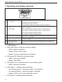
7 Operating and display elements
1
2
3
4
5
Active LED
Power (ready for operation display)
Eth (Ethernet connection status)
Con (connection status to the operating program (software))
Indication of the switching status; lights when the corresponding input or
output is switched.
LED 1 status indication switching output 1 / switching input 1
4 x LED yellow
LED 2 status indication switching output 2 / switching input 2
LED 3 status indication switching output 3
LED 4 status indication switching output 4
Indication of the evaluation results, parameters, parameter values, war4-digit alphanumeric display
nings and error messages.
Setting of the parameter values (scrolling by holding pressed; incremental
Programming button "Set"
by pressing briefly).
Programming button
Selection of the parameters and acknowledgement of the parameter
Mode / Enter
values.
3 x LED green
7.1 LED display
●● LED green Power: ready for operation display
–– lights: ready for operation
–– flashes (20 Hz): device fault
–– flashes (2 Hz): no application on the device
●● LED green Eth: Ethernet connection status
–– lights: connection available
–– flashes: data traffic
●● LED green Con: connection status to operating program
–– lights: connection available
●● LED yellow 1: switching status indication
–– off: switching input 1 / switching output 1 not switched
–– on: switching input 1 / switching output 1 switched
–– flashes (20 Hz): short circuit switching output 1
●● LED yellow 2: switching status indication
14
Object recognition sensor O2D22x
–– off: switching input 2 / switching output 2 not switched
–– on: switching input 2 / switching output 2 switched
–– flashes (20 Hz): short circuit switching output 2
●● LED yellow 3: switching status indication
–– off: switching output 3 not switched
–– on: switching output 3 switched
–– flashes (20 Hz): short circuit switching output 3
UK
●● LED yellow 4: switching status indication
–– off: switching output 4 not switched
–– on: switching output 4 switched
–– flashes (20 Hz): short circuit switching output 4
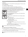
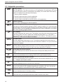
7.2 Display
7.2.1 Operating indicators
Display
Description
vNNN
Version number of the IO controller software
(1st indication after power on, e. g. v041)
Init
Device initialisation after power on
(2nd indication after power on)
nnnn
Firmware version, e.g. 1031
(3rd indication after power on)
rEdY
Device ready for trigger
(4th indication after power-on if one configuration is active with external triggering.
Device waiting for triggering.)
WAIT
Device is busy
nr28
Application successful (number of the application)
run
Device waiting for connection, no application active (factory setting)
LOAd
Loading an application
donE
Loading of application completed
uLoc
Keys unlocked
Parameter values can be displayed and changed
Lock
Locking the pushbuttons
Lok1
Pushbuttons locked
FWUP
Firmware update running
15
Object recognition sensor O2D22x
7.2.2 Connection via the operating program
Display
Description
OnLI
Connection with the operating program
Parm
Parameter setting via operating program
Moni
Monitor mode
SerP
Connection with the operating program, service report mode
7.2.3 Error messages
Display
Description
FAIL
Application not successful
ErrD
Critical hardware error
ErrP
Selection of a non-existing application via switching inputs
SC
Short circuit of a switching output
DHCP_noIP
No DHCP server found. Both character strings are displayed alternately.
7.3 Pushbuttons
Button
Function
MODE/ENTER
Change into the parameter setting mode
Selection of the parameters
Acknowledgement of the parameter values
SET
Selecting the subparameters
Setting/changing/selecting the parameter values
- incremental by pressing briefly
- hold down to scroll
16
Object recognition sensor O2D22x
8 Set-up
Set-up is carried out via a menu-guided PC operating program. The device stores
up to 32 applications.
8.1 Parameter setting on the unit
Set the parameter values via pushbuttons and display on the device.
The sensor is programmed using the two buttons [Mode/Enter] and [Set].
First activate a parameter with the [Mode/Enter] button, select the required value
with the [Set] button and confirm it pressing again the [Mode/Enter] button.
The unit changes to the parameter setting mode when you
UK
►► press [MODE/ENTER] for more than 1 s.
>> The first menu item is displayed.
►► Press [MODE/ENTER] several times until the required parameter is displayed.
►► Press [SET].
►► The menu item is activated and the current setting is displayed.
►► Keep [SET] pressed.
>> The display flashes, after 5 s with pressed SET button the
display stops flashing.
►► Press [SET] and change setting.
►► Press [Mode/Enter].
>> The change is acknowledged and the previous menu item is
shown again.
If no button is pressed for longer than 15 s, you will get to the next
higher menu item or the evaluation mode.
The device does not operate during use of the pushbuttons.
8.2 Verify and set the IP address on the unit
►► Select the parameter "IP" (IP address) with [MODE/ENTER] and [SET].
>> The IP address is processed automatically and shown in 4 groups (A, B, C, D).
►► Verify the IP address and set with [SET], if necessary.
Changes only become effective after a restart of the unit (power off, power
on).
17
Object recognition sensor O2D22x
8.3 Adjustable parameters
Memory location
Select an application. The device can save up to 32 applications. By pressing the SET button
the memory location number is incremented in the display. The current state of the memory
location is visualised in the first digit of the display:
F = memory location available
I = memory location used by an inactive application
A= memory location used by an active application
E = memory location (selected by external selection of the application)
Network operation
Here you set the parameters for network operation.
Network settings via DHCP
If the sensor is to get its network settings via DHCP, select the setting "on" in this menu item.
With the setting "off" the fixed network settings (see next menu items) are used. In the DHCP
mode the sensor must be operated in a network with DHCP server. Otherwise it is not accessible via the operating program E2D200.
Set IP address
Here the IP address of the sensor is set. This setting is used when the sensor does not work
in the DHCP mode.The input is made in the "dotted decimal notation", e.g. 192.168.0.3.
Using the SET button you can select the four groups of the address. The respective group is
visualised by a letter in the first digit of the display.
Set subnet mask
Here the subnet mask of the sensor is set. This setting is used when the sensor does not
work in the DHCP mode.The subnet mask must match the IP address. It is input in the same
way as the IP address.
Set gateway address
Here the gateway address used by the sensor is set. This setting is used when the sensor
does not work in the DHCP mode. It is input in the same way as the IP address.
Set the Ethernet process interface
Here the Ethernet process interface and the version of the process data protocol are selected.
Select the Ethernet process interface
Here you choose between the two settings TCP/IP (TCP) and EtherNet/IP (EIP).
Select the process data protocol version
Here you choose between the four possible versions of the process data protocol (v1, v2, v3,
v4). → Chapter 12.3 Protocol versions.
Access extended functions
Here the extended functions of the sensor are accessed.
Rotate / switch off display
Here you set whether a text is displayed normally (d) or rotated by 180° (rd). You also set
whether the display is to be switched off (oFF) in the evaluation mode.
Reset sensor
Here you reset the sensor to the factory setting.
Firmware version
In this menu item you can enquire about the firmware version of the sensor.
18
Object recognition sensor O2D22x
8.3.1 Parameter structure
UK
PCIS
IF
TCP
TCP
EIP
PrOT
v2
v2
v3
v4
v1
19
Object recognition sensor O2D22x
8.4 Lock / unlock sensor
Lock sensor
►► Keep [Mode/Enter] and [Set] pressed simultaneously for 10 s.
>> Display changes to uLok.
►► Press [Set].
►► Display changes to Lock.
►► Confirm with [Mode/Enter].
>> The sensor is locked.
Unlock the sensor
►► Keep [Mode/Enter] and [Set] pressed simultaneously for 10 s.
>> Display shows Lok1, changes to Lock after 10 s.
►► Press [Set].
>> Display changes to uLok.
►► Confirm with [Mode/Enter].
The sensor is unlocked, display changes to "run".
8.4.1 Reset device to factory settings
►► Activate the parameter "rES".
►► Press [SET] > 5 s.
8.5 Parameter setting via PC operating program
The PC operating program is described in a separate document → Programming
manual E2D200.
www.ifm.com
20
→ Data sheet search → Additional data
Object recognition sensor O2D22x
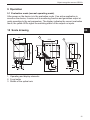
9 Operation
9.1 Evaluation mode (normal operating mode)
After power-on the device is in the evaluation mode. If an active application is
saved on the device, it carries out its monitoring function and generates output signals according to the set parameters. The display indicates the current evaluation
result, the yellow LEDs signal the switching status of the outputs or inputs.
UK
10 Scale drawing
1. Operating and display elements
2. Focal setter
3. Middle of the optical axis
21
Object recognition sensor O2D22x
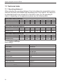
11 Technical data
11.1 Operating distance L
When selecting the operating distance it has to be taken into account that contour
detection becomes less reliable with decreasing size of the objects. The objects to
be detected should cover at least 5% of the field of view. For the operating distance L depending on the applications please see the following table.
Types O2D220 / O2D227 (normal lens)
Operating distance L [mm]
50
Field of view size WxH [mm]
16x12
Resolution [mm]
0.1
75
24x18
0.2
100
32x24
0.3
200
64x48
0.4
400
128x96
0.8
1000
320x240
2.0
2000
640x480
4.0
Types O2D222 / O2D229 (wide-angle lens)
Operating distance L [mm]
50
Field of view size WxH [mm]
33x24
Resolution [mm]
0.3
75
50x36
0.4
100
66x47
0.5
200
132x94
0.9
400
264x189
1.7
1000
660x472
4.0
2000
1320x945
8.0
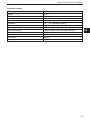
Types O2D224 / O2D225 (telephoto lens)
Operating distance L [mm]
50
Field of view size WxH [mm]
Resolution [mm]
-
75
15x11
0.08
100
20x15
0.12
200
40x30
0.25
400
80x60
0.52
1000
200x150
1.25
2000
400x300
2.52
11.2 Factory settings
Device settings
Parameters
Device name
Device location
DHCP
IP address
Subnet mask
Gateway
XML-RPC port
Video port
Application selection via switching inputs
Trigger debouncing
Process interface mode
Process interface version
Process interface TCP/IP port
22
Factory setting
New sensor
New location
not active
192.168.0.49
255.255.255.0
192.168.000.201
8080
50002
not active
not active
TCP/IP
2
50010
Object recognition sensor O2D22x
Application settings
Parameters
Models
Minimum match
Contour tolerance width
Number of models
Orientation
Device connection 4
Device connection 5
Device connection 6
Device connection 7
Device connection 8
Illumination
Trigger mode
Factory setting
none
80%
4
1
-10°... +10° (operating program)
Trigger output (with external illumination)
Switching output, function ready for trigger (Ready)
Switching output, function all models detected
Internal
Continuous
UK
23
Object recognition sensor O2D22x
12 Process data protocol
The process interface ensures communication between the process PC (e.g. PLC)
and the device. A command from the process PC can for example activate trigger
pulses, select applications or provide application results.
12.1 Configuring the process interface
When the Ethernet interface is used, two protocols are available: TCP/IP and
EtherNet/IP. The protocol is selected and configured in the PC operating program.
For more detailed information about the configuration of the process interface we
refer you to the programming manual of the sensor.
www.ifm.com
→ data sheet search → O2D220 → Operating instructions
12.2 Communication basics
12.2.1 Abbreviations and terms
Abbreviation
Description
ASCII code (dec)
CR
Carriage Return
13
LF
Linefeed
10
<>
Marking of a placeholder (e.g. <code> is a placeholder for code)
[]
Optional argument (possible but not required)
12.2.2 Commands for the device
●● 8-bit ASCII characters are allowed.
●● All commands to the device are terminated with an LF character.
The device ignores all received CR characters.
●● A command to the unit has to be transmitted within 5 s.
Otherwise the unit will cancel command recognition.
12.2.3 Replies from the device
●● All replies by the device are terminated with an CR and an LF character.
●● As a reply to a valid command the device provides the character string
* CR LF (ASCII 42 dec + 13 dec + 10 dec).
●● As a reply to an invalid command the device provides the character string
? CR LF (ASCII 63 dec + 13 dec + 10 dec).
●● If the device is busy, it provides the character string
! CR LF (ASCII 33 dec + 13 dec + 10 dec) as a reply.
24
Object recognition sensor O2D22x
12.3 Protocol versions
The device supports 4 different protocol versions with different message format.
Version
Format
V1
<contents>CR LF
V2
<ticket><contents>CR LF
V3
<ticket><length>CR LF<ticket><contents>CR LF
V4
<length>CR LF<contents>CR LF
The replies by the device are preceded by length information;
however, not the commands to the device.
UK
<contents> is the command to the device or the reply by the device (e.g. evaluation results).
<ticket>
is a character string of 4 digits 0-9, to be interpreted as decimal
number. If a message with a specific ticket is sent to the device, its
reply will contain the same ticket. Ticket 0000 is reserved for messages sent by the device independently.
<length>
is a character string beginning with the letter 'L' followed by 9 digits
to be interpreted as decimal number. This figure indicates the length
of the following data (<ticket><contents>CR LF) in bytes.
Factory setting and reset condition are V2.
12.4 Command types
There are two different types of command to the device: actions and queries. Actions have the device do something, e.g. take an image and evaluate it.
Requests are used to retrieve information from the device.
The replies by the device are either status information, reply messages or results.
Results are transmitted by the device without a request being sent to the device
before.
The device transmits status information and reply messages as direct reply to
action commands or request commands.
25
Object recognition sensor O2D22x
12.5 Release trigger
Command
t
Type
Action
Reply
*
Trigger was released, the device captures the image and evaluates
it.
!
●● Currently no application active.
●● The device is busy with evaluation.
●● The device is in an invalid state,
e.g. administer applications.
●● Currently set trigger mode not possible via TCP/IP; EtherNet/IP
●● Too high a trigger rate
Note
Result output via the process interface if the output is activated.
Activation of the output → 12.8 Activate / deactivate result output.
12.6 Select protocol version
Command
v <digit><digit>
Type
Action
Reply
*
Normal case
!
The device does not support the protocol version indicated.
Note
<digit><digit>: to be interpreted as two-digit decimal number for the protocol
version. The protocol version is not changed before the reply by the device.
12.7 Select the application
Command
c <group><number>
Type
Action
Reply
*
Successful change
!
●● The device is in an invalid state,
e.g. administering applications.
●● Invalid or not existing group or application number.
Note
26
<group>: digit for the application group (always 0 for O2D22X).
<number>: two-digit character string, to be interpreted as decimal number for the
application number.
Object recognition sensor O2D22x
12.8 Activate/deactivate result output
Command
p <digit>
Type
Action
Reply
*
Successful execution
!
●● No active application.
●● <digit> contains incorrect value.
●● The device is in an invalid state.
Note
<digit> is either 0 or 1.
1 enables the result output.
0 disables the result output.
UK
12.9 Transmit the image to the device for evaluation
Command
i <length><image data>
Type
Action
Reply
*
Normal case
?
Invalid length
!
●● No application at present.
●● Application is being edited.
●● The image format (BMP, RAW, etc.) does not meet the specifications.
●● Invalid image contents (image size, internal image head data).
Note
<length>: character string with exactly 9 digits, interpreted as decimal number it
indicates the length of the following image data in bytes.
Image data format according to setting in the operating program. The image
must be available with a resolution of 640x480. With the Raw image format, each
pixel is coded with an 8 bit value, the bmp must be available in 8 bit format.
27
Object recognition sensor O2D22x
12.10 Transmit the application data set to the device
Command
u <length><group><number><application data set>
Type
Action
Reply
*
Normal case
?
Invalid length
!
●● The device is in teach mode or in administrative mode.
●● <application data set> is no valid application.
●● The group/application number is invalid.
●● "Selection of the application" via digital switching inputs is
activated.
Note
<length>: character string with exactly 9 digits, interpreted as decimal number it
indicates the length of the following image data in bytes (file length + 3 for group
and number).
<group>: digit for the application group (always 0 for O2D22X).
<number>: two-digit character string, to be interpreted as decimal number for the
application number.
12.11 Request the assignment of the application data from the device
Command
a?
Type
Request
Reply
<number><blank><group><number><blank><group>
<number><blank>...<group><number>
Normal case
!
No application active on
the device.
Note
28
<number>: character string with 3 digits for the number of applications on the
device as decimal number.
<group>: digit for the application group (always 0 for O2D22X).
<number>: two-digit character string, to be interpreted as decimal number for the
application number.
At first the number of the active configuration is output.
<blank>: individual blank.
Object recognition sensor O2D22x
12.12 Request the statistics from the device
Command
s?
Type
Request
Reply
<total><blank><good><blank><bad>
Normal case
!
No application active on
the device.
Note
<total>: total number of evaluations.
<good>: number of "good" evaluations.
<bad>: number of "bad" evaluations.
<blank>: individual blank.
<total>, <good> and <bad> are always character strings with 10 digits, to be
interpreted as decimal number.
UK
12.13 Request the error code from the device
Command
E?
Type
Request
Reply
<code>
Note
<code> is the error code, character string with 4 digits, to be interpreted as
decimal number.
Chapter Error codes 12.21
12.14 Request the last image from the device
Command
I?
Type
Request
Reply
<length><image data>
Normal case
!
●● Currently no application active.
●● No evaluation carried out.
●● Sensor is working.
Note
<length>: character string with exactly 9 digits, interpreted as decimal number it
indicates the length of the following image data in bytes.
Image data format according to setting in the operating program.
29
Object recognition sensor O2D22x
12.15 Request the last result from the device
Command
R?
Type
Request
Reply
Message in result format
→ Chapter result message 12.20.
Normal case
!
●● Currently no application active.
●● Application is being edited.
●● No results availabe yet.
Note
none
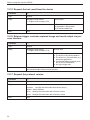
12.16 Release trigger, evaluate captured image and result output via process interface
Command
T?
Type
Request
Reply
Message in result format
→ Chapter result message 12.20.
Normal case.
!
●● Currently no application active.
●● The device is busy with evaluation.
●● The device is in an invalid state, e.g.
administer applications.
●● Currently set trigger mode not possible via TCP/IP; EtherNet/IP
●● too high a trigger rate
Note
The result is always provided via the process interface; with activated and also
non-activated output via the process interface.
12.17 Request the protocol version
Command
V?
Type
Request
Reply
<current><blank><min><blank><max>
<current> two-digit decimal number with current version
<blank> space character
<min> two-digit decimal number with minimum version
<max> two-digit decimal number with maximum version
Note
none
30
Object recognition sensor O2D22x
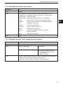
12.18 Request the device information
Command
D?
Type
Request
Reply
<manufacturer><t><article number><t><name><t><location><t><ip>
<subnet mask><t><gateway><t><MAC><t><DHCP><t><port number>
<manufacturer> IFM ELECTRONIC
<article number>article designation and status, e.g. O2D220AC
<name>
sensor name as entered in the operating program
<location>
sensor location as entered in the operating program
<ip>
IP address of the device
<subnet>
subnet mask of the device
<gateway>
gateway address of the device
<MAC>
MAC address of the device
<DHCP>
0 if DHCP is disabled, 1 if DHCP is enabled
<t>tabulator character
<port>
XML-RPC port number
Note
UK
none
12.19 Request the last "bad" image from the device
Command
F?
Type
Request
Reply
<length><image data>
Normal case
!
●● Currently no application active.
●● No evaluation carried out or no
error occurred.
●● Sensor is working.
Note
<length>: character string with exactly 9 digits, interpreted as decimal number it
indicates the length of the following image data in bytes.
Image data format according to setting in the operating program.
31
Object recognition sensor O2D22x
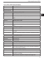
12.20 Result message
The evaluation result can be provided in ASCII or binary format. The output format
is set via the PC operating program.
ASCI format
In the ASCII mode the evaluation result is transmitted in the following format:
<start><result><sc><match><sc><instances>[<sc><model info>][<sc><image
info>]<stop>
Component
Description
<start>
Start string according to setting in operating program.
<sc>
Separator according to setting in the operating program.
<stop>
Stop string according to setting in operating program.
<result>
Total result, either 'PASS' or 'FAIL' string.
<match>
Overall match quality, in the format <digit><digit><digit>.<digit>, for example
‘089.5’ for 89.5% match.
The "overall match quality" corresponds to the object with the worst match.
<instances>
Character string with 3 digits (decimal number) for the number of objects found
(instances).
[<model info>]
Optional detailed information, only if object detail output has been enabled in the
operating program.
Format:
<model_index><sc><x><sc><y><sc><rot><sc><match_quality>
[<image info>]
32
<model_index>
Two-digit model number
<x>
Character string with 4 digits, decimal number for X position
of the object (in pixels); zero point left
<y>
Character string with 4 digits, decimal number for Y position
of the object (in pixels); zero point top
<rot>
Character string with six characters for the orientation of the
object
e.g. +179.0 or –001.3
<match_quality>
Match quality, in the format
<digit><digit><digit>.<digit>, for example ‘089.5’ for an 89.5%
match.
Optional image information only if image output in the operating program has
been enabled.
Format:
<format><sc><length><sc><image data>
<format>
‘RAW’ or ‘BMP’ according to the setting of the image format
in the operating program.
<length>
9-digit decimal number for the quantity of image data in
bytes
<image data>
Image data in the given format
Object recognition sensor O2D22x
Binary format
In the binary mode the evaluation result is transmitted in the following format:
<start byte>< switching outputs><match><instances>[<model info>]
Component
Description
<start byte>
Start byte: 0x00 (1 byte)
<switching outputs>
Status of the switching outputs (SA) after the evaluation
binary value (2 bytes, unsigned short)
Format:
Byte n = 0xXX
bit 7 = 0
bit 6 = 0
bit 5 = 0
bit 4 = SA1
bit 3 = SA2
bit 2 = SA3
bit 1 = SA4
bit 0 = SA5
byte n+1 = 0x00
<match>
Overall match quality (in "percent" x 10)
binary value (2 bytes, unsigned short)
The "overall match quality" corresponds to the object with the worst match.
<instances>
Total number of the objects found
binary value (2 bytes, unsigned short)
[<model info>]
Detailed information about the object found.
Format:
<modell_index><x><y><rot><match_quality>
<model_index>
Model number
binary value (2 bytes, unsigned short)
<x>
X position of the object (in pixels); zero point left
binary value (2 bytes, unsigned short)
<y>
Y position of the object (in pixels); zero point top
binary value (2 bytes, unsigned short)
<rot>
Orientation of the object (in "degrees" x 10)
binary value (2 bytes, signed short, two's complement)
<match_quality>
Match quality (in "percent" x 10)
binary value (2 bytes, unsigned short)
UK
All binary information is to be interpreted as integer numbers in little-endian
format.
33
Object recognition sensor O2D22x
Example binary output:
●● Number of models: 2
●● Number of objects searched for per model: {2}
●● Object detail output active: yes
●● Number of objects found per model: {2}
Output length: 27 bytes
Output:
0x00 0x02 0x00 0xE0 0x03 0x02 0x00 0x01 0x00 0xF4 0x00 0x38 0x01 0x17
0x00 0xE0 0x03 0x01 0x00 0xF4 0x00 0x10 0x00 0x00 0x00 0xE7 0x03
Component
Description
0x00
Start byte
0x02 0x00
Switching outputs (SA)
In this example the default assignment of the switching outputs is used:
bit 7 0
bit 6 0
bit 5 0
SA1: 0 (not used)
SA2: 0 (not used)
SA3: 0 (READY signal, during evaluation always 0)
SA4: 1 (all models found: 1, not all models found: 0)
SA5: 0 (not used)
00000010 → 0x02
0xE0 0x03
Overall Match Quality: 99,2 % x 10 = 992 (x03E0)
0x02 0x00
Total number of the objects found: 2
0x01 0x00
Model number: 1
0xF4 0x00
X position of the object: 244 (x00F4)
0x38 0x01
Y position of the object: 312 (x0138)
0x17 0x00
Orientation of the object: 2,3 ° x 10 = 23 (x0017)
0xE0 0x03
Match Quality: 99,2 % x 10 = 992 (x03E0)
0x01 0x00
Model number: 1
0xF4 0x00
X position of the object: 244 (x00F4)
0x10 0x00
Y position of the object: 16 (x0010)
0x00 0x00
Orientation of the object: 0° x 10 = 0 (x0000)
0xE7 0x03
Match Quality: 99,9 % x 10 = 999 (x03E7)
34
Object recognition sensor O2D22x
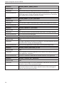
12.21 Error codes from the device
Definition
SENSOR_NO_ERRORS
Numeric value
0
Description
No errors
Solution/Workaround
–
Definition
SENSOR_NO_ACTIVE_CONFIG
Numeric value
0100
Description
No application is currently loaded in the sensor.
Solution/Workaround
Some commands need a current application. If this is not the case, an error
occurs.
Definition
SENSOR_INVALID_PARM
Numeric value
0105
Description
Invalid input parameter
Solution/Workaround
Read the command documentation to send the required information to the
sensor.
Definition
SENSOR_INVALID_STATE
Numeric value
0108
Description
The sensor is in an operation mode which does not permit the execution of
commands.
Solution/Workaround
Check the command documentation to see when the command can be executed.
Definition
SENSOR_ERR_NO_MEM
Numeric value
0110
Description
Fatal internal error.
Solution/Workaround
Reboot the sensor.
Definition
SENSOR_CONFIG_NOT_FOUND
Numeric value
0902
Description
Application to be activated not found.
Solution/Workaround
Check whether the application number is correct. Check also if the application
can be edited using the PC Software.
Definition
SENSOR_INVALID_TRIGGER_MODE
Numeric value
1000
Description
It is not possible to trigger the sensor because the trigger function via TCP/IP;
EtherNet/IP is not activated.
Solution/Workaround
Review the sensor configuration to change the sensor trigger mode.
UK
35
Object recognition sensor O2D22x
Definition
SENSOR_OBJECT_IMAGE_INVALID
Numeric value
1300
Description
Internal fault during the image transmission from/to the sensor.
Solution/Workaround
Check which is the required image format and if all parameters for the results via
TCP/IP are correct. In case of a problem during the transmission of information,
check whether the information to be sent is correct.
Definition
SENSOR_RESULT_ID_NOT_AVAILABLE
Numeric value
1600
Description
The user tries to obtain a result although no results are available in the sensor.
Solution/Workaround
–
Definition
SENSOR_CURRENTLY_DECODING
Numeric value
1601
Description
The command cannot be executed because the sensor is currently decoding.
Solution/Workaround
Try to execute the command again.
Definition
SENSOR_IMAGE_FORMAT_MISSMATCH
Numeric value
1602
Description
An image is uploaded to the sensor for evaluation. The format detected does not
match that of the currently activated application.
Solution/Workaround
Edit the running application to check which is the required image format.
Definition
SENSOR_CONFIG_SWITCHING_ACTIVE
Numeric value
1603
Description
It is not possible to upload an application to the sensor if the external selection
of the application is activated.
Solution/Workaround
Use the PC Software to deactivate the external selection of the application.
Definition
SENSOR_TRIGGER_NOT_AVAILABLE
Numeric value
1604
Description
The user sends a trigger via TCP/IP; EtherNet/IP to the device. Due to an internal fault the sensor cannot process the trigger.
Solution/Workaround
This error code shows a sensor failure. Normally the sensor tries to remedy the
failure itself. If this error occurs again, reboot the sensor. When the trigger is
reduced, this fault may be prevented.
36
Object recognition sensor O2D22x
13 Maintenance, repair and disposal
►► Keep the lens window free from soiling.
Soiling may considerably affect the reading result!
►► To clean the lens window, do not use any detergents or solvents which might
damage the front glass.
►► Do not open the housing as the device does not contain any components which
can be repaired by the user. The device must only be repaired by the manufacturer.
►► Dispose of the device in accordance with the national environmental regulations.
14 Approvals/standards
The CE Declaration of Conformity is available at:
www.ifm.com → Data sheet search → e.g. O2D220 → Approvals
15 Note on the software
This unit contains (maybe modified) Open Source software, which is subject to
special licensing terms.
For copyright information and licensing terms please refer to:
www.ifm.com/int/GNU
For software subject to the GNU General Public License or the GNU Lesser
General Public License the source code can be requested against payment of the
copying and shipping costs.
The software E2D200 version 3.0 is required as of firmware version 1030.
The software is available at:
www.ifm.com → Data sheet search → e.g. O2D220 → Download/Software.
37
UK