1
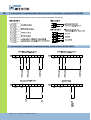
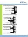
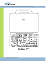
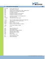
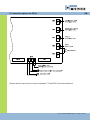
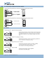
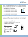
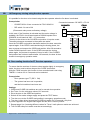
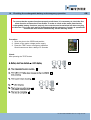
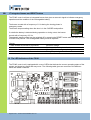
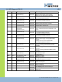
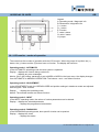
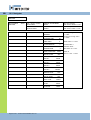
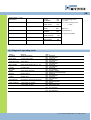
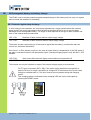
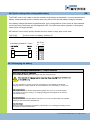
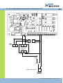
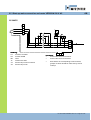
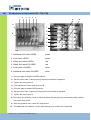
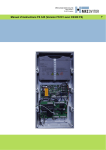
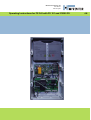
MFZ Antriebe GmbH & Co. KG
Neue Mühle 4
D-48739 Legden
Operating Instructions for FS 345 with FS 101 and CS300 FS
GB
GB
Safety advice
To enable fault-free operation to be guaranteed, it is imperative that the
rechargeable battery be replaced after every two years of operation. If this
maintenance instruction is disregarded, the functional safety of the system
and thus also the safety of buildings and persons cannot be guaranteed.
To ensure that the system always functions consistently, the fire alarm
function must be checked once every four weeks. In order to check at the
same time that the rechargeable battery also functions correctly, the controls
must be disconnected from the mains. In this way, the emergency function
can be checked to ensure that the door is closed automatically by the auxiliary
motor.
Emergency operation is not possible if there is a fault in the safety circuit of
the door operator.
To avoid a deep discharge of the rechargeable battery, the battery should not
be connected to the FS101 unit until the system is put into operation for the
first time.
If deep discharge occurs, the battery cannot be recharged again and must be
replaced immediately.
Page 2 of 36 – FS 345 FS101/CS300FS / Rev. 01
1
GB
Table of contents
1
2
3
4
5
6
7
8
9
10
11
12
13
14
15
16
17
18
19
20
21
22
23
Table of contents
Key to symbols
General safety advice
Overview of product
Start-up the emergency operation system
Start-up – gate operation system
Connection examples
Products drawing; emergency operation
Key to FS101 / DIP switch functions
Types of door operator
Connection options FS 101
Adjustment options TIMER 1
Automatic operation with active CESD in emergency mode
Emergency closing with door operator
Door sealing function
Checking the rechargeable battery and emergency operation
Integrated buzzer
Fault indicator and diagnostic LED
Display function CS 300 FS
Protective functions and charging the battery
Special interconnecting
Adjustment of limit switch
Technical data
3
3
3
5
7
7
10
12
13
14
15
17
17
18
18
19
20
20
24
28
31
34
36
2 Key to symbols
Danger of personal injury!
The safety instructions must be observed!
Warning! Danger to property!
The safety instructions must be observed!
Information
Indicates a reference to other sources of information
3 General safety advice
Guarantee
The function and safety of the equipment is only guaranteed if the warnings and safety advice in these operating
instructions are adhered to.
Use fort he intended purpose
The FS 345 controls are intended exclusively for controlling door systems with mechanical limit switches.
FS 345 FS101/CS300FS / Rev. 01 - Page 3 of 36
GB
Target group
Only qualified and trained electricians may connect, program and service the controls.
Qualified and skilled electricians must:
- have knowledge of the general and specific safety and accident prevention regulations,
- have knowledge of the relevant electrical regulations,
- be trained in the use and care of appropriate safety equipment and clothing,
- be capable of recognizing the dangers associated with electricity.
Instructions for installation and connection
- Before commencing electrical works, the system must be disconnected from the mains electricity supply and
from the emergency rechargeable battery. Measures must be taken to ensure that the electricity supply remains
disconnected for the duration of the works.
- Local safety regulations must be observed.
- Mains cables must be laid separately from control cables.
Regulations and bases for testing
For connecting, programming and servicing, the following regulations must be observed (the list is not exhaustive).
Construction product standards
- EN 12453
(Safety in use of power operated doors - Requirements)
- EN 12978
(Safety devices for power operated doors and gates - Requirements and test methods)
Electromagnetic compatibility (EMC)
- EN 50014-1
(Emission, household appliances)
- EN 61000-3-2
(Disturbances in supply systems - harmonic currents)
- EN 61000-3-3
(Disturbances in supply systems - voltage fluctuations)
- EN 61000-6-2
(Electromagnetic compatibility (EMC) - Part 6-2: Generic standards - Immunity for
industrial environments)
- EN 61000-6-3
(Electromagnetic compatibility (EMC) - Part 6-3: Generic standards - Emission
standard for residential, commercial and light-industrial environments)
Machinery guidelines
- EN 60204-1
- EN 12100-1
Low voltage
- EN 60335-1
- EN 60335-2-103
(Safety of machinery, electrical equipment of machines; Part 1: General requirements)
(Safety of machinery - Basic concepts, general principles for design - Part 1: Basic
terminology, methodology)
(Household and similar electrical appliances - Safety)
(Particular requirements for drives for gates, doors and windows)
Professional association regulations D
- BGR 232
(Directive for Power-driven Windows, Doors and Gates)
Page 4 of 36 – FS 345 FS101/CS300FS / Rev. 01
4
GB
Overview of product
Product description
The FS345 controls can be used in connection with fire proof door drives.
The FS345 controls consist of an CS300 door control unit, an FS101 auxiliary circuit board and a rechargeable
battery for the solenoid valves, magnetic clutch, DC-motor and for 24V engine brakes.
In the case of fire or power cuts, the emergency rechargeable battery provides the energy for the secondary motor
for closing the gate or for the engine brake for holding the gate.
The fire mode is triggered by a continuous command in the fire alarm contact or is time activated if the mains
power supply fails. In the case of fire, the door closes with the closing edge system deactivated, or, optionally, with
the closing edge activated.
Different models
The following models of the FS345 controls can be supplied:
- FS345 controls for dead man operation
- FS345 controls for automatic operation
- FS345 controls for automatic operation with the closing edge system activated in the case of fire
The following housing models are available:
- Housing with OPEN - STOP - CLOSE buttons
- Housing with ON / OFF key switch
- Housing with mains switch
- Housing with emergency OFF switch
The operating instructions describe the connection options and models of the FS345 controls.
FS 345 FS101/CS300FS / Rev. 01 - Page 5 of 36
GB
4.1
Product drawing
Page 6 of 36 – FS 345 FS101/CS300FS / Rev. 01
5
GB
Start-up - the emergency operation system FS 101
The FS101 circuit board includes a charger for the rechargeable battery and a microprocessor for
controlling the auxiliary drive or the engine brake.
The circuit board is connected to the CS300ME door control unit in the factory and if it is purchased
together with a door operator, the correct settings for that operator are also preset in the factory.
All that remains to be connected is a fire alarm, and the rechargeable battery must be connected to the
FS101 circuit board via a plug.
To prevent deep discharge of the rechargeable battery, the battery should not be
connected to the FS101 circuit board until the door is put into operation.
6
Start-up - gate operation system CS 300FS
Warning!
To ensure that the equipment functions properly, the following conditions must be assured:
- The door is installed and operational.
- The command and safety devices are installed and ready for operation.
- The control unit housing with the FS345 controls is installed.
- All motor connections are secured at the motor and the controls.
- All components to be connected to the controls must have at least one additional isolation with a
rated voltage of more than 230 V.
Information:
For the installation of the door and the command and safety devices, the relevant manufacturers’
instructions must be adhered to.
Mains connection
Danger!
To guarantee that the controls function properly, the following points must be
ensured:
- The mains voltage must correspond to the voltage stated on the type plate.
- For a permanent connection, an all-pole mains switch must be used.
FS 345 FS101/CS300FS / Rev. 01 - Page 7 of 36
6.1 Start up – the mains connection and the motor
6
5
~
V
N
T1
4
2
3
X12
6
L3
4
L2
PE
PE
PE
Connection:
Connection:
>
Connect the controls to the mains supply.
>
Connect the controls to the motor.
>
The groups of cables must be fixed together
close to their relevant terminals using a cable tie.
FS101 – CS 300FS (prewired)
FS101-P1-1
Page 8 of 36 – FS 345 FS101/CS300FS / Rev. 01
400V / 50Hz / 3 / N / PE
X1 L1
2
5
3
1
K1
Legend:
Legend:
K1:
Contactor CLOSED
K2:
Contactor OPEN
M1: Motor
T1:
Transformer
X1:
Terminal block for mains connection
X2:
Terminal block for motor
L1
N
K2
1
X2
U
M
W
B1
B2
CS 300FS
M1
GB
GB
6.2 Start up – the limit switches
Connection arrangement for limit switches
(CS 300FS terminals X11, X10 and FS 101 terminals X03, X05)
1
limit switch OPEN
limit switch CLOSE
3
additional limit switch CLOSE
4
additional limit switch OPEN
5
Thermal protection motor
6
emergency operation (opener)
7
safety limit switch CLOSE
8
safety limit switch OPEN
2
* factory provided: prewired
** factory provided: prewired if delivered with drive
The limit switches (excluding the additional limit switch) are analyzed by the FS101 circuit board and
the values are passed on to the CS300FS circuit board.
The allocation of terminal X11 (limit switch) was changed in relation to the allocation of
terminal of CS300FS. This must be considered during back fitting.
FS 345 FS101/CS300FS / Rev. 01 - Page 9 of 36
GB
7 Connection of command and safety devices for normal door operation X3 CS300FS
Command and safety devices can be connected via terminals X3 and X4.
7.1 Connection examples for command devices, terminal block X3/CS 300FS
Page 10 of 36 – FS 345 FS101/CS300FS / Rev. 01
7.2 Connection of safety devices X4/CS 300FS
GB
Terminal block X4 (8,2 kOhm safety edge device)
Terminal block X4 (for opto-electronic safety edge device)
Terminal block X4 (for pneumatic safety edge device – DW)
* only effective in down direction
FS 345 FS101/CS300FS / Rev. 01 - Page 11 of 36
GB
8
Product drawing of circuit board FS101 and rechargeable battery
Page 12 of 36 – FS 345 FS101/CS300FS / Rev. 01
9
GB
Key to FS101 circuit board
X01/ X02
X03
X04
X05
X06
X07
X08
X09
X10
+-AKKU
Power supply 230V / PE
Limit switch connections
Outputs for the auxiliary motor, brake, auxiliary relay
Activation of the CS 300FS circuit board
Fire alarm connection
Potential-free output for fault indicator
Potential-free output for fire alarm
Potential-free output for closing edge device
Input, external 24 V
Terminal block for battery pack
Time 1
Time 2
S303
Reset
Test
F200
ON
Time-controlled closing if mains power supply fails
Timing element for door seal function
DIP switches
Button – switch off buzzer
Button for testing emergency operation
3.15 A fuse for battery charger
button
K04
K05
K06
K07
K08
K09
K10
K11
K12
Relay secondary motor
Relay engine brake
Relay OPEN / CLOSE command
Relay limit switch OPEN
Relay limit switch CLOSE
Relay Stop
Relay Function / Error
Relay Emergency mode
Relay Closing edge
FS 345 FS101/CS300FS / Rev. 01 - Page 13 of 36
GB
9.1 DIP switch functions
DIP switch:
1 ON
1 OFF
2 ON
2 OFF
3 ON
3 OFF
4 ON
4 OFF
5 ON
5 OFF
6 ON
6 OFF
Door operator types FT + (HY)*
Door operator types FDF + FTA
Fire alarm as normally closed contact
Fire alarm as normally open contact
Emergency closing with 400V AC / 24 VDC
Emergency closing with 24V DC
With CESD in emergency operation
Without CESD in emergency operation
Door closes if a fault occurs
Door remains open if a fault occurs
(Door operator types HY)*
Door operator types FT
When making changes to the DIP switch settings, the following procedure must be observed:
1. Switch off the mains voltage
2. Switch off the rechargeable battery voltage
3. Change the DIP switch position as required
4. Switch on the rechargeable battery voltage
5. Switch on the mains voltage
* only with version HY
10 Types of door operator
The FS345 controls are designed for use with different types of door operator.
DIP 1 ON and DIP 6 OFF
1. FT door operators with 24V DC engine brake.
In emergency mode, the door closes under its own weight.
The weight of the door is held by the engine brake, which is still supplied with electricity.
The power supply comes from the mains adapter on the FS101 circuit board; if the mains
power is interrupted, power is supplied from the rechargeable battery.
(DIP 6 ON is needed for the version HY)
DIP 1 OFF
1. FD (FDF, FTA, FDS) door operators with 24V DC secondary motor and 24V DC
engine brake (FDF 5). In emergency mode, the door closes with the 24V DC secondary
motor.
The power supply comes from the mains adapter on the FS101 circuit board; if the mains
power is interrupted, power is supplied from the rechargeable battery.
Page 14 of 36 – FS 345 FS101/CS300FS / Rev. 01
GB
11 Connection options for FS101
* Please take the connection of the door operators FT3 and FDF6 from the attachment.
FS 345 FS101/CS300FS / Rev. 01 - Page 15 of 36
GB
11.1 Connection example for fire alarm contact
Terminal strip X06 (potential-free continuous contact as normally open contact)
Terminal strip X06 (potential-free continuous contact as normally closed contact)
ON
1
Fire alarm contact
OFF
6
5
2
4
+
24 VDC / max. 50mA
1
3
2
1
11.2 Alarms
Terminal strip X07 – relay K10 for fault indication
K10
X07/
07/FS101
FS101
2
1
Potential-free switching contact indicates the following faults:
Rechargeable battery fault / mains power failure: switches if
the battery is defective or if the battery voltage is less than
19V.
Terminal strip X08 - relay K11 for emergency closing
K11
X08/
08/FS101
FS101
2
1
Potential-free switching contact for emergency operation is
active. Switches for emergency closing.
Terminal strip X04 – relay K06 door drive command
K06
X04/
04/FS101
FS101
5
6
Potential-free switching contact for CLOSE or OPEN
command depending on DIP switches 1 and 3.
(See 12 and 13.1 for wiring and function)
Terminal strip X09 – relay K12 SKS
K12
X09/
09/FS101
FS101
2
1
Page 16 of 36 – FS 345 FS101/CS300FS / Rev. 01
Potential-free switching contact, signalize
the state from the safety edge.
GB
12 Adjustment options for TIME 1 (door closes if the mains supply fails)
With Timer 1, the controls can delay the automatic closing of the door after a mains power failure by a
set period. When set to 0, the door does not close automatically in the event of a mains failure.
If the timer is set so 0 and the mains supply is cut off for a longer period, the deep discharge protection
system of the controls comes into play. See 17.1.
0
1
2
3
4
5
6
7
8
9
-
No automatic closing in the event of mains failure
In the event of mains failure: door closes after 5 seconds.
In the event of mains failure: door closes after 15 seconds.
In the event of mains failure: door closes after 30 seconds.
In the event of mains failure: door closes after 1 minute.
In the event of mains failure: door closes after 2 minutes.
In the event of mains failure: door closes after 5 minutes.
In the event of mains failure: door closes after 15 minutes.
In the event of mains failure: door closes after 30 minutes.
In the event of mains failure: door closes after 60 minutes.
Timer 1
FS 101
13 Automatic operation with active closing edge in emergency mode
It is possible to monitoring the emergency closing procedure via an electrical contact bar. The door
continues to close if the bar is no longer activated and if a delay period of 2 seconds has elapsed. No
reversing takes place. The closing edge safety device (CESD) is checked when it reaches the upper
end position. If a fault is detected, emergency operation takes place without evaluation of the CESD.
Prerequisites:
- Connection made between CS300Fs and FS101 (see drawing)
-
Adjust relay mode 19 for relay 4 (factory setting)
-
FS101 DIP switch 4 ON (disconnect main power and battery voltage)
-
CESD has to be connect to terminal X 4
DIP 4 ON
C o n n e c tio n C S 3 0 0 F S + F S 1 0 1
CS 300FS
ACCU
+
24V D C
-
FS101
X5
7
8
K05
ON
OFF
6
5
4
3
2
1
R e la y 4
K 06 K 07 K 08 K 09
FS 345 FS101/CS300FS / Rev. 01 - Page 17 of 36
GB
14 Emergency closing using the door operator
It is possible for the door to be closed using the door operator when the fire alarm is activated.
Prerequisites:
-
CS300FS X3/9+10 are connected to FS101 X04/5+6
-
DIP switch 3 is set to ON
Connection between CS 300FS + FS101
(Disconnect main power and battery voltage)
In this case, if the fire alarm is activated and the mains voltage is
available, the FS101 circuit board sends a DOWN impulse to the
CS300FS circuit board via X06 → X3 connection.
The door is the driven to the CLOSED end position in impulse mode.
The safety elements connected to the system are active.
Once the CLOSED end position has been reached, the door cannot be
opened again. If the CESD is activated during the closing phase, the
door reverses and stops at the OPEN end position. After 30 seconds a
further DOWN impulse is sent. If the CESD interrupts the closing
phase again, the process is repeated 3 times in total. If the CLOSED
end position has not been reached after 120 seconds, the door is then
closed via emergency operation mode.
FS101
FS101
X04
CS 300 FS
X3
9
5
10
6
15 Door sealing function for FT fire door operators
To ensure that the sections of the door close together tightly in emergency
mode, the door must be driven beyond the CLOSE limit switch.
With the FS345 controls, this function is time controlled and is set using
TIMER 2. A value of 0 to 5 seconds can be selected.
Prerequisites:
- Door operator type FT (DIP 1 ON)
-
2,5
5
0
FS101
The system has been set in operation,
and the limit switches have been set.
Settings:
1. OPEN and CLOSE limit switches are set for normal door operation.
2. Set Timer 2 to the mid-range value of 2.5 seconds.
3. Drive the door to the OPEN end position.
FS 101
4. Switch off the mains voltage supply and press the TEST button.
5. The door runs to the CLOSED end position in emergency operation mode.
6. The door is then driven beyond the CLOSE limit switch for 2.5 seconds. Only then
is power supplied to the engine brake again and the door is held in position.
7. Repeat steps 2 to 6 entering different values for Timer 2 until optimum results are achieved.
8. The CLOSE safety limit switch must be set accordingly.
Page 18 of 36 – FS 345 FS101/CS300FS / Rev. 01
16
GB
Checking the rechargeable battery and emergency operation
To ensure that the system functions properly at all times, it is necessary to check the fire
alarm function at intervals of four weeks. In order to check at the same time that the
rechargeable battery functions properly, the controls must be switched off when carrying
out this test. This is the only way to demonstrate that the emergency function is operational
and that the door closes automatically via the auxiliary motor.
Procedure:
1. Drive the door to the OPEN end position.
2. Switch off the mains voltage power supply.
3. Press the TEST button: emergency operation
Should commence after a delay of 2 seconds.
FS 101
Check:
After pressing the TEST button
FS 345 FS101/CS300FS / Rev. 01 - Page 19 of 36
GB
17 Integrated buzzer and RESET button
The FS345 control unit has an integrated buzzer that gives an acoustic signal to indicate emergency
operation and the condition of the rechargeable battery.
The buzzer sounds with a frequency of 1 Hz during the closing phase in
emergency mode.
The buzzer stops sounding when the door is in the CLOSED end position.
If a defective battery is detected during operation or during a test, the buzzer
FS 101
sounds with a frequency of 3 Hz.
The acoustic warning signal can be switched off by pressing the RESET button when the door is in the
CLOSED end position. The rechargeable battery must be replaced.
Buzzer
1 note sounds at intervals of 5 seconds
1 note sounds at intervals of 1/2 second
4 short notes
1 note sounds at intervals of a second
No mains voltage
Rechargeable battery is defective
Warning before emergency closing
Emergency closing
18 The LED indicators of the FS101
The FS345 control unit is equipped with a row of LEDs that indicate the current operating status of the
system and signal any faults that may occur. The following table gives an overview of the different
faults and status conditions.
Page 20 of 36 – FS 345 FS101/CS300FS / Rev. 01
GB
18.1 LED Diagnostic FS 101
Code
Color
Description
Error diagnosis
D01
yellow
LED Safety circuit
(input X03/1,2)
LED ON
LED OFF
D02
yellow
LED Limit switch OPEN
(input X03/3,4,5)
D03
yellow
LED Limit switch CLOSE
(input X03/6,7,8)
D04
yellow
LED Auxiliary motor
(output X04/1,2)
D05
yellow
LED Engine brake
(output X04/3,4)
D06
yellow
LED Drive command
open/close
(output X04/ 5,6)
LED ON
LED OFF
LED ON
LED OFF
LED ON
LED OFF
LED ON
LED OFF
LED ON
LED OFF
D07
yellow
LED Limit switch OPEN
(output X05/1,2)
LED ON
LED OFF
D08
yellow
LED Limit switch CLOSED
(output X05/3,4)
D09
yellow
LED Stop circuit
(output X05/5,6)
LED ON
LED OFF
LED ON
LED OFF
D010
yellow
LED AS130 OPEN
(input X05/7,8)
LED ON
LED OFF
D011
yellow
LED AS130 CLOSE
(input X05/9,10)
LED ON
LED OFF
D012
yellow
LED Fire detector
(input X06/1,2)
LED ON
LED OFF
D013
yellow
LED Operation / fault
(output X07/3,4)
D014
yellow
LED Emergency operation
(output X08/1,2)
D015
yellow
LED CESD
(output X09/1,2)
D016
green
LED charge maintenance
D017
yellow
LED charge status
D018
red
LED ACCU fault
LED ON
LED OFF
LED ON
LED OFF
LED ON
LED OFF
LED ON
LED OFF
LED ON
LED OFF
LED ON
LED OFF
OK
Missing mains supply / ACCU voltage
Safety circuit of the operator interrupted
Limit switch OPEN not confirmed
Limit switch OPEN confirmed
Limit switch CLOSED not confirmed
Limit switch CLOSED confirmed
Auxiliary motor is active
Auxiliary motor 24V DC is not active
Engine brake is switched on
Engine brake is switched off
Drive command open/close at CS300FS active
Drive command open/close at CS300FS is not
active
Limit switch OPEN not confirmed
- Limit switch OPEN confirmed
- Emergency operation is active
Limit switch CLOSED not confirmed
Limit switch CLOSED confirmed
OK
Missing mains supply / rechargeable battery
voltage
-Safety circuit on drive unit interrupted
- Emergency operation is active
Door is moving towards OPEN in 400V operation
Door is not moving towards OPEN in 400V
operation
Door is moving towards CLOSED in 400V
operation
Door is not moving towards CLOSED in 400V
operation
Fire detector is closed
Fire detector is open
(observe DIP 2 )
operation / no fault
Battery fault, mains
Emergency operation is active
Emergency operation is not active
CESD is OK
CESD is interrupted
ACCU is charged, maintenance phase
ACCU is charging
Charging period
Not charging period, ACCU is charged
ACCU defective, CHANGE ACCU !
ACCU OK
FS 345 FS101/CS300FS / Rev. 01 - Page 21 of 36
GB
18.2 Diagnostic LED D019 F101
Code D 019, color red
Diagnostic LED
(red)
1 flash
Fault
Action
Battery fault
2 flashes
Mains power failure
Rechargeable battery is
defective: replace
Battery charger defective;
FS101 fuse F2 defective
3 flashes
Command received from fire alarm or from
T1,
the door should close
Door has been closed by the fire alarm or
by T1
Safety circuit input X03/1+2 has been
interrupted
HY Leak (only version FS345 HY))
CESD defective at OPEN end position
Door has been closed due to a fault
4 flashes
5 flashes
6 flashes
7 flashes
8 flashes
Check the safety circuit of the
door operator
Check the hydraulic system
18.3 Error diagnosis CS 300FS
Code
H4
Color
Description
green
LED
connecting block
LED ON
LED
OFF
Fault / error message
System does not respond
Cause
- No voltage supply
Door travels to the CLOSE
end position when the OPEN
button is pressed.
ERROR END POSITION
- Rotating field is connected
wrongly
ERROR RUN TIME
ERROR CESD
ERROR PRESSURE
SENSOR TESTING
- The limit switches OPEN
and CLOSE are both open,
but once have to be closed
- The programmed running
time has been exceeded
- The safety edge protection
is faulty
- Safety edge protection was
triggered
- The PS switch is not
activated at the CLOSE end
position
Page 22 of 36 – FS 345 FS101/CS300FS / Rev. 01
Error diagnosis
OK
- connecting block is interrupted
- connecting block is defective
Rectification
- Check the voltage supply of the
drive and the controls
- Check the rotating field and
establish clockwise rotating field if
necessary
- check terminal X11 connection
- check limit switch connection
- check limit switch adjustment
- check the path of the door
- Re-program the running time
- check the safety edge protection
and the spiral cable
- Remove obstruction from path
of door
- check the PS switch, spiral
cable and profile
- check the setting for the CLOSE
end position
GB
19 DISPLAY CS 300FS
Legend:
A: Operating mode / diagnostic info
B: Parameters / diagnostic info
C: + button
D: – button
E: P button
F: value / status
G: value / status
H: jumper
19.1 LCD monitor - modes of operation
The control has four modes of operation with the LCD monitor. When the jumper H is pulled, the (+)
button, the (-) button and the (P) button have no function. The display still functions.
Operating mode 1: AUTOMATIC
In the AUTOMATIC operating mode the door system is operated.
Display: - displays the function being carried out
- displays any error massages
Advice: If the „self locking“ parameter is set to MOD2 or MOD3 in the input menu, the display changes
from AUTOMATIC to MANUAL OPERATION. The buttons + and – are without function.
Operating mode 2: ADJUSTMENT
In the ADJUSTMENT mode, the OPEN/CLOSED end position settings in dead man mode are adjusted
with using the + and - buttons.
Display:
- displays the operating mode
Advise: The external buttons are without function.
Operating mode 3: INPUT
In the INPUT operating mode, the values of various parameters can be altered.
Display: - displays the selected parameter
- displays the programmed value/status
Operating mode 4: DIAGNOSIS
In the DIAGNOSIS operating mode, door-specific checks can be queried.
Display: - displays the check
- displays the status
FS 345 FS101/CS300FS / Rev. 01 - Page 23 of 36
GB
19.2. Navigator
AUTOMATIC
RESTING
uU
Push P-button > 1 sec.
ADJUSTMENT
RESTING
XXXX
Push + button: Position
DOOR OPEN
MANUAL ADJUSTMENT
OPEN
Save door position:
Push P and + button > 1 sec
Push - button: Position
DOOR CLOSED
MANUAL ADJUSTMENT
DOWN
Save door position:
Push P and - button > 1 sec
Push + and – > 2 sec.
INPUT
GERMAN
Scroll up through menu:
+ > 2 Sec
Scroll down through menu:
- > 2 Sec.
Push P-button > 1 sec.
INPUT
INPUT
RUNNING TIME
60
INPUT
TIME OPEN
0
INPUT
FOREWARNING
0
INPUT
AROUND TIME
,3
INPUT
MOD1-3 RESTING MOD1
INPUT
QUICK CLOSE
OFF
INPUT
RELAY 1
MOD6
INPUT
RELAY 2
MOD7
INPUT
RELAY 3
MOD1
INPUT
RELAY 4
MOD19
INPUT
SENSOR-TEST
OFF
INPUT
DELAY-OPEN
OFF
INPUT
SELF LOCK
MOD1
INPUT
SU-WI
MOD1
INPUT
REVERSE
MOD1
Page 24 of 36 – FS 345 FS101/CS300FS / Rev. 01
Select value: P > 1 Sec.
Increase value: +
Decrease value: Save value: P > 1 Sec.
Return to
INPUT: + and - > 1 Sec.
GB
Push P-button > 1 sec.
DIAGNOSIS
.
ES UP
ES DOWN
OPEN BUTTON
PART OPEN
CLOSE BUTTON
CESD
IMPULS
STIMER
P/E BARRIER
STOP CIRCUIT
BES-OPEN
BES-CLOSE
CYCLE
ON
ON
OFF
OFF
OFF
OFF
OFF
OFF
ON
ON
ON
ON
xxxx
Scroll up through menu:
+ > 2 Sec
Scroll down through menu:
-
> 2 Sec.
Return to
AUTOMATIC: P
Only inquiry possible
Push P-button > 1 sec.
19.3 Diagnostic operating mode
Display
ES-OPEN
Meaning
OPEN end position
ES-CLOSE
CLOSE end position
OPEN BUTTON
OPEN button
PART OPEN
PART-OPEN button (X4 / 9 + 10)
CLOSE
BUTTON
CESD
CLOSE button
Safety edge protection
IMPULS
Impulse button
TIMER
Weekly timer
P/E BARRIER
Photoelectric drive-through barrier
STOP CIRCUIT
BES-OPEN
- Stop button of controls
- Stop button of drive
Additional limit switch OPEN
BES-CLOSE
Additional limit switch CLOSE
CYCLE
Door cycle counter
Status
OFF: confirmed
ON: not confirmed
OFF: confirmed
ON: not confirmed
OFF: confirmed
ON: not confirmed
OFF: confirmed
ON: not confirmed
OFF: confirmed
ON: not confirmed
ON: System is closed
OFF: System is interrupted (fault)
OFF: confirmed
ON: not confirmed
OFF: confirmed
ON: not confirmed
ON: closed
OFF: interrupted (fault)
ON: closed
OFF: interrupted (fault)
OFF: confirmed
ON: not confirmed
OFF: confirmed
ON: not confirmed
Displays the door cycles
FS 345 FS101/CS300FS / Rev. 01 - Page 25 of 36
GB
19.4 Automatic operating mode
Display
AUTOMATIC
OPEN
AUTOMATIC
CLOSE
AUTOMATIC
RESTING
AUTOMATIC
RESTING
AUTOMATIC
RESTING
AUTOMATIC
RESTING
AUTOMATIC
RESTING
Description
The door is driven to the OPEN end position
The door is driven to the CLOSED end position
The door stands between the end position
O
The door stands at the OPEN end position
o
The door stands at the position PART OPEN („before-end position“ up)
U
The door stands at the CLOSED position
u
The door stands at the position PART CLOSED („before-end position“
down)
19.5 Input operating mode
Function
DEUTSCH
Description
Select the menu language
RUNNING TIME
Monitoring the max. running tine for an open and
close movement
After the door has opened, it runs in the CLOSE
direction again after the set time has elapsed.
Open time > 0 = impulse functions only work in
OPEN direction
The traffic light flashes before the door starts to
move downwards. The programmed forewarning
time is only active if the open time > 0 or if in
radio-impulse operating mode
Standing time at every change of direction
OPEN TIME
ADVANCE
WARNING TIME
TURNAROUND
TIME
MOD1-3
RESTING
QUICK CLOSE
RELAY 1
MOD1: in non-operative state OFF
MOD2: in non-operative state ON
ON: The open time is cut short after the
photoelectric barrier has been passed (door
closes immediately)
OFF: The open time continues as usual
First 3 Relays can be allocated to a relay mode of
1-18
MOD1: Red lights while the gate moves and
flashing in prewarning mode
MOD2: Red lights are flashing while the gate
moves and flashing in prewarning mode
MOD3: Red lights while the gate moves and in
prewarning
The parameter M1-3 non-operative state takes
effect at these 3 MOD
Page 26 of 36 – FS 345 FS101/CS300FS / Rev. 01
Setting options
DEUTSCH, ENGLISH,
FRANCAIS, ESPANOL,
NEDERLANDS, POLSKI,
CESKY
1 – 250 Seconds
Factory setting
DEUTSCH
0 – 600 Seconds
0 = auto drive OFF
0 - 120 Seconds
0 = OFF
0,1 - 2,0 Seconds
(in 1/10 Seconds)
MOD1
MOD2
ON
OFF
0,3 Seconds
MOD1 – MOD18
MOD6
60 Seconds
MOD1
OFF
GB
Function
RELAY 2
RELAY 3
RELAY 4
PRESSURE
SENSOR TEST
DELAY-OPEN
SELF LOCK
SU/WI
REVERSE
Description
MOD4: Impulse at OPEN order
MOD5: Error message
MOD6: OPEN end position
MOD7: CLOSE end position
MOD8: Final position OPEN denied
MOD9: Final position CLOSED denied
MOD10: Before-end position OPEN
MOD11: Before-end position CLOSE
MOD12: From before CLOSE position to CLOSE
position
MOD13: Magnetic locking function
MOD14: Brake
MOD15: Brake negated
MOD16: Brake remains ON during open time
MOD17: Brake remains ON in open time and
while changing direction (in SKS, brake falls
down)
MOD18: Red lights are flashing in prewarning
MOD19: SKS
ON: PS testing is active
OFF: PS testing is inactive
ON: Forewarning before opening
OFF: immediate opening
MOD1: Automatic operation
MOD2: Manual operation for OPEN and CLOSE
MOD3: Manual operation for CLOSE
MOD1: PART-OPEN button at terminal X4(9/10)
MOD2: PART-OPEN selector switch at terminal
X4 (9+10)
When the selector switch is closed, all OPEN
commands go to the before-end switch OPEN
MOD1: It does not take place a reversion, if the
additional limit switch is too operated.
MOD2: It takes place a reversion, even if the
additional limit switch is too operated.
Setting options
MOD1 – MOD18
Factory setting
MOD7
MOD1 – MOD18
MOD1
MOD 19
ONOFF
MOD19
OFF
ONOFF
OFF
MOD1 - MOD3
MOD1
MOD1MOD2
MOD1
MOD1MOD2
MOD1
FS 345 FS101/CS300FS / Rev. 01 - Page 27 of 36
GB
20 Rechargeable battery and battery charger
The FS345 control unit has protection against deep discharge of the battery and can carry out regular
tests to check the condition of the battery.
20.1 Protection against deep discharge
If, after being put into operation, the controls are operated for a longer period without the external
power supply, the control unit switches itself off after a specified length of time to prevent deep
discharge of the rechargeable battery. The length of time depends on the type of door operator and
thus on the external devices connected.
DIP 1 ON
DIP 1 OFF
Switches off after 8 hours without mains supply voltage
Switches off after 48 hours without mains supply voltage
The buzzer sounds continuously for 60 seconds to signal that the battery, and therefore also the
control unit, has been switched off.
If the timer 1 on Zero stands (no drive in the case of power failure) in dependence of the DIP switch 5
the gate is controlled closed or left alternatively open. Controlled keeping-open is only with DIP 1 OFF
possible.
DIP 5 ON
DIP 5 OFF
Gate closes after the audio signal, accumulator/control switches off
Gate remains open, for accumulator/control switches off
The controls can only be switched on again if the external voltage supply is reconnected.
For FT types of operator (DIP 1 ON), if the mains supply has been interrupted for a
period of 8 hours or longer, the battery is charged for 30 minutes as soon as the mains
voltage is switched back on. The door controls cannot operate during this charging
period.
This charging status is indicated via the recharge LED and can be interrupted by
pressing the RESET button.
FS 101
Page 28 of 36 – FS 345 FS101/CS300FS / Rev. 01
GB
20.2 Cyclic testing of the rechargeable battery
The FS345 control unit is able to test the condition of the battery automatically. In normal operation the
battery is disconnected from the controls once every 60 minutes and the battery voltage is checked.
If the battery voltage falls below a specified value, this is recognized as a fault, which is then indicated
via the fault relay, the buzzer and the diagnostic LED. It could be that proper operation in emergency
mode is then no longer possible.
DIP switch 5 can be set to specify whether the door closes or stays open in this case.
DIP 5 ON
DIP 5 OFF
The door closes, the battery switches off
The door stays open, the battery switches off
Verbindung CS300FS + FS101
DIP 5 ON
ON
CS 300FS
300FS
X3
FS101
FS101
X04
6
5
9
5
10
6
4
3
2
1
OFF
20.3 Recharging the battery
(two options)
- Disconnect your battery from the charger and store it fully charged.
- It is also possible to continue to charge your battery for an unlimited period (trickle
charging) with the charger switched on. It is advisable to store the battery in a cool room.
Charging the battery at ambient temperatures greater than 30°C is not recommended.
Your charger is set in the factory to a charging voltage that is designed for an ambient
temperature of 20°C.
Charging the battery at temperatures lower than 10°C is not recommended. The available
capacity is reduced at lower temperatures.
Please avoid deep discharge of the battery. Should this occur, recharge the battery as soon
as possible for a period of 24 hours.
FS 345 FS101/CS300FS / Rev. 01 - Page 29 of 36
GB
Page 30 of 36 – FS 345 FS101/CS300FS / Rev. 01
21.1 Connecting diagram engine brake for door operator FT3
K13
L1
N
CS 300 FS
L
GB
K14
N
Additive power
supply unit
24V DC
+
-
K14
K13
engine brake 24V DC
FS 345 FS101/CS300FS / Rev. 01 - Page 31 of 36
GB
21.2 Connecting diagram secondary motor for door operator FDF6
Page 32 of 36 – FS 345 FS101/CS300FS / Rev. 01
GB
21.3 Start-up mains connection and motor VERSION 230 V AC
6
5
~
V
2
N
T1
4
X12
6
L3
4
L2
230V / 50Hz / 3 / N / PE
X1 L1
2
5
3
1
PE
PE
PE
K1
Erklärung:
Erklärung:
K1:
contactor CLOSED
K2:
contacto OPEN
M1: motor
T1:
Transformer 230V
X1:
terminal strip mains connection
X2:
terminal strip motor
L1
N
K2
1
3
U
X2
M1
M
W
B1
B2
CS 300FS
Connection:
Connection:
>
Connect the control to the mains.
>
Connect the control to the motor.
>
Short before the corresponding screw terminals,
groukps of cables should be make safe by means
of straps.
FS 345 FS101/CS300FS / Rev. 01 - Page 33 of 36
GB
22 Adjustment of limit switch FDF / FTA / FDS
1
2
3
4
5
6
A
B
A
1
2
B
3
4
5
6
FDF
FTA / FDS
1. Additional limit switch OPEN
green
2. Limit switch OPEN
green
3. Safety limit switch OPEN
red
4. Safety limit switch CLOSED
red
5. Limit switch CLOSED
white
6. Additional limit switch CLOSED
white
1) Drive the gate to wished CLOSED position.
2) Set the control cam 5 (white) the way that the limit switch is operated.
3) Tighten the fixing screw A.
4) Fine adjustment is done with the screw B.
5) Drive the gate to wished OPEN position.
6) Set the control cam 2 (green) the way that the limit switch is operated.
7) Tighten the fixing screw A.
8) The safety limit switches 3 and 4 (red) must be set the way that they react directly after passing
the control limit switch.
9) After the operation test, control the fixing screw.
10) The additional limit switches 1 and 6 have change-over contact free of potential.
Page 34 of 36 – FS 345 FS101/CS300FS / Rev. 01
GB
Adjustment of limit switch FT
2
2. Limit switch OPEN
green
3
3. Safety limit switch OPEN
red
4
4. Safety limit switch CLOSED
red
5. Limit switch CLOSED
white
5
6
A
6. Additional limit switch CLOSED white
B
1) Drive the gate to wished CLOSED position.
2) Set the control cam 5 (white) the way that the limit switch is operated.
3) Tighten the fixing screw A.
4) Fine adjustment is done with the screw B.
5) Drive the gate to wished OPEN position.
6) Set the control cam 2 (green) the way that the limit switch is operated.
7) Tighten the fixing screw A.
8) The safety limit switches 3 and 4 (red) must be set the way that they react directly after passing
the control limit switch.
9) After the operation test, control the fixing screw.
10) The additional limit switches 1 and 6 have change-over contact free of potential.
FS 345 FS101/CS300FS / Rev. 01 - Page 35 of 36
GB
23 Technical data
Supply voltage
Power input
Motor data
Controls voltage
Batteries
Fault output relay
Emergency operation output relay
Mounting
Housing (w x h x d)
Operating temperature
Storage temperature
Protection category
Fuse provided on site
Weight
Page 36 of 36 – FS 345 FS101/CS300FS / Rev. 01
3~ 400VAC, 50 Hz, +/- 10% STANDARD
3~ 230VAC, 50 Hz, +/- 10% SPECIAL VERSION
Further voltages on request
Max. 2.2 KW
Maximum power consumption of the CS300FS controls themselves
= 250mA, secondary
Maximum power consumption of the FS101 controls themselves =
200mA, secondary
Max 2,2 KW, -3,2 A
24 VDC
Maintenance-free batteries with VdS certification
If inductive loads are connected (e.g. further relays or brakes), these
must be fitted with appropriate suppressor elements (recovery
diodes, varistors, RC circuits).
Potential-free closed circuit contact; min. 10mA; max. 230V AC / 4A.
Once contacts have been used for power circuits, they can no longer
be used for extra-low current circuits.
If inductive loads are connected (e.g. further relays or brakes), these
must be fitted with appropriate suppressor elements (recovery
diodes, varistors, RC circuits).
Potential-free closed circuit contact; min. 10mA; max. 230V AC
/16A.
Once contacts have been used for power circuits, they can no longer
be used for extra-low current circuits.
Vertical mounting on the wall, minimum height above floor = 1m
300mm x 600mm x 130 mm
+5° C … +55°C
-20°C … +85°C
IP 54
Max. 10 A K characteristic
10.5 Kg