1
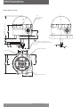
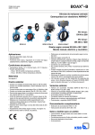
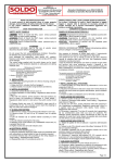
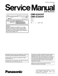
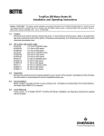
AVID CR Position Monitor
Installation & Operating Instructions
AVID
Installation and operating instructions for AVID CR
position monitors with SDPT V3 microswitches or V3
inductive proximity sensors
1.0 Mounting instructions
Note: All AVID CR switchboxes are factory equipped with Pentair direct and Namur mounting.
1.1
Please refer to the figures 1 and 2 below to determine the type of mounting that is required.
Figure 1 indicates the conventional Pentair direct mount and figure 2 details the Namur
option.
Namur shaft
drive
Pentair
11 x 16 mm
coupler
Figure 1
Actuator Namur
slot
Figure 2
1.2
Operate the actuator to the fully closed position.
1.3
Direct mount – mount the CR switchbox to the actuator by aligning the 11 x 16 mm shaft
adaptor to the actuator pinion coupler.
1.3a Secure the ModMount bracket using the 4 off supplied M5 x 16 mm socket head caps screws
(S.H.C.S) using a 4 mm A/F Allen key.
1.4
Namur mount – secure the appropriately sized Namur bracket using the screws / washers
supplied with the Namur kit. Mount the CR switchbox to the mounting bracket by engaging
the Namur shaft drive into the actuator pinion slot.
1.4a Secure the CR switchbox using the 4 off M6 x 10 mm hex head screws using an 8 mm A/F
spanner.
2.0 Cover removal
2.1
Cover
assembly
Remove the CR cover assembly by unscrewing in a counter clockwise direction. The cover
assembly consists of the inner and outer visual indicators and the indicator to shaft coupler.
Note: T
ake care when storing the CR cover assembly as this will be required when reassembling.
Any damage to the assembly may affect the ingress protection of the enclosure.
www.pentair.com/valves
Pentair reserves the right to change the contents without notice
AVDSB-0031-EN-1306
AVID CR Position Monitor
Installation & Operating Instructions
3.0 Field wiring
Attention
Before installing the conduit entry gland, please ensure that it is the correct size and thread
form. The incorrect gland will affect the enclosure ingress protection.
3.1
To remove the terminal strip slide first release the green 8-32 UNC earth screw by approx one
full turn. Then rotate the tab washer so that the small tab allows the terminal strip slide to
move vertical.
Attention
The wiring diagram for the model ordered will be on the reverse of the terminal strip slide.
Terminal strip slide,
earth screw and tab
washer
3.2 Secure the field wiring by tightening the conductors in the left hand side of the terminal strip
corresponding to the switch / sensor wires.
3.3 Insert the terminal strip slide into the enclosure by simply lining up runners into the guide
slots. When fully home rotate the tab washer so that the small tab is over the terminal strip
slide runner. Secure by hand tightening the earth screw using an appropriately sized screw
driver or 1/4” A/F socket drive.
3.4 Before proceeding with the switch / sensor cam setting, ensure that the switch / sensor wires
are neatly positioned between the wire barrier and enclosure wall.
Top cam
(open)
Push down, turn &
release
4.0 EasiFix cam setting
4.1
To set the switch or sensor cam, lift the bottom cam and turn until switch / sensor is
activated and then release. The spring will push the cam back onto the splined shaft.
4.2 Operate the actuator to the opposite extreme, push down on the top cam and turn until the
upper switch / sensor is activated.
4.3 Operate the actuator from one extreme to the other several times to ensure that the switches
/ sensors activate correctly.
Bottom cam (closed)
Lift, turn & release
5.0 Cover assembly
5.1
To aid the assembly of the cover orientate the cover assembly coupler so that the flats are in
line with the long vertical groove in the inner indicator.
5.2 Align the vertical groove of the inner indicator with the vertical rib in the housing positioned
behind the terminal strip.
5.3 Rotate the cover in a clockwise direction whilst pushing the cover assembly towards the
housing.
This action will engage the cover assembly coupler onto the shaft.
5.4 Tighten the cover to the housing to a hand tight feel.
Open
Inner indicator long
groove
Pentair reserves the right to change the contents without notice
Vertical rib in
housing
Closed
page 2
AVID CR Position Monitor
Installation & Operating Instructions
6.0 Ready for use
6.1
The CR switchbox is now ready for use.
6.2 If there are any un-used conduit entries, please ensure that they are plugged using correctly
rated IP blanking plugs.
7.0 Technical data
Area classification - non hazardous
Ingress protection - IP66
Switch / sensor options
Mechanical switch - SPDT form C,
Electrical rating -24, 48, 110 & 240 VAC / 15 Amps,
24 VDC / 15 Amps
48 VDC / 2.5 Amps
Alternative inductive proximity sensors;
P&F - NJ2-V3-N, NBB3-V3-Z4, NBB2-V3-E2
IFM - IS5026, IS5001, IS0003, IS5003, NS5002
Turck - Bi2-Q10S-AP6X, Bi2-Q10S-YOX
Telemecanique - XS7-H10PA340
Terminal strip – Weco 302 HDS, 6 or 8 points
Conduit options – up to 2 x M20 x 1.5p or 1/2”-14 NPT
Ambient temperature range – minus 20°C to +80°C
Note: For CR switchbox wiring diagrams, please visit www.pentair.com/valves
Item # Qty
Description
1
2
3
4
5
6
7
8
9
Cover assembly with HiVue indicator
Shaft assembly with NBR ‘O’rings
Terminal strip & switch assembly
Switch to shaft support plate
Housing with EPDM ‘O’ring
Actuator mounting screws
Namur & 11 x 16 mm shaft coupler
ModMount bracket
Bracket to housing screws
1
1
1
1
1
4
4
1
4
Note: Pentair do not offer replacement assemblies for the CR switchbox.
Pentair reserves the right to change the contents without notice
page 3
AVID CR Position Monitor
Installation & Operating Instructions
Overall dimensions (mm)
108.8 ref
(145 req’d for cover removal)
R44
Spherical
Up to
2x conduit entry
M20 x 1.5P or
1/2” NPT
4 holes Ø5.54 thro’, counterbored on top
Ø9.5 x 5.30 deep (to suit M5 x 16LG socket cap
head screw)
Standard conduit entry
R6.35 Type
Optional conduit entry
Pentair reserves the right to change the contents without notice
page 4