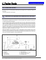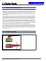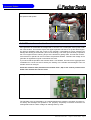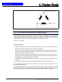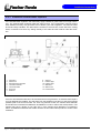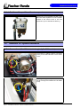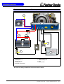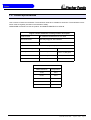
1
Installation manual
Installation, maintenance and troubleshooting
Marine Generator
Panda AGT-DC 4000 PMS
12V - 24V / 4kW
Icemaster Fischer Panda
25
20
10
10
10
since 1977
Icemaster GmbH
since 1978
Fischer Marine
Generators
since 1988
Conclusion Fischer Icemaster GmbH
since 1988
100 % water cooled
Panda generators
since 1988
Panda Vehicle
Generators
Fischer Panda
FISCHER GENERATORS have been manufactured since 1978 and are a well-known brand for first class diesel generators with especially effective sound-insulation.
Fischer has been one of the leading manufacturers in respect of quality and know-how during this period.
FISCHER, as the worldwide manufacturer of modern marine diesel generators, developed the Sailor-Silent series for
example and produced a GFK sound-insulated capsule as early as 1979 and the basis for new generator technology.
The companies Fischer and Icemaster amalgamated under the direction of Icemaster in 1988, in order to concentrate
on the development of new products. Production was moved to Paderborn.
The amalgamation of the two qualified companies led to the development of a complete new programme within a short
space of time. The aggregates developed at that time set new technological standards worldwide.
The aggregates became more efficient and powerful than other aggregates in the same nominal performance range,
because of the improved cooling. Panda generator demonstrated its superiority in several tests by renowned institutes
and magazines during the past years. The patented VCS (voltage Control System) means it can meet all demands
including motor speed. The start-booster (ASB) means Panda generators meet the highest demands in respect of
voltage stability and starting values A Panda generator, with the same drive motor, produces 15% more effective output
than the majority of conventional generators. This superiority in efficiency also ensures a fuel saving to the same extent.
The 100% water-cooled Panda Aggregate are currently manufactured in the performance range from 2 to 100 kW in
various versions. Fast running motors are preferred for performances up to approx 30 kW (Nominal speed 3000 rpm).
The heavier slow runners are preferred for the higher range. The fast running aggregates have proved themselves
many times for many uses, that they meet the demands in quality of yachts and vehicles, and offer space and weight
saving of 50% compared to slow running generators.
In addition to the Panda series, Icemaster also supply the super compact high-tech sound-insulated battery charging
aggregate from the DC/AC Panda AGT series, which is a very interesting solution for the production of mobile power.
The new HTG-alternators ensure that a charging rate of 285 amps is achieved that was scarcely thought possible for
this compact construction. This alternator replaces a separate shipboard generators (constant 230 volts AC with up to
3500 kW from the main machine)
ICEMASTER GmbH, 33104 Paderborn, reserves all rights regarding text and graphics. Details are given to the best of our knowledge. No liability is accepted for correctness. Technical modifications for improving the product without previous notice may be undertaken without notice. Before installation, it must be ensured that the Pictures,
diagrams and related material are applicable to the aggregate supplied. Enquiries must be made in case o doubt.
ii
CALIFORNIA
Proposition 65 Warning
Diesel engine exhaust and some of its constituents
are known to the State of California to cause cancer,
birth defects, and other reproductive harm.
Attention, Important Directions regarding Operation!
1. The installation certificate must be completed when taken into use, and certified by a signature.
2. The installation certificate must be despatched within two weeks of use to ICEMASTER.
3. The official guaranty confirmation will be completed by ICEMASTER after receipt and sent to the customer.
4. A guaranty must be shown to make any claims.
Claims against the guaranty will not be accepted of the above said instructions are not, or only partially, carried out.
Manufacturer declaration in terms of the machine guideline 98/37/EG .
The generator is in such a way developed that all assembly groups correspond to the CE guidelines. If machine guideline 98/37/EG is applicable, then it is forbidden to bring the generator into operation until it has been determined
that the system into which the generator is to be installed in also corresponds to the regulations of the machine guideline 98/37/EG. This concerns among other things the exhaust system, cooling system and the electrical installation.
The evaluation of the "protection against contact" can only be accomplished in connection with the respective
system. Likewise among other things responsibility for correct electrical connections, a safe ground wire connection,
foreign body and humidity protection, protection against humidity due to excessive condensation as well as the overheating through appropriate and inappropriate use in its installed state on the respective machine lies within the
responsibility of those who undertake installation of the generator in the system.
Use the advantages of the customer registration:
•
Thus you receive to extended product informations, which are sometimes safety-relevant
•
you receive, if necessarily free Upgrades
Far advantages:
By your full information Fischer Panda technicians can give you fast assistance, since 90% of the disturbances result
from errors in the periphery.
Problems due to errors in the installation can be recognized in the apron.
Technical Support per Internet:
[email protected]
iii
Safety Instructions
The electrical Installations may only be carried out be trained and
tested personnel!
The generator may not be taken into use with the cover removed.
The rotating parts (belt-pulley, belts, etc) must be so covered and protected do that there is no danger to life and
body!
If a sound insulation covering must be produced at the place of installation, then well-placed signs must show that
the generator can only be switched on with a closed capsule.
All servicing-, maintenance or repair work may only carried out, when the motor is not running.
Electrical voltages above 48 volts ( battery chargers greater than 36 volts) are always dangerous to life). The rules of
the respective regional authority must be adhered to. Only an electrician may carry out installation of the electrical
connections for safety reasons.
General safety references for the enterprise of a AGT generator.
With all energized systems, with which the current is more than 50 Ampère, special safety precautions must be
made, in order to protect the environment of the components against fire.
It is to be ensured absolutely that at the battery a main switch in well accessible place is accommodated, so that with
danger of the main switches can be separated immediately. The main switch must be however also directly at the
battery installed. If this place is not well accessible, a power relay must be used instead of the main switch which can
be served manually, which can be served then if necessary from different places. The switches for the power relay
are to mark accordingly as main switches DC battery "with danger switch off!".
Cooling of the diode block.
The diode block is cooled with fresh water. A normal cooling of the diode block is therefore only possible, as long as
the cooling water supply of the generator functions duly. The cooling water supply of the generator must be so furnished therefore that by a wide dirt deflector it is guaranteed that from outside no dirt can be sucked in into the line
system. If this is not attainable, the supply must be secured by a flow switch or a negative pressure switch. The
generator must be switched off, if the cooling water supply is impair.
The temperature safety device on the diode block can be regarded only as additional safety device. The temperature
rise at the diodes is so fast that the diodes can be damaged during a unique interruption of the cooling water supply.
A safe protection from damage of the diodes is not possible by the temperature monitoring on the diode radiator box.
Thus this can take place only by means of an appropriate external monitoring of the cooling system.
ATTENTION!
Do not connect the minus pole of the starter battery to the ground of the boat because of galvanic reason.
Warning!
Never start the generator with the battery disconnected, the diodes will be damaged!
CAUTION!
Contact of the electrical contacts may be DANGER TO LIVE!
iv
CAUTION!
The AGT-generator is not allowed to be connected to an inverter (without batteries)!
The Inverter generates voltage peaks, which can destroy the rectifier diodes of the generator!
A battery must always be connected to the inverter as a capacity!
Recommended capacity at 12V
≥ 240Ah at 24V ≥ 120Ah
The screws at the electric rectifier may be pulled tight only with a torque wrench. Torque 4Nm.
The battery cable must be secured at the generator and at the batteries with appropriate safety devices.
The generator is also include into the CO2 - fire-extinguishing system.
v
Measures to the fire protection.
All construction units in the environment of energized parts, which carry more than 50 Amp., must be fire protectionmoderately secured.
All junction points at the energized parts must be examined regularly on heating up (infrared thermometers).
Safety Instrictions for the Handling with Batteries
These instructions must be noticed additionally to the instructions of the battery manufacturer:
•
If the batteries are working, someone should be in your near area to help you in a case of emergency.
•
Water and soap must be hold ready if battery acid corrode your skin.
•
Wear eye protection and protective clothing. During working with the batteries don´t touch the eyes.
•
If you got a acid splash on your skin or clothing grow it with much water and soap out.
•
If you got acid in your eyes rinse them immediately with clear water until no cauterization is noticeable. Visit immediate a doctor.
•
Don´t smoke in the near of the batteries. Avoid naked flames or open fires. In the area of batteries exists danger
of explosions.
•
Pay attention that no tools fall on the battery poles, if necessary cover them.
•
During the installation don´t wear a wrist watch or arm jewels, you can create under these circumstances a battery
short-circuit. Burning of the skin could be the result.
•
Protect every battery contact against unintentional touch.
•
Use only cyclical profoundly dischargeable batteries. Starter batteries are not appropriate. Lead-gel batteries are
commended. They are maintenance-free, profoundly dischargeable and not produce gas.
•
Do not charge a frozen battery.
•
Avoid a batterie short-curcuit.
•
Take care of a good ventilation of the battery to drain off developing gas.
•
The battery connection terminals must be checked of a tight contact at least before operating.
•
The battery connection cable must be carefully mounted and checked about incorrect heating at operation with
load. The vibrating devices must be regulary checked about scour points and flaw in the isolation.
vi
Table of Contents
A
Mode of Operation of the Generator ................................................................................5
A.1
Mode of Operation of Operating Surveillance .................................................................... 5
A.1.1
A.1.2
A.2
Operation of the generator with HTG generator ................................................................. 8
A.2.1
Operation of the generator with automatic start ................................................................ 8
A.4
Betrieb des Generators bei Einbau unter der Wasserlinie ................................................ 9
A.5
Control of the vent valve.......................................................................................................... 10
Operation of the generator with installation over the waterline ..................................... 10
Maintenance Instructions ................................................................................................11
B.1
General maintenance instructions .................................................................................... 11
B.1.1
B.1.2
Checks before starting ............................................................................................................ 11
Hose elements and rubber formed component in the sound cover......................................... 11
B.2
Oil circuit maintenance ....................................................................................................... 11
B.3
Execution of an oil change ................................................................................................. 12
B.4
Checking the water separator in the fuel supply ............................................................. 14
B.4.1
B.4.2
De-aerating the fuel system .................................................................................................... 14
Exchange the air filter.............................................................................................................. 16
B.5
De-aerating of the coolant circuit / freshwater ................................................................. 17
B.6
Exchange of the toothed belt for the raw water pump .................................................... 18
B.7
The raw water circuit ........................................................................................................... 19
B.7.1
B.7.2
B.7.3
Clean raw water filter............................................................................................................... 19
Causes with frequent impeller waste....................................................................................... 20
Exchange of the impeller ......................................................................................................... 20
B.8
Additional maintenance ...................................................................................................... 23
B.9
Conservation at longer operation interruption ................................................................. 25
B.9.1
B.9.2
C
Allgemeine Hinweise ................................................................................................................. 8
A.3
A.4.1
B
Regulation of the generator voltage by the VCS ....................................................................... 7
Overloading of engine during longer operation ......................................................................... 8
Measures on preparation of the winter storage ....................................................................... 25
Initiation at spring .................................................................................................................... 26
Generator Failure .............................................................................................................27
C.1
Tools and measuring instruments ..................................................................................... 27
C.2
Overloading the Generator ................................................................................................. 27
C.3
Adjusting the nominal charge current .............................................................................. 28
C.3.1
C.3.2
C.3.3
C.4
Testing Generator Stator Windings ................................................................................... 32
C.4.1
C.4.2
C.4.3
C.5
Lubrication of the spiral thread spindle.................................................................................... 28
Effects of a overload to the actuator........................................................................................ 29
Low Generator-Output Voltage ............................................................................................... 31
Testing Generator Stator Winding for "Shorts" to Ground....................................................... 32
Coil Resistance Measurements in Stator Windings ................................................................ 33
Measuring the Coil Inductive Resistance ................................................................................ 34
Starting Problems ............................................................................................................... 35
C.5.1
VCS does not work.................................................................................................................. 35
Panda PMS AGT-DC 4000 - Table of Contents - Page 1
C.5.2
C.6
Troubleshooting Table ........................................................................................................37
C.5.3
D
De-aerating the fuel system.................................................................................................... 36
Fuel Solenoid Valve................................................................................................................ 37
Installation Instructions .................................................................................................. 39
D.1
Placement .............................................................................................................................39
D.1.1
D.1.2
D.2
Generator Connections - Scheme ......................................................................................40
D.2.1
D.2.2
D.3
General References ...............................................................................................................
The electrical fuel pump .........................................................................................................
Connection of the fuel lines at the tank ..................................................................................
Position of the pre-filter with water separator .........................................................................
52
53
53
54
Connection of the 12V starter battery (only for 24V version)..................................................
Terminal block AGT 4000 12V ...............................................................................................
Terminal block AGT 4000 24V ...............................................................................................
Installation of the remote control panel...................................................................................
Remote control panel for AGT-Generators.............................................................................
The speed sensor ...................................................................................................................
54
55
55
56
56
61
Generator DC System-Installation .....................................................................................62
D.8.1
D.8.2
D.9
Installation of the standard exhaust system ........................................................................... 48
Exhaust / water separator....................................................................................................... 49
Installation exhaust/water separator ....................................................................................... 50
Generator DC System-Installation .....................................................................................54
D.7.1
D.7.2
D.7.3
D.7.4
D.7.5
D.7.6
D.8
De-aerating at the first filling of the internal cooling water circuit ........................................... 45
Pressure test for control of cooling water circuit ..................................................................... 47
Scheme for freshwater circuit at two circuit cooling system ................................................... 47
Fuel System Installation .....................................................................................................52
D.6.1
D.6.2
D.6.3
D.6.4
D.7
42
42
42
43
44
Watercooled Exhaust System ............................................................................................48
D.5.1
D.5.2
D.5.3
D.6
General References ...............................................................................................................
Installation of the thru-vessel fitting in Yachts ........................................................................
Quality of the raw water sucking in line ..................................................................................
Installation above waterline ....................................................................................................
Installation below waterline.....................................................................................................
The Freshwater - Coolant Circuit .......................................................................................45
D.4.1
D.4.2
D.4.3
D.5
Connections Panda AGT 4000 12V ....................................................................................... 40
Connections Panda AGT 4000 24V ....................................................................................... 41
Cooling System Installation - Raw water ..........................................................................42
D.3.1
D.3.2
D.3.3
D.3.4
D.3.5
D.4
Placement and Basemount .................................................................................................... 39
Notice for optimal sound insulation......................................................................................... 39
Installation Panda AGT 12V-sytem ........................................................................................ 62
Installation Panda AGT 24V-system....................................................................................... 63
Voltage Control System ......................................................................................................65
D.10 Voltage controller ................................................................................................................67
D.10.1
D.10.2
D.10.3
F
Page 2
Adjustment of the rated voltage .............................................................................................. 67
Functional decription of the voltage controller ........................................................................ 67
Time lag of the switching points ............................................................................................. 68
Tables .................................................................................................................................. I
F.1
Trouble shooting ..................................................................................................................III
F.2
Technical Data Engine ....................................................................................................... VII
Panda PMS AGT-DC 4000 - Table of Contents
F.3
Types of coil .......................................................................................................................VIII
F.4
Inspection checklist for services ........................................................................................IX
F.5
Engine oil ...............................................................................................................................X
F.6
Coolant specifications .........................................................................................................XI
F.7
Measurements .....................................................................................................................XII
Panda PMS AGT-DC 4000 - Table of Contents - Page 3
Page 4
Panda PMS AGT-DC 4000 - Table of Contents
Mode of Operation of the Generator
A. Mode of Operation of the Generator
A.1 Mode of Operation of Operating Surveillance
Internal monitoring switches
The generator is equipped about failure switches, which are indicated on the remote control
panel, and also about failure switch, which switch-off the generator automatically without indicating a failure in the remote control panel:
The remote control panel supervised the following values. In the case of a disturbance the generator is switched off, in order to avoid damage to the aggregate:
1. Cooling water temperature at engine and exhaust connection
2. Thermo-switches on the Diode block
3. Coil temperature
4. Oil pressure
The fault is transmitted, if one of these switches measures a value that exceeds the required
value (all switches are openers). The current is switched off by the main relay. (Fuel magnet
valve closes, the fuel suction pump is switched off, VCS is switched off).
The combustion engine possesses an oil pressure control switch, which switches the engine off if
the oil pressure drops under a certain value.
The additional failure switch in the generator coil, it is not indicated at the remote control panel,
interrupts directly the current supply to the main power relay. By this constellation it is guaranteed
that the generator switches off in each case when an error is present.
This measure is, if possibly, a circuit at the remote control panel failed.
Thermo-switch at engine
The thermo-switch at the engine serves
for monitoring the engine temperature.
Fig. A.1: Thermo-switch at engine
Panda PMS AGT-DC 4000 - Chapter A: Mode of Operation of the Generator
Page 5
Mode of Operation of the Generator
Thermo-switch exhaust connection
If the impeller pump should fail, the raw
water stream fed here tears off and the
exhaust connection heats up immediately
extremely fast, since the water cooling is
missing. The thermo-switch supervises a
functioning raw water cycle.
Fig. A.2: Thermo-switch at echaust connection
Thermo.switch on the (+)-connection
bar
Fig. A.3: Thermo-switch on the (+)-connection bar
Thermo-switch on the (-)-connection
bar
Fig. A.4: Thermo-switch on the (-)-connection bar
Page 6
Panda PMS AGT-DC 4000 - Chapter A: Mode of Operation of the Generator
Mode of Operation of the Generator
Coikl thermo-switch
1. Thermo-switch coil 125°C
3
2. Generator housing
1
3. Thermo-sensor NTC 981S
(for measuring)
2
Fig. A.5: Thermo-switch coil
Oil pressure switch at diesel engine
The combustion engine is equipped with
an oil pressure control switch, which switches the engine off if the oil pressure
drops under a certain value.
Fig. A.6: Oil pressure switch
A.1.1 Regulation of the generator voltage by the VCS
The output voltage of the generator is permanently measured by the VCS (approx. 20 times per
second!). As soon as by a consumer the voltage is affected, the speed regulation provides to
adapt to the changed power demand by appropriate change of the engine speed.
Not only by the excitation of the generator it is worked against to the initiating voltage drop, but
also by the raising of the number of revolutions whereby the drive potential improves.
Panda PMS AGT-DC 4000 - Chapter A: Mode of Operation of the Generator
Page 7
Mode of Operation of the Generator
A.1.2 Overloading of engine during longer operation
Please ensure that the genset is not overloaded. Overloading occurs when the electrical load
(demand) induces a load torque in the generator which is higher than that which the diesel drive
motor can provide. Overloading causes the engine to run rough, burn oil, creates excessive
exhaust (environmentally unfriendly) and even to stall. Extra caution should be practised with
multi-power units (single and 3-phase current generation) to avoid overloading the diesel drive
engine.
The generator should only be loaded at the peak
rated power for short periods only! A high peak
current is required to start many electrical
devices, especially electric motors and compressors (from a still stand state)
The height of the rated output (P) can taken from
the identification plate attached on the housing.
In order to guarantee a long life span, the continuous load should not exceed 80% of the nominal
load. By continuous output we understand the
continuous operation of the generator over many
hours. It is harmless for the engine to supply for
2-3 hours the full rated output.
The total conception of the Panda generator guarantees that the continuous load operation does
not release superelevated temperatures of the engine also with extreme conditions. It is to be
considered that the exhaust gas values in the full load operation become more unfavorable (soot
formation).
A.2 Operation of the generator with HTG generator
A.2.1 Allgemeine Hinweise
Beside the alternating current aggregates ICEMASTER supplies also the super-compact High
tech battery load aggregates from the series of PANDA AGT in sound-insulated construction,
which represent a very interesting alternative solution in a DC-AC power technology merged for
generation of current within the mobile range.
The new HTG generators with 280 A charging current offer themselves a alternative for an
onboard current generator, if a diesel set is not intended. These generators differ according to the
technology very substantially from all conventional products. The size is so compact that you can
exchange it also against a generator according to standard. This generator can ensure a 230V
alternating current supply up to 3.000W power in connection with a PANDA HD inverter also in
continuous operation.
A.3 Operation of the generator with automatic start
If the generator set were set up far away from the location of the remote control panel that the
user cannot hear surely, whether the generator starts, a automatic starting option (accessories)
should be installed. With this option the starter is disengaged automatically, if the starting speed
is exceeded.
Page 8
Panda PMS AGT-DC 4000 - Chapter A: Mode of Operation of the Generator
Mode of Operation of the Generator
A.4 Betrieb des Generators bei Einbau unter der Wasserlinie
If the generator cannot be installed clearly at least 600mm over the waterline, a vent valve must
be installed into the raw water line. At installation beside the "midship´s line" a possible heeling
must be considered!
The water hose in the sound cover is split on the heat exchanger outlet and extended in each
case in the sound cover at both ends with a connecting nipple by a hose end. Both hose ends
must led out from the sound cover to a point, which is at least for 600mm over the waterline (if
possible in the midship´s line). The valve is inserted at the highest place, at least 600mm over the
waterline.
The tube bend must be removed. Now the
two ends are extended in each case with a
hose and attached at a value of approx.
600mm over the waterline with a ventilation valve.
1)
2)
3)
4)
5)
6)
Hull inlet
Water cock
Reducer
Raw water filter
Raw water pump
Heat exchanger
7)
8)
9)
10)
11)
Fresh water pump
Exhaust manifold, water-cooled
External vent valve
Diode block, water-cooled
Cooling water tank
Panda PMS AGT-DC 4000 - Chapter A: Mode of Operation of the Generator
Page 9
Mode of Operation of the Generator
A.4.1 Control of the vent valve
If the valve is blocked, the cooling water pipe cannot be ventilated after the stop of the generator,
the water column is not interrupted and the water can penetrate into the combustion chamber of
the engine.
This lead to destruction of the engine!
A.5 Operation of the generator with installation over the waterline
Generator over the waterline:
If the generator is installed over the waterline, a stronger impeller wear is possible, the pump can
run after the start some seconds dry.
It is very important that the impeller is exchanged every few months. When starting the generator
attention should be always paid and heard to it, when raw water withdraws from the exhaust
neck. If this takes longer than 5 seconds the impeller must exchanged, he sucks in air before raw
water reaches the impeller (see picture below) and the impeller then wears strongly. In this case
the impeller loses his effect and raw water can penetrate into the engine as well as substantially
destroy it. If the impeller is not exchanged early enough, the entire pump must be replaced.
Otherwise the impeller wings breaks in pieces and it stresses some time to remove these again.
Replacement impeller should always be on board.
With the installation of the generator it must be paid attention that the impeller pump is well
accessible, since the impeller is a wearing part. If this place at the location can be reached not
well, an external pump with electric drive can be used instead of the pump built firmly in the sound
cover, which should be installed in a well accessible place.
1)
2)
3)
4)
5)
Page 10
Hull inlet
Reducer
Water cock
Raw water filter
Raw water pump
6)
7)
8)
9)
10)
Heat exchanger
Fresh water pump
Exhaust manifold, water-cooled
Diode block, water-cooled
Cooling water tank
Panda PMS AGT-DC 4000 - Chapter A: Mode of Operation of the Generator
Maintenance Instructions
B. Maintenance Instructions
B.1 General maintenance instructions
B.1.1 Checks before starting
• Oil level
• Cooling system leaks
• Visual check for any changes, leaks oil drain system, v-belt, cable connections, hose clips, air
filter, fuel lines
Once a month
• Lubrication of actuator-trapezoid thread spindle
Maintenance see Table F.4, “Inspection checklist for services,” on Page IX.
B.1.2 Hose elements and rubber formed component in the sound cover
Check all hoses and hose connections for good condition. The rubber hoses are very sensitive to
enviromental influences. They can season fast with dry air, in which environment of muted oil and
fuel steams and increased temperature. The hoses must be checked regularly for elasticity.
There are operating situations, at which the hoses must be renewed once in the year.
Additionally to usual tasks of maintenance (oil level check, oil filter control etc.) further maintenance activities are to be accomplished for marine aggregates.
B.2 Oil circuit maintenance
The first oil change is to be accomplished after a period of operation from 35 to 50 hours. Afterwards the oil is to be changed after 100 hours. For this the oil SAE30 for temperatures over 20°C
and SAE20 for temperatures between 5°C and 20°C is to be used. At temperatures under 5°C oil
of the viscosity SAE10W or 10W-30 is prescribed.
Type and amount of required oil see:Table F.5, “Engine oil,” on Page X and Table F.2, “Technical
Data Engine,” on Page VII.
Panda PMS AGT-DC 4000 - Chapter B: Maintenance Instructions
Page 11
Maintenance Instructions
B.3 Execution of an oil change
Oil drain hose
For the oil change an oil drain hose is lead
through the sound cover.
Oil drain screw
The oil can be discharged by opening the
oil drain screw. For countering use a
second wrench.
13
Oil drain pump
If discharging of the oil is not possible, we
recommend the employment of a hand
pump, which can be attached to the oil
drain hose.
Afterwards the oil drain screw is closed
again.
Page 12
Panda PMS AGT-DC 4000 - Chapter B: Maintenance Instructions
Maintenance Instructions
Oil strainer
The oil strainer must be cleaned every 500
opeatiing hours.
Open the oil filler neck
After opening the cap of the oil filler neck
the new oil is refilled.
Please wait instant, before measure the oil
level, the oil must set off in the sump.
Oil dipstick
With the help of the engine oil dipstick the
oil level is to examined. The prescribed filling level may not exceed the „Max“ marking.
We recommend 2/3 oil level.
Panda PMS AGT-DC 4000 - Chapter B: Maintenance Instructions
Page 13
Maintenance Instructions
B.4 Checking the water separator in the fuel supply
The pre-filter with water separator has a
cock at its lower surface, with this cock the
downward sunk water can be discharged.
This is simply possible, water is heavier
due to its density than the Diesel.
B.4.1 De-aerating the fuel system
Normally, the fuel system is designed to bleed out air itself i.e. as soon as the electric starter
motor starts operation the fuel pump starts working and the fuel system will be de-aerated after
some time automatically. It is nevertheless essential to bleed the system as follows prior to the
first operation (as all hoses are empty):
1.Put a container under the fuel return
pipe to catch running out fuel to catch.
Page 14
Panda PMS AGT-DC 4000 - Chapter B: Maintenance Instructions
Maintenance Instructions
2. Take off the plug at the solenoid of the
starter motor.
3. Switch the panel „ON“.
4. Press „START“-button. The fuel pump
runs audible.
5. Switch the panel „OFF“.
6. Switch the panel „ON“.
7. Press again the „START“-button.
This procedure must be repeated
several times, until fuel (nonporously)
withdraws perfectly at the fuel return
pipe.
8. Switch the panel „OFF“.
9. Attach the plug at the solenoid of the
starter motor.
Panda PMS AGT-DC 4000 - Chapter B: Maintenance Instructions
Page 15
Maintenance Instructions
B.4.2 Exchange the air filter
Open the air suctin housing by loosen the
six hexagon head screws on the frame
cover.
Change the air filter mat and close the
cover again.
Page 16
Panda PMS AGT-DC 4000 - Chapter B: Maintenance Instructions
Maintenance Instructions
B.5 De-aerating of the coolant circuit / freshwater
Special notes for the ventilation of the cooling system
If the cooling water is drained or if other air should have arrived into the cooling system, it is
necessary to de-aerate the cooling system. This de-aerate procedure must be repeated several
times:
ATTENTION ! Before opening the de-aerating points the generator must be stagnant !!!
Open the ventilation valve over the cooling water pump.
10
Fill in cooling water into the cooling water
filler neck. If it is to be recognized that the
cooling water level does not fall anymore
(with cold cooling water the cooling water
levelmust cover the sheet metal in the
exhaust elbow), close the filler-cap and
the cooling water screws and start the
generator.
Start the generator for max. 60 seconds.
Switch the generator off.
Repeat this procedure several times.
If no change of the cooling water level can be determined, the generator is started for 5 minutes.
Afterwards repeat the de-aeration two - three times.
It is meaningful to repeat the de-aeration procedure also after some days again to guarantee that
in the system remained bubbles are removed.
Panda PMS AGT-DC 4000 - Chapter B: Maintenance Instructions
Page 17
Maintenance Instructions
B.6 Exchange of the toothed belt for the raw water pump
The relative high ambient temperature in the closed sound insulated capsule (about 85°C) can be
a reason for a reduced lifespan of the toothed belts. It is possible that the "softener" in the rubber
compound lose their effect after a short operating time because the air in the sound insulated
capsule can be relative warm and dry.
The toothed belt must be controlled in a very short time interval. It can be happen to change the
toothed belt after some weeks because of unfavorably conditions. Therefore the control is needed in an interval of 100 operating hours. The v-belt ia a wearing part. It should be enough spare
toothed belts on board. We suggest to stand by the according service-packet.
Loosen the fixing bolts at the raw water
pump.
Down-pull the toothed belt and put a new
on.
Type of toothed belt: Gate power Grip GT
MR (HTD-410-6-692-M5).
Page 18
Panda PMS AGT-DC 4000 - Chapter B: Maintenance Instructions
Maintenance Instructions
Screw on the raw water pump again.
Fasten the fixing bolts to the raw water
pump again.
B.7 The raw water circuit
B.7.1 Clean raw water filter
The raw water filter should be released regularly
from arrears. In each case the water cock must
be closed before. It is mostly sufficient to beat
the filter punnet.
If water should seep through the cover of the raw
water filter, this may be sealed in no case with
adhesive or sealant. Rather must be searched
for the cause for the leakage. In the simplest
case the sealing ring between caps and filter holders must be exchanged.
Panda PMS AGT-DC 4000 - Chapter B: Maintenance Instructions
Page 19
Maintenance Instructions
B.7.2 Causes with frequent impeller waste
The impeller of the cooling water pump must be regarded as wearing part. The life span of the
impeller can be extremely different and exclusively depends on the operating conditions. The
cooling water pumps of the PANDA generators are laid out in such a way that the number of revolutions of the pump lies low compared with other aggregates. This is for the life span of the pump
a positive effect.
Unfavorably affects the life span of the impeller, if the cooling water sucking in way is relatively
long or the supply is handicapped, so that the cooling water sucking in range develops a negative
pressure. This can reduce first of all the power of the cooling water pump extremely that the
wings of the impeller are exposed to very strong loads. This can shorten the life span extremely.
Further the operation of the impeller pump loaded in waters with a high portion of suspended matters. The use of the impeller pump is particularly critical in coral waterbodies. Cases are wellknown, which a impeller pump had so strongly run after 100 hours already that the lip seal on the
wave was ground in. In these cases sharp crystal parts of the coral sand assess in the rubber
seal and affect like an abrasive the high-grade steel shank of the impeller pump.
If the generator were mounted over the water level it is particularly unfavorable for the impeller
pump. After the first start some seconds will pass by, until the impeller can suck in cooling water.
This short unlubricated operation time damages the impeller. The increased wear can lead after
short time to the loss. (see special notes: "Effects on the impeller pump, if the generator is mounted over the waterline").
B.7.3 Exchange of the impeller
Close the raw water stop cock.
Page 20
Panda PMS AGT-DC 4000
- Chapter B: Maintenance Instructions
Maintenance Instructions
Raw water pump on the front side of the
genset.
Remove the cover of the raw water pump
by loosen the wing screws from the housing.
Pull to the impeller with a multigrip pliers of
the wave.
Mark the impeller, to make sure that these
is used in the correct position at re-installation.
Panda PMS AGT-DC 4000 - Chapter B: Maintenance Instructions
Page 21
Maintenance Instructions
Check to the impeller for damage and
replace it if necessary.
Before the reinsertion into the housing the
impeller should have been lubricated with
glycerin or with a non-mineral oil based
lubricant e.g. silicone spray.
The impeller is attached to the pump wave
(if the old impeller is used, pay attention to
the before attached marking).
Fastening the cover and use a new seal.
Page 22
Panda PMS AGT-DC 4000
- Chapter B: Maintenance Instructions
Maintenance Instructions
B.8 Additional maintenance
Furthermore in addition to the standards checks according to the manual following points of the
generator have to be checked:
• automatic shut down of the generator in case off high heating temperature
This shall be done by disconnecting the thermo-switch of the heat sink. Next to the rectifier you
will find a 2-pole connector. If you disconnect this connector from the opposite socket, the generator shall shut down – or, when the generator is not running you will get a signal on the panel.
Temperatures of the rectifier and heating
• Apply a thermocouple meter to the heat sink and the copper bars and monitor the maximum
temperatures of the rectifier.
• With the help of the infrared thermometer you can check all the temperatures on the rectifier.
Check all the cable connections of the DC- wiring. The easiest is to touch them carefully with
your finger. If they are getting warm or getting hot, these connections are poor and shall be replaced.
The temperature of the heat sink shall never exceed 95°C.
The temperature of the copper bars shall never exceed 120°C
Panda PMS AGT-DC 4000 - Chapter B: Maintenance Instructions
Page 23
Maintenance Instructions
Ensure, that a fuse next to the battery is installed in the battery line for the generator output cable.
Ensure that a battery switch is installed in the battery line. Never leave the generator behind without the cover mounted over the heat sink and capsule not closed.
Sicherung
Fuse
Batterie-Trennschalter
Battery switch
Sicherung
Fuse
Remind the customer
• to run the generator only with closed capsule.
• not to run the generator unattended
• to ask for regular service
Page 24
Panda PMS AGT-DC 4000
- Chapter B: Maintenance Instructions
Maintenance Instructions
B.9 Conservation at longer operation interruption
B.9.1 Measures on preparation of the winter storage
1. Rinse raw water circuit with an anti-freeze solution, even if this contains a corrosion protection
means. The raw water inlet must be removed at the water cock. Over a hose connector the
anti-freeze protection mixture is to be sucked in from a container. The leaked cooling water
with the exhaust is to be led back into the sucking in container. The circuit must be kept
upright some minutes to guaranteed that the anti-freeze protection mixture reaches all ranges
of the cooling system.
2. The concentration of the anti-freeze mixture in the internal cooling circuit must be checked
with a suitable measuring instrument. The concentration must be furnished according to the
lowest temperatures which can be expected.
3. Clean raw water filter and check seal.
4. Check water cock for practicability. And spray with a corrosion protection oil from the inside or
lubricate with acidless grease.
5. Check all hoses and hose connectors for good condition. The rubber hoses are very sensitive
to enviromental influences. They can age fast with dry air, in environment of light oil and fuel
steams and increased temperature. The hoses must be checked regularly for elasticity. There
are operating situations, which the hoses must be renewed once in the year.
6. Check the hose connectors at all raw water valves doubly and if possible protect them with
double hose clamps.
7. Dismount the impeller of the cooling water pump and check for wear. The impeller may not
remain in the pump. It must be greased with vaseline and be kept at a dark place. It can be
reintragrated in the spring again into the pump, if it is in good condition. The impeller is a wearing part, it is recommended to renew it always in the spring, independently how many operating hours the aggregate ran.
8. Control of the vent valve at the raw water inlet. If the generator is installed below the waterline,
always a vent valve is necessary. The vent valve must be checked also during the season
regularly. In the winter storage the vent valve should always be disassembled, checked and
greased. Hardens or got parts dirty are to be replaced.
9. Check water lock: If the generator were rinsed with an anti-freeze mixture, the antifreeze mixture can leave in the water lock. If the generator were rinsed with fresh water, the water in the
water lock must be drained. Otherwise the danger exists that the collector is blown up and
destroyed by ice.
10.Check the exhaust/water separator on leakage and if the hose connectors at the lower surface
of the separation unit are in normal condition. (with extremely sulfureous fuels it is possible
that also high-grade steel tube ends are attacked.)
11.Check all construction units at the generator inside the sound cover for leakages. If there are
traces of humidity in the sound cover, the cover must be dried. Further the cause for the wetness must be surched and eliminated.
12.During the winter storage the upper section of the sound cover must be taken off, in order to
avoid condensed moisture formation, if traces of humidity remain in the sound cover inside
casing by leakages in the raw water circuit.
Panda PMS AGT-DC 4000 - Chapter B: Maintenance Instructions
Page 25
Maintenance Instructions
B.9.1 Measures on preparation of the winter storage
13.The generator housing and the housing of the engine should be sprayed with a corrosion protection oil before the winter storage. This procedure is recommended also in the season. This
procedure can avoid that arising and humidity marks on the surface of the aluminum construction units be noticed too late.
14.Disconnect the starter battery (positive and negative pole).
15.Lubricate the spindle for the number of revolutions adjustment device with a special lubricant
(Antiseize grease).
16.Use of a air dehumidifier. The best way to protect a yacht in the winter storage against
damage by humidity is, to places a air dehumidifier inside the ship and locks all hatches. The
devices have a hygrometer, which switches the device off, if the humidity is under the adjusted
value. There is no better method, in order to protect pads, cable, electronics, wood, engines
etc. optimally against any rotting by humidity.
B.9.2 Initiation at spring
• Before the first start turn the engine once with the hand, in order to eliminate necessary existing
corrosion beginnings in the bushing. If necessarily carry out normal engine inspection.
• Change engine oil and engine oil filters.
• Reintegrate the impeller of the cooling water pump and check pump for leakage.
• Charge starter battery of the generator, connect cables and check battery voltage.
• Start generator and check the basic adjustments of the generator such as voltage, speed regulation etc..
• Check all switching off devices for function by operational procedures.
Icemaster does not take over adhesion for possible damages!
Page 26
Panda PMS AGT-DC 4000 - Chapter B: Maintenance Instructions
Generator Failure
C. Generator Failure
C.1 Tools and measuring instruments
In order to be able to manage disturbances while driving, following tools and measuring
instruments should belong to the equipment on board:
•
Multimeter for voltage (AC), frequency and resistance
•
Measuring instrument for inductance
•
Measuring instrument for capacity
•
Current absorbing clamps
•
Thermometer (ideal is a infrared thermometer)
•
Pressure device (pincer) für coolant circuit
C.2 Overloading the Generator
Please ensure that the genset is not overloaded. Overloading occurs when the electrical load
(demand) induces a load torque in the generator which is higher than that which the diesel drive
motor can provide. Overloading causes the engine to run rough, burn oil, creates excessive
exhaust (environmentally unfriendly) and even to stall. Extra caution should be practised with
multi-power units (single and 3-phase current generation) to avoid overloading the diesel drive
engine.
The generator should only be loaded at the peak rated power for short periods only! A high peak
current is required to start many electrical devices, especially electric motors and compressors
(from a still stand state).
In order to prolong the genset´s life expectancy, the nominal electrical demand on the system
should not be more than 70% of the rated genset peak load.
Keep PEAK LOADING demand in mind when switching on electrical devices (esp. fridge compressors, electric motors, battery chargers, kettles, etc.) which are fed by the generator. Careful
"powering up" (gradual loading) of the electrical demand on the generator will help prolong the life
of your genset! The genset can be run for several hours at partial load (i.e. 2/3 of rated power),
however it is not advised that it is run for more than 2-3 hours at full load. The Panda is designed
so as not to overheat even under extreme conditions. Note: The exhaust gas will become sooty
during peak-load operation.
Effects of Short Circuiting and Overloading on the Generator
The generator cannot be damaged by short circuiting or overloading. Short circuiting and overloading suppress the magnetic excitation of the generator, thus, no current is generated and the
voltage will collapse. This condition is immediately offset once the short-circuit has been eliminated and/or the electrical overload removed.
Panda PMS AGT-DC 4000 - Chapter C: Generator Failure
Page 27
Generator Failure
C.3 Adjusting the nominal charge current
ATTENTION! Before working on the System read the section “Safety Instructions” on
Page iv.
These adjustments may not be changed, they are sealed. The adjustments should be changed
expires the warranty.
The adjustments of the nominal charging current is made at the actuator. By the nuts on the left
and on the right at the spindle of the actuator the adjustment is limited.
The generator must be started and loaaded with the nominal dates. The engine adjusts the speed
regulator lever after a short time in such a way that the generator supplies appropriate nominal
dates. The adjusting nuts must be fixed to this point. This delimitation serves for the protection of
the generator, so that it is not overloaded.
01. Actuator
02. Spiral thread spindle
03. Ajusting nuts for min. speed
04. Spindle nut with speed regulator lever
05. Adjusting nuts for max. speed
05
04 03
02
01
During any operation at the generator all consumers have to be switched off to avoid damages at
the equipments.
C.3.1 Lubrication of the spiral thread spindle
The spiral thread spindle must be lubricated carefully and regularly. Please only use a temperatur
independence lubricant (up to 100°C) witch is also equiped with "emergency run qualities".
Spread also lubricant to the end of the nuts.
It is possible that the spindle could clamp if the spindle is not enough lubricated. Then the generator can be switched off by over- or undervoltage.
All screws at the actuator and the spindle must be ensured "solveable" with a screw safety
grease.
Page 28
Panda PMS AGT-DC 4000 - Chapter C: Generator Failure
Generator Failure
01. Actuator
02. Spiral thread spindle
02
01
C.3.2 Effects of a overload to the actuator
If the generator is overloaded the voltage falls on account of a not adequate motor power under
the nominal value. The actuator stays at the upper keystroke and tries to rev up the diesel engine.
An internal regulation limits the current to the actuator, nevertheless a longer overload can
damage the winding of the actuator. (short of the winding). The motor gets not strictly inoperative
but it can happen that the cranking torque of the actuator is getting weak. This has the consecuence that the rev spindle can not be turned to all positions faultless. Therefore the voltage of the
generator is regulated not good or sometimes not at all.
If you notice that the spindle of the actuator doesn´t run faultless, first check if the aggregate was
overloaded for a short time and if thereby the winding of the actuator was damaged. Then the
actuator has to be changed.
Check the electrical fuse (miniature slow-to-blow fuse 1,6A) on the control printed circuit
board if the actuator will not turn at all.
Change this fuse (1,6A slow to blow)
The generator can’t be damaged by an overload because the winding is overload- and short-circuit safety. But damages are possible in the periphery. Especially connected consumers are
endangered because a lower voltage can damage them by order.
Panda PMS AGT-DC 4000 - Chapter C: Generator Failure
Page 29
Generator Failure
Possible disturbances in the area of the rev regulation "VCS"
Failure
Cause
The spindle of the actuator jams
Fuse on the printed circuit board of the
VCS control is melted.
•
not regularly lubricated.
•
surface is mechanical damaged.
•
actuator is defect.
•
defect of the VCS control (short of winding).
•
signal DC missing.
•
limiting nut jams the spindle.
•
constant overload of the generator.
Steps to check the voltage control by a disturbance:
1. Switch off all electrical consumers.
2. Disconnect the plug of the actuator.
3. Turn the actuator manually to check if the adjusting nut is jamed to the limit stop points.
4. Turn the actuator manually to check if the adjusting nut on the spindel runs faultless.
If there is no result by these steps the actuator is working mechanically correct. After this the
electrical components must be checked:
1. Connect the plug of the actuator.
2. Start the generator.
3. Turn the actuator by hand and check if the spindle turns back by the motor.
4. If the motor react on the turn by manual strongly (the motor can normally hold with the fingers)
the drive will be working faultless. If there are nevertheless faults in the voltage control there is
a fault in the control VCS.
If the actuator is not moving the following points are necessary:
1. The motor turns not strongly rather weak:
•
The actuator has shorts in the winding and must be changed. (pay attention that the generator
is not overloaded anymore.)
2. The actuator does not move but the spindle can be turned manually.
•
Disconnect the plug of the actuator. Connect provisional an external voltage source 12V-DC to
the motor. The actuator don’t turns with the external voltage source. The actuator is defect and
have to be changed.
Actuator does not turn
The actuator is defect and have to be changed.
the actuator turns und works
faultless
1. Check the fuse on the VCS printed circuit board.
2. Check if the sense voltage is wired to the VCS printed circuit
board.
3. Check if the VCS supply voltage is wired to the VCS.
4. Check if the VCS outlet signal for the actuator is wired.
Page 30
Panda PMS AGT-DC 4000 - Chapter C: Generator Failure
Generator Failure
Change the VCS printed circiut board if the points above carries no clearance.
Überprüfen der Begrenzung der Generatorspannung
The mechanical voltage limitation must be checked regularly. The following steps have to be
done:
1. Disconnect the plug of the actuator.
Lower suspension point:
2. Switch off all load.
3. Connect an electrical ammeter.
4. Start the generator.
5. Turn the actuator manually to the lower suspension point.
6. Charge current must be <10 A, at U=UNenn.
Upper suspension point:
7. Connect the load.
8. Turn the actuator by hand gradually the insertable load up to the upper susoension point.
Charge current must not lay over 140A, at U=U Nenn
9. If deviations are determined, a new adjustment is necessary.
C.3.3 Low Generator-Output Voltage
ATTENTION! Before working on the System read the section “Safety Instructions” on
Page iv.
If the produced alternating voltage is too low, switch the load off, in order to relieve the generator.
Mostly the problem already solved. If the output voltage is still too low, even if all load is switched
off, the generator runs without load, you can assume one or more condensers are defective.
Panda PMS AGT-DC 4000 - Chapter C: Generator Failure
Page 31
Generator Failure
C.4 Testing Generator Stator Windings
ATTENTION! Before working on the System read the section “Safety Instructions” on
Page iv.
C.4.1 Testing Generator Stator Winding for "Shorts" to Ground
The generator stator windings can be tested as follows:
1. Ensure that the generator is "OFF" and cannot be accidentally started. Disconnect the battery.
2. Remove the cover of the power treminal box.
3. All terminal box connections are to be removed. (See appropriate circuit diagram.)
4. Remove all cables.
5. A check of the power terminal box is made by means of a multimeter to determine whether
there is continuity between the individual windings connections.
If continuity is detected for any of the combinations, the generator must be sent to the factory for
inspection and repair. If this is not possible, the stator can be rewound by a qualified tradesperson/technician. Winding diagrams can be obtained from ICEMASTER GmbH, Germany.
This test, unfortunately, is carried out at very low voltage (9V) when a normal multimeter is used.
Therefore only positive short circuits will be displayed. There is the possibility that a short circuit
will occur in spite of a negative test result (i.e. moisture). A reliable check can only be carried by
using an essentially higher voltage (approx 500V). This type of measuring instrument is normally
only used by experts.
If in doubt an electrician must check the winding for a short circuit with an isolation meter.
Diode block at the Panda generator
Page 32
Panda PMS AGT-DC 4000 - Chapter C: Generator Failure
Generator Failure
Wiring diagram
C.4.2 Coil Resistance Measurements in Stator Windings
If the testing set determined no earthing, the coil windings of the generator must be controlled
with a resistance measuring instrument (ohm meter). To measure coil resistance a meter capable
of measuring low resistances (Milli-Ohm resolution if possible) accurately. The measured resistance values should be close to the same between the following terminals:
U1-U2, V1-V2, W1-W2
Checking windings.
•
Disconnect all connections from the power terminal box. Loose the nuts and deduct the cables.
•
Remove all winding connections from the power terminal box.
•
Switch your meter in resistance range. When you put the probes of you meter together, you
should get a reading of 0.00Ohm. When you isolate the probes, the reading will be Overflow.
Please do this tests to check your meter.
•
Measure of the resistance within the individual windings. The values should be very small. It
mainly depends on the relation between the values. Some measuring instruments operate very
inaccurately, if the measured values are very small.
•
Resistance measure between different windings. If the value is in the Giga ohm area, the coil
is correct.
If you find any anormality, when doing this test, please ask your Fischer Panda dealer.
If strong deviations are measured in the individual coil windings, there is a coil short-cut in one
coil. No voltage is induced.
The actual values between the coil windings are not determined so exactly. It depends on the fact
that the values of all three measurements are as alike as possible. Deviations among themselves
refer to a coil short-cut. In this case the generator must be newly wound by a specialist.
Panda PMS AGT-DC 4000 - Chapter C: Generator Failure
Page 33
Generator Failure
C.4.3 Measuring the Coil Inductive Resistance
Unfortunately the checking of the ohmic resistance permits still no reliable statement about the
condition of the coil. If the ohmic resistance values arise inequalities between the coils, that is a
safe indication for the fact that the coil is defective. To be exactly sure the inductive resistance of
the coil have to be measured. For this a special measuring instrument is necessary, which measures the inductance of a coil.
Inductance is measured in the same way as the ohmic resistance, i.e. the coils are compared.
The value is indicated in mH (milli Henry).
Note: These values depends strongly from the measuring method (kind of the measuring instrument).
An alternative test method to check the stator windings can be performed as follows:
1. Ensure that the connection to the circuit system is disconnected.
2. All electrical wires in the power terminal box must be disconnected.
3. Reconnect the battery connections.
4. Start the generator.
5. Measure the voltages between the following terminals and compare for symmetry:
U1-U2, V1-V2, W1-W2
Page 34
Panda PMS AGT-DC 4000 - Chapter C: Generator Failure
Generator Failure
C.5 Starting Problems
C.5.1 VCS does not work
For start problems one chief cause is that the VCS doen not work. Check:
Is the voltage sense connecttion ok?
Check polatrity!
Is the shunt connection ok? Check polatrity!
Is the main supply connection ok? Check
polatrity!
Does DP+ (VCS ON) lie on clamp 6 of the
plug with 6 pins?
Panda PMS AGT-DC 4000 - Chapter C: Generator Failure
Page 35
Generator Failure
Checking the fuse on the VCS printed circuit board.
C.5.2 De-aerating the fuel system
Normally, the fuel system is designed to bleed out air itself i.e. as soon as the electric starter
motor starts operation the fuel pump starts working and the fuel system will be de-aerated after
some time automatically. It is nevertheless essential to bleed the system as follows prior to the
first operation (as all hoses are empty):
1. Put a container under the fuel return pipe to catch running out fuel to catch.
2. Take off the plug at the solenoid of the starter motor.
3. Switch the panel „ON“.
4. Press „START“-button. The fuel pump runs audible.
5. Switch the panel „OFF“.
6. Switch the panel „ON“.
7. Press again the „START“-button.
This procedure must be repeated several times, until fuel (nonporously) withdraws perfectly at the fuel return pipe.
8. Switch the panel „OFF“.
9. Attach the plug at the solenoid of the starter motor.
Page 36
Panda PMS AGT-DC 4000 - Chapter C: Generator Failure
Generator Failure
C.5.3 Fuel Solenoid Valve
For start problems the possibility of an error exists with the solenoid for engine stop or fuel solenoid valve, which both effect affect simultaneous on the fuel system.
The fuel solenoid valve is located in front of the injection pump. It opens automatically, if the
"START"-button is pressed on the remote control panel. The solenoid valve is CLOSED when the
generator main power is switched "OFF". For this reason, it requires a few seconds before the
motor comes to a full halt.
If the generator fails to start, runs rough, does not reach the proper RPM, or does not stop properly, the first item to suspect in most cases is the fuel solenoid valve and should be inspected
first.
A check of the fuel solenoid valve by removing the plug from the fuel solenoid valve for a short
period whilst in operation (first remove the small retention screw) and replace it immediately. The
motor should "react immediately" by revving high.If the motor does not react sharply to the reconnection of the solenoid wire, it is a sign that the solenoid valve could be faulty.
Fuel solenoid valve
C.6 Troubleshooting Table
For troubleshooting see “Trouble shooting” on Page III.
Panda PMS AGT-DC 4000 - Chapter C: Generator Failure
Page 37
Generator Failure
Page 38
Panda PMS AGT-DC 4000 - Chapter C: Generator Failure
Installation Instructions
D. Installation Instructions
D.1 Placement
D.1.1 Placement and Basemount
Since Panda generators have extremely compact dimensions they can be installed in tight locations, attempts are sometimes made to install them in almost inaccessible places. Please consider
that even almost maintenance-free machinery must still remain accessible at least at the front
(drive belt, water pump) and the service-side (actuator, dipstick). Please also note that in spite of
the automatic oil-pressure sensor it is still essential that the oil level has to be checked regularly.
The generator should not be installed in the proximity of light walls, which can get into resonant
vibrations by airborne sound. If this is not possible, these surfaces should line with 1mm lead foil,
so the mass and the swinging behavior are changed.
Avoid to install the generator on a smooth surface with small mass (e.g. plywood plate). This
affects in the unfavorable case like an amplifier the airborne sound waves. An improvement
obtains by compound these surfaces by ribs. Also break-throughs should be sawed, which interrupt the surface. Disguising the surrounding walls with a heavy layer (e.g. lead) plus foam material improves the conditions additionally.
The engine draws its inlet combustion air through several holes in the capsule base. Therefore
the capsule must be fitted with sufficient clearance between the capsule underside and the base
plate (min. 12mm (½")).
The generator sucks its air from the surrounding engine room. Therefore it must be ensured that
sufficient ventilation openings are present, so that the aggregate cannot overheat.
High temperature of the intake air decline the power of the aggregate and increases the coolant
temperature. Air temperatures of more than 40°C reduce the power by 2% per temperature rise
of 5°C. In order to keep these effects as small as possible, the temperature in the engine room
should not be higher than 15°C in relation to the outside temperature.
D.1.2 Notice for optimal sound insulation
The convenient base consists of a stable framework, on which the generator is fastened by
means of shock-mounts.
Since the aggregate is "free" downward, the
combustion air can be sucked in unhindered.
In addition are void the vibrations, which would
arise with a closed soil.
Panda PMS AGT-DC 4000 - Chapter D: Installation Instructions
Page 39
Installation Instructions
D.2 Generator Connections - Scheme
The generator comes supplied with all supply lines (i.e. electric cables, fuel lines etc.) already
connected to the motor and generator. The supply lines are fed through the capsule's front base
panel and are shielded at the capsule inlets with water-proof grommets.
All electrical connections, cable types and sizes must comply to the appropriate regulations. The supplied cables are rated for ambient temperatures up to 70°C (160°F). If the
cables are required to meet higher temperature requirements, they must be run through
conduits.
D.2.1 Connections Panda AGT 4000 12V
ATTENTION! Before working on the System read the section “Safety Instructions” on
Page iv.
1
3
1.
2.
3.
4.
5.
6.
Page 40
2
4
5
6
7
8
Passage for battery cable
Passage for battery cable
Raw water inltake
Cable for remote control panel
Cable for VCS
Cable for fuel pump
Panda PMS AGT-DC 4000 - Chapter D: Installation Instructions
9
7.
8.
9.
10.
11.
12.
10
11
11
Cable for voltage sense
Cable for shunt
Connection fuel IN
Connection fuel OUT
Exhaust OUT
Connection external ventilation valvel
Installation Instructions
D.2.2 Connections Panda AGT 4000 24V
ATTENTION! Before working on the System read the section “Safety Instructions” on
Page iv.
1
3
1.
2.
3.
4.
5.
6.
2
4
5
6
7
9
8
Passage for battery cable
Passage for battery cable
Raw water inltake
Cable for remote control panel
Cable for VCS
Cable for fuel pump
7.
8.
9.
10.
11.
12.
1
1.
Connection starter battery minus cable (-)
10
11
11
Cable for voltage sense
Cable for shunt
Connection fuel IN
Connection fuel OUT
Exhaust OUT
Connection external ventilation valvel
2
2.
Connection starter battery plus cable (+)
Panda PMS AGT-DC 4000 - Chapter D: Installation Instructions
Page 41
Installation Instructions
D.3 Cooling System Installation - Raw water
D.3.1 General References
The genset should have its own raw water (coolant water) inlet and should not be connected to
any other engine systems. Ensure that the following installation instructions are complied with:
Avoid galvanic corrosion
For the avoidance of galvanic corrosion the chapter "Service instruction for marine aggregates (corrosion protection)“ is to be considered.
D.3.2 Installation of the thru-vessel fitting in Yachts
It is good practice for yachts to use a hull inlet fitting with an integrated strainer. The thru-vessel
fitting (raw water intake) is often mounted against
the sailing direction to induce more water intake
for cooling.
For Panda generators, the thru-vessel inlet
should NOT point in the sailing direction! When
sailing at higher speeds more water will be forced
into the inlet than what the pump can handle and
your generator will overflood!
D.3.3 Quality of the raw water sucking in line
In order to keep the suction resistance in the line at a minimum, the raw water intake system (i.e.
sea cock, thru-hull fitting, inlet filter, etc.) must have an inner diameter of at least 1" (25mm).
This applies also to installation components such as thru-hull fitting, sea cock, raw water filter etc.
The intake suction line should be kept as short as possible. Install the raw water inlet in close proximity to the genset.
After start-up the cooling water quantity must be measured (e.g. by catching at the
exhaust). The flow rate, as well as the necessary cross section of the cooling water pipe
take from Table 1, “Diameter of conduits,” on page I.
Page 42
Panda PMS AGT-DC 4000 - Chapter D: Installation Instructions
Installation Instructions
D.3.4 Installation above waterline
The Panda is equipped with a direct drive water intake pump mounted directly on the motor.
Since the intake pump is an impeller pump there are wearing parts which will likely require replacement after some time. Ensure that the genset is installed such that the intake pump can be
easily accessed. If this is not possible, an external intake pump could be installed in an easily
accessed location.
If the generator is installed above the waterline it is possible that the impeller wearout will be
stronger. After the start the pump runs dry some seconds.
The raw water hose should describe a loop as near as possible to the raw water inlet of the gene
ator (see picture below). With it the pump only sucks in air for a short time. The impeller will be
lubricated by the raw water and its life time will rise.
By the installation of a check valve in the raw water inlet line, which is under the waterline, this
problem can be limited a little.
It is very important to change the impeller every few month. When starting the generator you
should pay attention and listen when raw water comes out from the exhaust. If this lasts longer
than 5 seconds the impeller has to be changed, because he sucks to much air before raw water
reaches the impeller and the impeller wears out strongly. In this case the impeller looses its
function, which leads to an overheating of the engine.
If the impeller isn’t exchanged early enough, the impeller wings can break into pieces and clog
the cooling circuit. Therefore it is very important to change the impeller every few month.
NOTE:
Never change the impeller for many years, without exchanging the old pump. If the sealing ring is
defective within the pump, seawater runs into the sound cover of the aggregate. A repair is then
very expensive.
Replacement impeller and also a spare pump should always be on board. The old pump can be
sent back to ICEMASTER, where it is then economically overhauled completely.
1)
2)
3)
4)
5)
Hull inlet
Reducer
Water cock
Raw water filter
Raw water pump
6)
7)
8)
9)
10)
Heat exchanger
Fresh water pump
Exhaust manifold, water-cooled
Diode block, water-cooled
Cooling water tank
Panda PMS AGT-DC 4000 - Chapter D: Installation Instructions
Page 43
Installation Instructions
D.3.5 Installation below waterline
If the generator can not be attached at least 600mm over the
waterline, a vent valve must be installed into the seawater
line. With location beside the "midship line" a possible heeling must be considered! The water hose for the external
vent valve at the back of the sound cover splits on the pressure side of the pump and at both ends in each case extended with a connecting nipple by a hose end. Both hose ends
must be led out outside of the sound cover to one point, if
possible 600mm over the waterlinee in the midship line. The
valve is connected at the highest place with the two hose
ends. If the valve is blocked, the cooling water pipe cannot
be ventilated after the stop of the generator, the water
column is not interrupted and the water can penetrate into the combustion chamber of the engine.
This leads to the destruction of the engine!
The tube bend must be removed. Now the
two ends are extended in each case with a
hose and attached at a value of approx.
600mm over the waterline with a ventilation valve.
1)
2)
3)
4)
5)
6)
Page 44
Hull inlet
Water cock
Reducer
Raw water filter
Raw water pump
Heat exchanger
Panda PMS AGT-DC 4000 - Chapter D: Installation Instructions
7)
8)
9)
10)
11)
Fresh water pump
Exhaust manifold, water-cooled
External vent valve
Diode block, water-cooled
Cooling water tank
Installation Instructions
D.4 The Freshwater - Coolant Circuit
D.4.1 De-aerating at the first filling of the internal cooling water circuit
1. For the preparation of filling the following steps are to be undertaken:
a. Open the cooling water cap on the cooling water tank.
b. Open the ventilation valve.
2. Filling the cooling water circle
a. Fill in the prepared mixture (cooling
water with anti-freeze protection according
to the intended mixture) at the filler neck at
the cooling water tank slowly so long, until
cooling water leaks at the ventilation
valve.
b. Afterwards the cooling water cap must
be screwed on firmly. Further the ventilation valve must be closed.
Panda PMS AGT-DC 4000 - Chapter D: Installation Instructions
Page 45
Installation Instructions
Anti-freeze
In the interest of safety, the freezing point of the closed circuit coolant should be checked on a
regular basis. Be sure that the coolant/antifreeze mixture is good for at least -15°C (5°F) and if it
is possible that your genset experiences lower temperatures, for example during storage or transportation, then the entire cooling system should be drained and purged. To purge the cooling
system, compressed air at about 0.5 bar (7.5 psi) is sufficient.
d. Start the generator
After filling the generator this must be started. During this first phase of start-up, the generator
may not be loaded. Switch the generator off after max. 2 minutes of operation!
3. First de-aerating
The cooling water circuit of the generator must be de-aerated now by multiple repeating of the deaerating procedure. During the entire procedure the external cooling water expansion tank
remains opened (i.e. the cap must be removed).
After the first stopping of the the generator wait about one minute until the air in the cooling water
can be drop off and raise to the highest point (ventilation point).
Now open all three ventilation points one after another as long as cooling water exit. Then the closure screw must be closed immediately. (Turn on only lightly to treat the thread.)
Pay attention that the external cooling water expansion tank is filled with enough cooling water
during the de-aerating. (If necessary refill over and over.)
One de-aerating step will be last as a rule max. 2 minutes and following steps contained:
1. The generator runs approx. 1 minute.
2. Stop the generator.
3. Hold on one minute for drop of air.
4. The collected air is led out over the two de-aeration points.
The ahead described de-aerating process must be repeated as long as after the stopping and
drop off air none air exit out of the de-aerating ports, only cooling water.
4. Again de-aerating process in the few days after the first startup
Also after the first implementing a small amount of air can be reside in the cooling circuit. To
ensure an imaculate und actual operating of the cooling system the de-aerating process must be
repeated casual in the next few days (if necessary weaks). Small amount of air will be still exit out
of the de-aerating openings especially if the generator stood still for a long time.
ATTENTION! During the de-aerating process it must be checked again and again if the
cooling water is indeed circulating. If air bubbles established in the internal cooling water
pump, it could be, that the cooling water circuit is not circulate. Then the generator would
be warming very fast and switched off by overheating.
Page 46
Panda PMS AGT-DC 4000 - Chapter D: Installation Instructions
Installation Instructions
D.4.2 Pressure test for control of cooling water circuit
Check with the hand if a temperature difference exists whether between cooling water in-flow and
cooling water return.
Feel the cooling water in-flow line at the internal cooling water pump.
Feel the cooling water return pipe either at the outlet of the water-cooled exhaust elbow union or
at the side, where this pipe entry at the heat exchanger.
The temperature difference between in-flow and return is approx. 10 degrees.
D.4.3 Scheme for freshwater circuit at two circuit cooling system
1)
2)
3)
4)
5)
6)
Hull inlet
Water cock
Reducer
Raw water filter
Raw water pump
Heat exchanger
7)
8)
9)
10)
11)
Fresh water pump
Exhaust manifold, water-cooled
External vent valve
Diode block, water-cooled
Cooling water tank
Panda PMS AGT-DC 4000 - Chapter D: Installation Instructions
Page 47
Installation Instructions
D.5 Watercooled Exhaust System
By injecting the outlet raw water into the exhaust manifold, the exhaust gases are cooled and the
noise emissions from the exhaust system are reduced.
D.5.1 Installation of the standard exhaust system
The generator exhaust system must remain completely independent and separate from the
exhaust system of any other unit(s) on board. The exhaust hose has an inner diameter of 40mm
(1.6") (Panda 14000 and above approx. 50mm). The water lock must be installed at the lowest
point of the exhaust system. An optional noise insulated water lock can also be installed. The
exhaust hose descends from the capsule to the water lock. Then the hose rises via the "goose
neck" to the silencer (see drawing). The goose neck must be vertical and sit preferably along the
ship's keel centre line. The exhaust system must be installed so that the back pressure inside the
exhaust does not exceed 0.4 bar (6 psi) and total length does not exceed 6m (20 ft.).
Exhaust diameter see “Diameter of conduits” on Page I.
1. Generator
2. Water lock
3. Goose neck
Page 48
Panda PMS AGT-DC 4000 - Chapter D: Installation Instructions
4. Hull inlet exhaust
5. Silencer
X. Distance, as small as possible
Installation Instructions
D.5.2 Exhaust / water separator
The exhaust/water separator
In order to reduce the noise level of the generator unit to a minimum, an optional exhaust outlet
muffler mounted next to the thru-hull fitting can be installed. Additionally there is component at
ICEMASTER, which exercise both functions of a "exhaust goose neck", and the water separation.
With this "exhaust/water separator" the cooling water is derived over a separate pipe. Thereby
the exhaust noises at the exterior of the yacht are strongly decreased. Particularly the "water
plash" allocate.
The water flow on the exhaust/water separator
unit has an inner diameter (ID) of 30mm. If the
path from the water separator to the sea water
outlet is very short, the hose can be further reduced to 1" (25mm) ID.
1. Raw water outlet ø 30mm
2. Hose connection ø 30mm
3. Reducer 30/20mm (if required)
4. Hose for hull inlet
5. Hose connector
6. Sea cock
7. Hull outlet
8. Hose clamps
Panda PMS AGT-DC 4000 - Chapter D: Installation Instructions
Page 49
Installation Instructions
D.5.3 Installation exhaust/water separator
If the exhaust/water separator was sufficiently highly installed, a goose neck is no longer necessary. The exhaust/water separator fulfills the same function. If the "Supersilent" exhaust system
were installed correctly, the generator will not disturb your boat neighbour. The exhaust noise
should be nearly inaudible. The best result is reached, if the hose line, which derive the cooling
water, is relocate on a short way "falling" directly to the outlet and this outlet is under the waterline.
1.
2.
3.
4.
5.
6.
7.
Generator
Water lock
Exhaust/water separator
Hull outlet exhaust
Hull outlet water
Sea cock
Reducer
8.
9.
10.
11.
12.
13.
Silencer
Exhaust pipe
Exhaust pipe
Waterline
Water hose
Exhaust hose
If the thru-hull exhaust outlet has to be mounted far from the generator, an exhaust-water separator must definitely be installed. The sea water from the separator must then run along the shortest
possible path is the thru-hull outlet. For such long exhaust routes, the exhaust hose diameter
should also be increased from NW40mm to NW50mm in order to reduce the back-pressure. The
exhaust may have a length of over 10m (32 ft.) if the exhaust hose diameter is increased to
50mm. An additional outlet exhaust muffler close to the hull outlet will help further to reduce noise
emissions.
Page 50
Panda PMS AGT-DC 4000 - Chapter D: Installation Instructions
Installation Instructions
Example of an unfavorable installation:
- water lock not deeply enough under the hights level of the generator
- distance water lock to exhaust/water separator too largely
Panda PMS AGT-DC 4000 - Chapter D: Installation Instructions
Page 51
Installation Instructions
D.6 Fuel System Installation
D.6.1 General References
Additional fuel filters (with water seperator) must be mounted outside the capsule in easily accessible places in the fuel lines between the tank intake fuel pump and the diesel motor's fuel pump.
Generally forward and return fuel flow pipes must be mounted to the diesel tanks. Do not connect
the generator fuel supply lines with any other fuel lines of other diesel systems.
The following items need to be installed:
• Fuel supply pump (12V-DC)
• Pre-filter with water separator (not part of the delivery)
• Fine particle fuel filter
• Return fuel line to fuel tank (unpressurized)
The fuel supply pump should be mounted as close to the fuel tank as possible. The electric cable
for the fuel pump is already installed on the generator (length 5m).
1
3
2
4
5
6
8
7
1. Generator
2. Fuel stop cock
3. Fuel filter
4. Fuel return pipe
Page 52
Panda PMS AGT-DC 4000 - Chapter D: Installation Instructions
5. Condensation water suction pump
6. Fuel tank
7. Fuel supply pipe
8. Electrical fuel pump (12V-DC)
Installation Instructions
D.6.2 The electrical fuel pump
Electrical fuel pump
With the Panda generator is usually supplied an external, electrical fuel pump (12V
DC). The fuel pump must be installed
close at the fuel tank. The electrical connections are preloaded at the generator
with the lead planned.
• • Suction hight of the pump: max. 1,2m at 02, bar
• • Diameter of fuel lines: “Diameter of conduits” on Page I
D.6.3 Connection of the fuel lines at the tank
Lead the return fuel pipe connected to the day tank to the floor
The return pipe connected to the tank must be dropped to the same depth as the suction pipe, if
the generfator is mounted higher than the tank, in order to prevent fuel running back into the tank
after the motor has been switched off, which can lead to enormous problems if the generator is
switched off for a long period.
Non-return Valve in the Suction Pipe
A non-return valve must be fitted to the suction pipe, which prevents the fuel flowing back after
the generator has been switched off, if it is not possible to use the return flow pipe as a submerge
pipe be placing it in the tank. The instructions "Bleeding Air from the Fuel System" must be read
after initial operation or after it has stood still for a long period, in order to preserve the starter battery.
ATTENTION! Non-return valve for the fuel return pipe
If the fuel tank should be installed over the level of the generator (e.g. daily tank), then a
non-return valve must be installed into the fuel return pipe to guaranteed that through the
return pipe no fuel is led into the injection pump.
Panda PMS AGT-DC 4000 - Chapter D: Installation Instructions
Page 53
Installation Instructions
D.6.4 Position of the pre-filter with water separator
Additionally to the standard fine filter a prefilter with water separator must be installed
outside of the sound cover in the fuel
system line. (is not included in delivery.)
D.7 Generator DC System-Installation
D.7.1 Connection of the 12V starter battery (only for 24V version)
The positive (+) battery cable is connected
direcly to the solenoid switch of the starter
motor.
The negative (-) battery cable is connected to the engine foot below the raw water
pump.
Page 54
Panda PMS AGT-DC 4000 - Chapter D: Installation Instructions
Installation Instructions
D.7.2 Terminal block AGT 4000 12V
The Panda generators are equipped with
various DC-relays, which can be found
under the terminal strip. The various
relays have the following tasks (also see
the DC circuit diagram)
F1: Fuse 15A for DC-system
F2: Fuse 10A for AC-system
K1: Starter motor relay
K2: Pre-glow relay (glow plug)
K3: Fuel pump relay
F1
F2
K1
K2
K3
D.7.3 Terminal block AGT 4000 24V
The Panda generators are equipped with
various DC-relays, which can be found
under the terminal strip. The various
relays have the following tasks (also see
the DC circuit diagram)
F1: Fuse 15A for release relay
F2: Fuse 15A for DC-system
F3: Fuse 10A for AC-system
K1: Starter motor relay
F1 F2 F3
K1
K2
K3
K4
K2: Pre-glow relay (glow plug)
K3: Fuel pump relay
K4: Release relay
Panda PMS AGT-DC 4000 - Chapter D: Installation Instructions
Page 55
Installation Instructions
D.7.4 Installation of the remote control panel
As standard a 12 core connection-cable,
7m long, is included in the supply. Cores
are numbered from 1 to 11 and the 12th
core is coloured (yellow/green). The control cables are securely connected to the
genset. On the back of the control panel
there are terminals numbered from 1 - 12.
Connect the cores of the control-cable in
respective order.
Please ensure that the remote control
panel is installed in a protected, dry and
easily accessible place.
D.7.5 Remote control panel for AGT-Generators
1
2
3
4
5
6
7
Page 56
Panda PMS AGT-DC 4000 - Chapter D: Installation Instructions
Installation Instructions
1. Display operating hours
2. Control light - temperature
3. Control light - oil pressure
4. Control light - charge control
5. Control light - operating status
red glowing
Generator is in „Stand-by“-mode
red blinking
Generator is started manually
red blinking for more than 20 seconds
Generator did not start when activated manually
green blinking
Generator runs in manual mode
green glowing
Generator runs in automatic mode
6. Switch for Manual Start:
• Switch pressure in sleeping mode: Generator is started and the panel switches to manual mode,
i.e. automatic cut off requirements are not carried out.
• Switch pressure in manual mode: If the generator starts automatically, the generator continues
to run and the panel switches to automatic mode, i.e. when the last automatic start cuts out, the
generator stops and the panel goes into sleeping mode; If the generator is not started automatically, the generator stops and the panel goes into sleeping mode.
• Switch pressure in automatic mode: The generator continues to run and the panel switches to
manual mode.
7. Main switch:
If it is already in automatic mode when it is switches on, the generator starts and the panel switches to automatic mode; If it is not in automatic mode, the panel switches to sleeping mode; If the
generator is switched off, the generator will stop in every case.
Panda PMS AGT-DC 4000 - Chapter D: Installation Instructions
Page 57
Installation Instructions
10
11
12
8
13
14
9
8. Main terminal clamp - allocation:
1: Battery plus (+)
2: Battery minus (-)
3: Input temperature failure
4: Input charge control
5: Input oil pressure failure
6: Input generator voltage 1
7: Input generator voltage 2
8: Output pre-glow
9: Output fuel pump
10: Output starter motor
11: Output VCS-ON (voltage control for VCS)
12: Output operating voltage, maximum permissible load: 0,2A
9. Terminal clamp for battery monitor - allocation:
13: Battery minus (-)
14: Input for battery monitor
The potential-free contact of a battery monitor can be connected to these two terminals, the starting sequence occurs automatically if the contact closes.
Page 58
Panda PMS AGT-DC 4000 - Chapter D: Installation Instructions
Installation Instructions
10.Terminal clamp for external automatic start - allocation:
15: Battery minus (-)
16: Input for external start demand
The potential-free contact can be connected to these two terminal. The starting sequence occurs
automatically if the contact closes.
11.Fuse 1,6A slow to blow
12.Switch for the starter motor cut-off voltage:
Switch 1: 12V - generator
Switch 2: 24V - generator
Switch 3: 36V - generator
Switch 4: 48V - generator
Attention! Only one switch may remain switched „ON“, all others must be switched „OFF“,
otherwise the complete generator could break down! An external voltage-cut-off-switch is
neccessary for voltages exceeding 48 Volts.
13.Compensation potentiometer for (12)
Is set at the factory.
14.Soldering bridge for choice of pre-glow time
• Soldering bridge open - pre-glow time 8 sec.
• Soldering bridge closed - pre-glow time 4 sec.
Attention! The panel-circuit board voltage is dangerous if the battery voltage exceeds 60
Volts. The panel must be mounted, that the voltage carrying points can not touched. This
is also the case during testing.
1. Operating and starting the Generator will works with the Control Panel. This implementing the
Main Switch (7) is effected for. By switching 'On' the Main Switch the Generator will be at first in
operaton modus. After pressing the button 'Start' (7) the Generator (Motor) will be aglow and starting. Pay attention, the button (7) will only be hold down for a second to ignitiate the start procedure.
2. Therefore with the panel it is possible, monitoring the operation modus. Hereto are beeing placed four diodes ( LED), which are connected as a pair each other, so they have the possibility to
light up in green or red.
These are:
(3) for exhaust, cooling water temperature
(4) Control unit meter - oil pressure
(5) Control unit meter - operating status
(6) Control unit meter - charge control
If (2), (3) or (4) is been illuminated red, this lights will indicate the precise cause. Illuminate constant green the genset is in operation modus.
In the starting sequence, (2) is been illuminte green, (3,4,5) red,is there no fault all diodes becomes green or green flashing when the generator runs.
Panda PMS AGT-DC 4000 - Chapter D: Installation Instructions
Page 59
Installation Instructions
Discription of the illuminate diode (5) LED
all LED´s off
Generator is off
red LED illuminates constant
Generator is in „Stand-by“-mode
red LED blinks up to 20s
Generator is in start mode
red LED blinks more than 20s
Generator had not been started --> failure
green LED blinks
The genset had been startet on the panel with
(6), runs, and can only be stopped by this button. (Even if there is a battery monitor installed).
green LED illuminates constant
The generator had been external startet by an
extern switch. This could be the battery monitor (terminal 13 and 14 on the panel) which will
start the generator after a adjusted time of one
minute if there is the voltage drops down in a
adjustable level, to reload the batteries.
On the panel at the terminal 15 and 16 is the
allocation for extern switches like thermo-,
time-, or ambient switches.
Every switch including the battery monitor will
overdrive each other. The shut down procedure will works with the switch that had been
switched.
If there is no extern switch or battery monitor
allocated, this LED becomes not constant
flashing. (however green blinking)
If the external battery monitor is inbuilt to monitoring a battery-group, it will be advisable to switch
it with an accessory (On/Off) switch. This battery monitor ensures that he will be activ while the
voltage of the batteries is on the pre-set level. Therefore there is a time delay available the genset
will run until he reached the upper level. More information see battery monitor.
Page 60
Panda PMS AGT-DC 4000 - Chapter D: Installation Instructions
Installation Instructions
D.7.6 The speed sensor
Plug for speed sensor
Installation of the speed sensor
The speed sensor tip must have between 0.3 to 0.8mm of clearance (air gap) from the gear rim
tips. In order to achieve this clearance: the speed sensor tip should be aligned with the tip of a
gear rim and screwed in until it touches the tip of the tooth. (ATTENTION! Ensure that when
inserting the sensor, that the sensor tip is not screwed into the root of the gear rim). The
screw is subsequently turned anticlockwise by half a turn (0.3 to 0.8mm) and held by a counter
nut.
1. Speed sensor on threaded seat
4
2. Engine flywheel (with gear rim)
1
3. Generator housing
4. Counter nut
2
3
1. Speed sensor on threaded seat
2. Engine flywheel (with gear rim)
1
2
1
Panda PMS AGT-DC 4000 - Chapter D: Installation Instructions
2
Page 61
Installation Instructions
D.8 Generator DC System-Installation
ATTENTION! Before the electrical system is installed, READ the “Safety Instructions” on
Page iv of this manual FIRST! Be sure that all electrical installations (including all safety
systems) comply with all required regulations of the regional authorities. This includes
lightnening conductor, personal protection switch etc.
D.8.1 Installation Panda AGT 12V-sytem
1
7
7
8
4
2
5
3
1. Generator
2. Battery bank 12V
3. Battery monitor
4. Fuel pump
6
5. Remote control panel
6. Voltage control VCS
7. Fuse
8. Battery switch
All electrical safety installations have to be made on board.
Page 62
Panda PMS AGT-DC 4000 - Chapter D: Installation Instructions
Installation Instructions
D.8.2 Installation Panda AGT 24V-system
8
1
7
8
8
9
4
2
5
3
1. Generator
2. Battery bank 24V
3. Battery monitor
4. Fuel pump
5. Remote control panel
6
6. Voltage control VCS
7. Starter battery 12V
8. Fuse
9. Battery switch
All electrical safety installations have to be made on board.
Panda PMS AGT-DC 4000 - Chapter D: Installation Instructions
Page 63
Installation Instructions
Electrical fuses
It is absolutely essential that the electrical system installation is inspected by a qualified electrical
technician. The generator should have its own AC input electrical fuses. The fuses should be
sized such that the rated current of the generator on each of the individual phases is not exceeded by more than 25%.
Data for gensets with power output greater than 30kW on request!
The fuses must be of the slow type. A 3-way motor protection switch must be installed to protect
the electrical motor.
Required cable cross-sections
The following recommended electrical cable dimensions (cross sections) are the minimum required sizes for a safe installation. (see “Cable cross-section” on Page II)
Page 64
Panda PMS AGT-DC 4000 - Chapter D: Installation Instructions
Installation Instructions
D.9 Voltage Control System
The VCS control is used for the adjustment of the number of revolutions of the engine and thus
the voltage of the generator. It belongs to the accessories and is externally attached.
VCS 12V
01
02
03
04
05
06
08
07
01. Voltage sense (+) (12V)
02. Voltage sense (-) (12V)
03. Actuator (+)
04. Actuator (-)
05. Battery voltage supply (+)
09
06. Battery voltage supply (-)
07. Stop line (regulates the actuator back at shut-off
the device)
08. Terminal shunt measurement 0mV DC (-)
09. Terminal shunt measurement 48mV DC (+)
ATTENTION!
The cable for the measuring voltage must be attached directly at the battery, and may not
attached to the output of the electric rectifier. By the voltage drop between generator and
battery the accurate voltage can only recieved direct at the battery. A false link can lead to
damage the battery!
Panda PMS AGT-DC 4000 - Chapter D: Installation Instructions
Page 65
Installation Instructions
VCS 24V
01
02
03
04
06
05
08
07
01. Voltage sense (+) (24V)
02. Voltage sense (-) (24V)
03. Actuator (+)
04. Actuator (-)
05. Battery voltage supply (+)
09
06. Battery voltage supply (-)
07. Stop line (regulates the actuator back at shut-off
the device)
08. Terminal shunt measurement 0mV DC (-)
09. Terminal shunt measurement 48mV DC (+)
ATTENTION!
The cable for the measuring voltage must be attached directly at the battery, and may not
attached to the output of the electric rectifier. By the voltage drop between generator and
battery the accurate voltage can only recieved direct at the battery. A false link can lead to
damage the battery!
Page 66
Panda PMS AGT-DC 4000 - Chapter D: Installation Instructions
Installation Instructions
D.10 Voltage controller
With a engine-operated generator set count always on the fact that through disturbances at the
controlling of the diesel engine the control of the number of revolutions monitoring is lost. In this
case the diesel engine could wind up without limitation and produce a voltage, which becomes
substantially larger than the electrical load can process. This can destroy very expensive items of
equipment. It must be take for granted that for the protection of the electrical load a voltage controller with isolating relays is used for a solid installation. The appropriate accessory components
are available at Icemaster.
If it is about a duo combination generator, the voltage control for both output parts (single phase
AC and three-phase AC) should be planned.
At different PANDA generators a voltage control is integrated. This voltage control affects only
the diesel engine. If the rated voltage exceed approx. 15%, this voltage control is activated, as
the diesel engine is turned off. This is only possible with the delay of some seconds, load could
be damaged in the meantime. The only safe method for the protection of the electrical devices is
the installation of an external voltage controller with separation contactor.
We recommend this measure with all reproduction and point out also that the generator manufacturer is not responsible for damage, which are caused by overvoltage at external devices.
Protect your valuable devices by an external voltage controller!
Position of the external voltage controller
Reasonable the external voltage controller is mounted in such a way it works not only for the
generator but for all AC voltage supplies in the electrical system, also for shore power and inverter. In these cases usually a selector switch is intended, which can be determined, which voltage
supply is switched to the electrical system. The voltage conteroller must be installed at the exit of
the selector switch, thus in the electrical system.
D.10.1 Adjustment of the rated voltage
The voltage controller must be ordered for the appropriate rated voltage (12, 24, 32, 48, 42 V
DC). Other voltage on request.
Changing between these voltages is not possible.
D.10.2 Functional decription of the voltage controller
The voltage controller has 3 different adjustment possibilities:
upper switching point, lower switching point and time lag of the generator.
In factory setting the voltage controller is in the following attitude:
a. upper switching point (disconnection) 13.6V
b. lower switching point (insertion) 11.52V
Panda PMS AGT-DC 4000 - Chapter D: Installation Instructions
Page 67
Installation Instructions
A) upper switching point (shut-down)
B) lower switching point (starting)
C) td = time lag of the generators after reaching the upper switching point
A
B
1. Voltage sense plus (+)
2. Voltage sense minus (-)
3. Charging voltage
4. Battery lower voltage
C
5. not allocated
6. not allocated
7. Output positiv (+)
8. Output negative (-)
D.10.3 Time lag of the switching points
For the upper as well as for the lower switching point a time delay is adjusted. That is, the voltage
must have overstep or fall short of the switching point on the time lag.
Following values are adjusted:
a. upper switching point (13,6V), lag: min. 20 seconds
b. lower switching point (11,52V), lag: 40 seconds
Additional notes to the recommendation "External, electrical voltage controller"
At Diesel engines count always on the fact that a diesel engine "revs up" due to special circumstances uncontrolled. This is the case if by damage to the system engine oil arrives into the sucking in way. This is possible at many engines by the crank case exhaust. A crank damage could
cause for example that by overpressure too much oil is pressed into the crank case, so that this
oil arrives into the sucking in way. The engine cannot switch off itself any longer. Usually then a
damage to the engine is the result. It would be fatal, even if this damage to the engine were the
cause of the destruction of all switched on electrical load, because uncontrolled revving up of the
Diesel engine leads also to an extreme increase of the voltage. Only by an external voltage controller with separation contactor can be prevented such damage.
Page 68
Panda PMS AGT-DC 4000 - Chapter D: Installation Instructions
Tables
F. Tables
Tabelle 1: Diameter of conduits
Ø Cooling water pipe
Generator type
Fresh water
Raw water
[mm]
[mm]
20
20
Ø Fuel hose
Ø Exhaust hose
Supply
Return
[mm]
[mm]
8
8
[mm]
Panda PMS AGT 4000
30
Tabelle 2: Technical Data
Type
Nominal power
[kW]
Continuous
power [kW]
Nominal
voltage[VDC]
Continuous
charging
current [A]
Nominal
charging
current [A]
AGT 2500-12
2,5
2,5
12
180
180
AGT 2500-24
2,5
2,5
24
90
90
AGT 4000-12
4
3,2
12
220
280
AGT 4000-24
4
3,2
24
110
140
AGT 6000-12
5,5
4,8
12
290
360
AGT 6000-24
5,5
4,8
24
170
210
AGT10.000-24
10
8
24
290
360
AGT15.000-48
15
12
48
208
260
AGT20.000-48
20
16
48
290
360
AGT25.000-72
25
20
72
240
300
AGT30.000-96
30
24
96
208
260
AGT40.000-96
40
30
96
290
360
Panda PMS AGT-DC 4000 - Chapter F: Tables
Page I
Tables
Tabelle 3: Cable cross-section
Wiring for vehicle.
single phase, not tin-plated, PVC-isolated.
nominal wire cross-section
[mm²]
at +30°C [A]
at +50°C [A]
1
19
13,5
1,5
24
17,0
2,5
32
22,7
4
42
29,8
6
54
38,3
10
73
51,8
16
98
69,6
25
129
91,6
35
158
112
50
198
140
70
245
174
95
292
207
120
344
244
a. DIN VDE 0298, part 4.
Page II
allowed conrinuous current (reference point) a
Panda PMS AGT-DC 4000 - Chapter F: Tables
Tables
F.1 Trouble shooting
GENERATOR OUTPUT VOLTAGE TOO LOW
If the generator delivers less than 24V current ("undervoltage"), there can be various reasons for this:
Cause
Solution
Generator is overloaded.
Reduce the electrical load. (Switch off load)
Motor is not reaching the rated rpm.
Refer to "motor faults" section.
Actuator is not in maximum position.
Check actuator resp. renew.
VCS-voltage controler defective or wrong adjusted.
Check resp. renew.
GENERATOR VOLTAGE TOO HIGH (MORE THAN 24V)
The following reasons may be the cause, if the generator delivers more than 24V ("overvoltage"):
Cause
Solution
The engine is running at the wrong speed.
Check the speed of the motor with a rev or frequency
counter, set the correct speed.
VCS-voltage controler defective or wrong adjusted.
Check resp. renew.
Actuator defective.
Check resp. renew.
GENERATOR VOLTAGE FLUCTUATES
Cause
1. Fault or defect on the load side.
2. A motor fault.
Solution
1. Check if the power requirement of the load fluctuates.
2. See "Motor running irregularly".
MOTOR DOES NOT TURN OVER WHEN STARTING
Cause
Solution
Battery main switch is switched off.
Check the position of the battery main switch, if necessary switch on..
Battery voltage not sufficient.
Check that connection is firm and whether corrosion
has occurred..
Starting current fault.
The voltage of full batteries fall to a maximum of 11V.
The wiring is severed if the voltage does not drop. The
battery is discharged if the voltage drops further.
Panda PMS AGT-DC 4000 - Chapter F: Tables
Page III
Tables
MOTOR TURNS OVER BUT DOES NOT START
Cause
Solution
Stop solenoid valve not opening.
Check wire connections and circuitry to solenoid valve.
(ref. DC wiring diagram: Relay K2, Fuse)
Fuel pump does not operate.
Check fuel-filter and pump: clean if necessary.
Lack of fuel.
Check fuel supply.
Glow-plugs not working correctly.
Check glow plugs and heating time.
Too much air in fuel lines.
Test fuel system for leakage. Bleed air from fuel
system (refer to section "Air-bleeding of the Fuel
System").
Fuel filter blocked.
Replace fuel filter.
Low compression pressure.
See Kubota motor-manual.
MOTOR DOES NOT TURN OVER AT THE NORMAL SPEED DURING THE STARTING PROCESS
Cause
Solution
Starter battery voltage insufficient.
Check battery.
Damaged bearing(s) piston (seized).
Repairs need to be carried out by Kubota-Service.
(refer to Kubota motor-manual)
Cooling water in combustion chamber.
1. Turn generator "OFF" at control panel.
2. Remove the glow plug (see Kubota-manual).
3. Rotate the motor by hand carefully.
4. Check if there is water in the oil and change both oil
and filter if necessary.
5. Determine cause for excess water in the combustion
chamber. The excess water can be caused by a defective air vent in the cooling water system, which should
be checked and cleaned, or replaced if faulty.
MOTOR RUNS IRREGULARLY
Cause
Solution
Faulty centrifugal injector governor.
Have the centrifugal governor inspected by a KubotaService technician.
Too much air in fuel lines.
Bleed air from fuel system.
Page IV
Panda PMS AGT-DC 4000 - Chapter F: Tables
Tables
DROP IN THE SPEED OF THE MOTOR
Cause
Solution
Too much oil.
Drain oil.
Lack of fuel.
Check fuel supply system:
- fuel filter, renew if necessary
- check fuel pump
- check fuel lines (bleed if necessary)
Lack of intake air.
Check air intake paths.
Check and clean air filter (and intake muffler if installed).
Generator overloaded by too many load.
Reduce the electrical load (switch off load).
Generator overloaded by over-energizing.
Check that the proper capacitor type is installed and
that they are connected correctly.
Defective generator (windings, bearings, or other).
Generator must be sent to manufacturer for repair of
damaged bearings or winding.
Damaged engine.
Repair of bearing damage, etc., by Kubota-Service.
MOTOR SWITCHES ITSELF OFF
Cause
Solution
Fuel solenoid valve or throttle shut solenoid is not switching off.
Check wire connections to solenoid. Check valve
functions as in the "Inlet Fuel Solenoid Valve" or in the
trottle shut off solenoid sections. Replace if necessary.
MOTOR STOPS BY ITSELF
Cause
Solution
Lack of fuel.
Check fuel supply system.
Excess heat in cooling system (thermo switch tripped)lack of cooling water. Is indicated on the remote control
panel.
Check cooling water system flow: water pump, inlet
water filter, extra heat exchanger coolant flow.
Lack of oil (oil pressure sensor tripped).
Check oil-level and if necessary top up.
Check motor's oil-pressure and have repaired by
Kubota-Service if necessary.
Panda PMS AGT-DC 4000 - Chapter F: Tables
Page V
Tables
SOOTY, BLACK EXHAUST
Cause
Solution
Generator is overloaded.
Check electrical load and switch off unnecessary load.
Insufficient intake air.
Check intake air filter; clean if necessary.
Fuel injector nozzles faulty.
Replace injector nozzles.
Valve clearance incorrect.
Readjust valve clearance to correct value (refer to
Kubota-manual).
Poor fuel quality.
Use better quality diesel (recommended: 2-D Diesel).
Poor combustion.
Incorrect AFR (air/fuel ratio) due to motor timing adjustment. Have motor serviced by Kubota.
Low compression pressure.
See Kubota motor manual.
GENERATOR MUST BE SHUT OFF IMMEDIATELY IF:
Cause
- motor rpm suddenly rises or drops
- unusual noise comes from genset
Solution
Refer to respective section of manual and if necessary,
have repaired by Kubota-Service, or Panda representative.
- exhaust colour suddenly becomes dark
- motor overheats
- oil pressure drops, oil light suddenly flashes
TROUBLESHOOTING VCS SYSTEM
Cause
Actuator does not move.
Solution
Check voltage supply and wire connections to actuator.
Motor connected?
Check connection to VCS.
Actuator sets throttle too high or too low.
Check that the wires to the actuator are connected properly (±).
Check connection to VCS.
If the VCS electronics are faulty, the generator can still run by over-riding the system. To override the VCS, disconnect the plug and jumper the contacts.
Loosen the connecting rods motor from the injection pump regulator and turn screw to a max. voltage of 33V.
Page VI
Panda PMS AGT-DC 4000 - Chapter F: Tables
Tables
F.2 Technical Data Engine
Panda AGT-DC 4000 PMS
Type
EA 300
Govenour
VCS
Cylinder
1
Bore
75mm
Stroke
70mm
Stroke volume
309cm 3
max. Power (DIN 6270-NB) at 3000rpm
5,1kW
Rated speed 50 Hz
3000rpm
Idle speed running a
2900rpm
Valve clearance (engine cold)
0,16 - 0,20mm
Cylinder head torque
58,8 - 63,7Nm
Lubrication oil capacity
1,3l
Fuel consumption b
approx. 0,42 - 1,12 l
a. progressive speed by VCS
b. 0,35l/kW electrical power, the randomized values between 30% and 80% of the nominal power
Panda PMS AGT-DC 4000 - Chapter F: Tables
Page VII
Tables
F.3 Types of coil
HP3 delta connection
HP3 star connection
Page VIII
Panda PMS AGT-DC 4000 - Chapter F: Tables
Tables
F.4 Inspection checklist for services
Inspection-Category
Inspection work
D
E
F
G
A Installation check
B daily
C 35 - 50 h
100 h
500 h
1000 h
1) check
2) measure
3) clean
5000 h
Inspection-Category
A
B
C
D
4) change
5) sealing
6) check isolation
E
F
G
Inspection work
01.
5)
5)
5)
5)
5)
5)
4)
coolant water hoses
02.
1)
1)
1)
1)
1)
4)
4)
raw water pump (impeller)
03.
1)
1)
3)
3)
3)
3)
3)
water separator / fuel pre-filter
04.
1)
1)
4)
4)
4)
4)
4)
engine oil
3)
3)
05.
oil strainer
06.
1)
1)
1)
4)
4)
4)
4)
air filter
07.
1)
1)
1)
1)
1)
1)
1)
fuel lines (leaks)
08.
1)
1)
1)
4)
4)
4)
4)
fine particle fuel filter
09.
1)
1)
1)
1)
valve clearance
10.
1)
1)
4)
4)
4)
valve cover gasket
11.
1)
1)
1)
1)
1)
coolant therm (sensor)
12.
1)
1)
1)
1)
exhaust temp sensor
13.
5)
1)
14.
15.
4)
1)
1)
1)
1)
oil pressure sensor
1)
1)
1)
1)
1)
1)
belt tension
1)
1)
1)
4)
4)
4)
"V" belts
1)
1)
Thermostat
16.
17.
1)
1)
1)
1)
1)
1)
1)
generator & engine screws
18.
1)
1)
1)
1)
1)
1)
1)
unit's base mount screws
19.
6)
6)
6)
6)
6)
6)
6)
check electrical cables
20.
1)
1)
1)
1)
1)
1)
1)
motor reinforced mountings
21.
1)
1)
1)
1)
1)
1)
1)
actuator mounting
22.
1)
1)
1)
1)
1)
1)
1)
starter motor mounting screws
23.
1)
1)
1)
1)
1)
1)
1)
screws generator-engine
24.
2)
2)
2)
2)
2)
2)
input temp of coolant under load
25.
2)
2)
2)
2)
2)
2)
outlet temp of coolant under load
4)
4)
generator rotor bearing
26.
27.
1)
1)
1)
1)
1)
signs of corrosion to generator
28.
1)
1)
1)
1)
1)
1)
VCS function test
29.
2)
2)
2)
2)
2)
2)
voltage without load
30.
2)
2)
2)
2)
2)
2)
voltage under load
31.
2)
2)
2)
2)
2)
2)
current under load
32.
2)
2)
2)
2)
2)
2)
engine speed (rpm)
1)
4)
injector test
33.
34.
1)
1)
compression
35.
1)
1)
1)
1)
1)
1)
1)
hose clips
36.
1)
1)
1)
1)
1)
1)
1)
recifier
37.
1)
1)
1)
1)
1)
1)
1)
test cable with temperature tester
Panda PMS AGT-DC 4000 - Chapter F: Tables
Page IX
Tables
F.5 Engine oil
Engine oil classification
Operating range:
The operating range of an engine oil is determined by SAE class. "SAE" is for the union of American engineers
(Society of Automotives Engineers). The SAE class of an engine oil only informs over the viscosity of the oil (larger number = more viscous, lower number = more highly liquidly) e.g. to 0W, 10W, 15W, 20, 30, 40. The first
number shows the liquid of cold weather, the second number refers to the fluidity with heat. Complete yearly oils
have usually SAE 10W-40, SAE 15W-40 etc.
Quality of oil:
The quality of an engine oil is specified by the API standard ("American Petroleum Institutes"). The API designation is to be found on each engine oil bundle. The first letter is always a C.
API C for diesel engines
The second letter is for the quality of the oil. The more highly the letter in the alphabet, the better the C für Dieselmotoren.
Examples for diesel engine oil:
API CG Engine oil for highest demands, turbo-tested!
Engine oil types
above 25°C
SAE30 or SAE10W-30
SAE10W-40
0°C to 25°C
SAE20 or SAE10W-30
SAE10W-40
below 0°C
SAE10W or SAE10W-30
SAE10W-40
Page X
Panda PMS AGT-DC 4000 - Chapter F: Tables
Tables
F.6 Coolant specifications
Use a mixture of water and antifreeze. The antifreeze needs to be suitable for aluminium. The antifreeze concentration must be regularly checked in the interests of safety.
ICEMASTER recommend to use the product: GLYSANTIN PROTECT PLUS/G 48.
Engine coolant automotive industry Product description
Product name
GLYSANTIN ® PROTECT PLUS / G48
Chemical nature
Monoethylenglycol with inhibitors
Physical form
Liquid
Chemical and physical properties
Reserve alkalinity of 10ml
ASTM D 1121
13 – 15 ml HCl 01 mol/l
Density, 20°C
DIN 51 757 procedure 4
1,121 – 1,123 g/cm3
Water content
DIN 51 777 part 1
max. 3,5 %
pH-value undiluted
7,1 – 7,3
Coolant mixture ratio
Water/antifreeze
Temperature
70:30
-20°C
65:35
-25°C
60:40
-30°C
55:45
-35°C
50:50
-40°C
Panda PMS AGT-DC 4000 - Chapter F: Tables
Page XI
Tables
F.7 Measurements
Page XII
Panda PMS AGT-DC 4000 - Chapter F: Tables
5 Safety steps to follow if someone is the
victim of electrical shock
1
Do not try to pull or grab the individual.
12
If you cannot turn off the electrical power, pull, push, or lift the person to safety using a
wooden pole, rope, or some nonconductive material.
13
If possible, turn off the electrical power.
14
Send for help as soon as possible.
15
After the injured person is free of contact with the source of electrical shock, move the person a short distance away and immediately start necessary first aid procedures.
XIII
WHEN AN ADULT STOPS BREATHING
WARNING
DO NOT attempt to perform the rescue breathing techniques provided on this page, unless certified. Performance of these techniques by uncertified personnel could result in further injury or death to the victim.
1 Does the Person Respond?
2 Shout, "Help!"
•
Tap or gently shake victim.
•
•
Shout, "Are you OK?"
Call people who can phone for
help.
3 Roll Person onto Back.
•
Roll victim toward you by pulling
slowly.
4 Open Airway.
5 Check for Breathing.
•
Tilt head back, and lift chin.
•
•
Shout, "Are you OK?"
Look, listen, and feel for breathing for 3 to 5 seconds.
6 Give 2 Full Breaths.
•
Keep head tilted back.
•
Pinch nose shut.
•
Seal your lips tight around victim's
mouth.
•
Give 2 full breaths for 1 to 1½ seconds each.
7 Check for Pulse at side of Neck.
8 Phone EMS for Help.
•
•
Feel for pulse for 5 to 10 seconds.
Send someone to call an ambulance.
9 Begin Rescue Breathing.
10 Recheck Pulse Every Minute.
•
Keep head tilted back.
•
Keep head tilted back.
•
Lift chin.
•
Feel for pulse for 5 to 10 seconds.
•
Pinch nose shut.
•
•
Give 1 full breath every 5 seconds.
If victim has pulse, not breathing,
continue rescue breathing. If no
pulse, begin CPR.
•
Look, listen, and feel for breathing
between breaths.
XIV