1
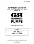
OM-01194-02
April 9, 1981
04-01-05 Rev. C
ABEGQ
INSTALLATION, OPERATION,
AND MAINTENANCE MANUAL
WITH PARTS LIST
0 SERIES PUMP
MODEL
03H1−GR
THE GORMAN-RUPP COMPANY D MANSFIELD, OHIO
www.gormanrupp.com
GORMAN-RUPP OF CANADA LIMITED D ST. THOMAS, ONTARIO, CANADA
eCopyright by the Gorman-Rupp Company
Printed in U.S.A.
TABLE OF CONTENTS
INTRODUCTION . . . . . . . . . . . . . . . . . . . . . . . . . . . . . . . . . . . . . . . . . . . . . . . . .
PAGE I − 1
SAFETY - SECTION A . . . . . . . . . . . . . . . . . . . . . . . . . . . . . . . . . . . . . . . . . . . .
PAGE A − 1
INSTALLATION − SECTION B . . . . . . . . . . . . . . . . . . . . . . . . . . . . . . . . . . . .
PAGE B − 1
Pump Dimensions . . . . . . . . . . . . . . . . . . . . . . . . . . . . . . . . . . . . . . . . . . . . . . . . . . . . .
PREINSTALLATION INSPECTION . . . . . . . . . . . . . . . . . . . . . . . . . . . . . . . . . . . . . . . . . . . .
POSITIONING PUMP . . . . . . . . . . . . . . . . . . . . . . . . . . . . . . . . . . . . . . . . . . . . . . . . . . . . . . .
Lifting . . . . . . . . . . . . . . . . . . . . . . . . . . . . . . . . . . . . . . . . . . . . . . . . . . . . . . . . . . . . . . . . .
Mounting . . . . . . . . . . . . . . . . . . . . . . . . . . . . . . . . . . . . . . . . . . . . . . . . . . . . . . . . . . . . .
SUCTION AND DISCHARGE PIPING . . . . . . . . . . . . . . . . . . . . . . . . . . . . . . . . . . . . . . . . .
Materials . . . . . . . . . . . . . . . . . . . . . . . . . . . . . . . . . . . . . . . . . . . . . . . . . . . . . . . . . . . . . .
Line Configuration . . . . . . . . . . . . . . . . . . . . . . . . . . . . . . . . . . . . . . . . . . . . . . . . . . . . . .
Connections to Pump . . . . . . . . . . . . . . . . . . . . . . . . . . . . . . . . . . . . . . . . . . . . . . . . . .
Gauges . . . . . . . . . . . . . . . . . . . . . . . . . . . . . . . . . . . . . . . . . . . . . . . . . . . . . . . . . . . . . . .
SUCTION LINES . . . . . . . . . . . . . . . . . . . . . . . . . . . . . . . . . . . . . . . . . . . . . . . . . . . . . . . . . . .
Fittings . . . . . . . . . . . . . . . . . . . . . . . . . . . . . . . . . . . . . . . . . . . . . . . . . . . . . . . . . . . . . . .
Strainers . . . . . . . . . . . . . . . . . . . . . . . . . . . . . . . . . . . . . . . . . . . . . . . . . . . . . . . . . . . . . .
Sealing . . . . . . . . . . . . . . . . . . . . . . . . . . . . . . . . . . . . . . . . . . . . . . . . . . . . . . . . . . . . . . .
Suction Lines In Sumps . . . . . . . . . . . . . . . . . . . . . . . . . . . . . . . . . . . . . . . . . . . . . . . . .
Suction Line Positioning . . . . . . . . . . . . . . . . . . . . . . . . . . . . . . . . . . . . . . . . . . . . . . . .
DISCHARGE LINES . . . . . . . . . . . . . . . . . . . . . . . . . . . . . . . . . . . . . . . . . . . . . . . . . . . . . . . .
Siphoning . . . . . . . . . . . . . . . . . . . . . . . . . . . . . . . . . . . . . . . . . . . . . . . . . . . . . . . . . . . . .
Valves . . . . . . . . . . . . . . . . . . . . . . . . . . . . . . . . . . . . . . . . . . . . . . . . . . . . . . . . . . . . . . . .
ALIGNMENT . . . . . . . . . . . . . . . . . . . . . . . . . . . . . . . . . . . . . . . . . . . . . . . . . . . . . . . . . . . . . .
SUCTION AND DISCHARGE PIPING . . . . . . . . . . . . . . . . . . . . . . . . . . . . . . . . . . . . . . . . .
Typical System Installation . . . . . . . . . . . . . . . . . . . . . . . . . . . . . . . . . . . . . . . . . . . . . .
Piping . . . . . . . . . . . . . . . . . . . . . . . . . . . . . . . . . . . . . . . . . . . . . . . . . . . . . . . . . . . . . . . .
Sealing . . . . . . . . . . . . . . . . . . . . . . . . . . . . . . . . . . . . . . . . . . . . . . . . . . . . . . . . . . . . . . .
Valves . . . . . . . . . . . . . . . . . . . . . . . . . . . . . . . . . . . . . . . . . . . . . . . . . . . . . . . . . . . . . . . .
Siphoning . . . . . . . . . . . . . . . . . . . . . . . . . . . . . . . . . . . . . . . . . . . . . . . . . . . . . . . . . . . . .
Eductors . . . . . . . . . . . . . . . . . . . . . . . . . . . . . . . . . . . . . . . . . . . . . . . . . . . . . . . . . . . . . .
OPERATION − SECTION C . . . . . . . . . . . . . . . . . . . . . . . . . . . . . . . . . . . . . .
PRIMING . . . . . . . . . . . . . . . . . . . . . . . . . . . . . . . . . . . . . . . . . . . . . . . . . . . . . . . . . . . . . . . . .
STARTING . . . . . . . . . . . . . . . . . . . . . . . . . . . . . . . . . . . . . . . . . . . . . . . . . . . . . . . . . . . . . . . .
Rotation . . . . . . . . . . . . . . . . . . . . . . . . . . . . . . . . . . . . . . . . . . . . . . . . . . . . . . . . . . . . . .
Drive . . . . . . . . . . . . . . . . . . . . . . . . . . . . . . . . . . . . . . . . . . . . . . . . . . . . . . . . . . . . . . . . .
OPERATION . . . . . . . . . . . . . . . . . . . . . . . . . . . . . . . . . . . . . . . . . . . . . . . . . . . . . . . . . . . . . .
Leakage . . . . . . . . . . . . . . . . . . . . . . . . . . . . . . . . . . . . . . . . . . . . . . . . . . . . . . . . . . . . . .
Liquid Temperature And Overheating . . . . . . . . . . . . . . . . . . . . . . . . . . . . . . . . . . . . .
Strainer Check . . . . . . . . . . . . . . . . . . . . . . . . . . . . . . . . . . . . . . . . . . . . . . . . . . . . . . . . .
Pump Vacuum Check . . . . . . . . . . . . . . . . . . . . . . . . . . . . . . . . . . . . . . . . . . . . . . . . . .
STOPPING . . . . . . . . . . . . . . . . . . . . . . . . . . . . . . . . . . . . . . . . . . . . . . . . . . . . . . . . . . . . . . . .
Cold Weather Preservation . . . . . . . . . . . . . . . . . . . . . . . . . . . . . . . . . . . . . . . . . . . . . .
GEARBOX TEMPERATURE CHECK . . . . . . . . . . . . . . . . . . . . . . . . . . . . . . . . . . . . . . . . . .
TROUBLESHOOTING − SECTION D . . . . . . . . . . . . . . . . . . . . . . . . . . . . . .
i
PAGE B − 1
PAGE B − 1
PAGE B − 2
PAGE B − 2
PAGE B − 2
PAGE B − 2
PAGE B − 2
PAGE B − 2
PAGE B − 2
PAGE B − 3
PAGE B − 3
PAGE B − 3
PAGE B − 3
PAGE B − 3
PAGE B − 3
PAGE B − 3
PAGE B − 4
PAGE B − 4
PAGE B − 4
PAGE B − 4
PAGE B − 5
PAGE B − 5
PAGE B − 6
PAGE B − 7
PAGE B − 7
PAGE B − 8
PAGE B − 8
PAGE C − 1
PAGE C − 1
PAGE C − 1
PAGE C − 1
PAGE C − 1
PAGE C − 2
PAGE C − 2
PAGE C − 2
PAGE C − 2
PAGE C − 2
PAGE C − 3
PAGE C − 3
PAGE C − 3
PAGE D − 1
TABLE OF CONTENTS
(continued)
PUMP MAINTENANCE AND REPAIR - SECTION E . . . . . . . . . . . . . . . . .
PERFORMANCE CURVE . . . . . . . . . . . . . . . . . . . . . . . . . . . . . . . . . . . . . . . . . . . . . . . . . . .
PARTS LIST:
Pump Model . . . . . . . . . . . . . . . . . . . . . . . . . . . . . . . . . . . . . . . . . . . . . . . . . . . . . . . . . .
PUMP AND SEAL DISASSEMBLY AND REASSEMBLY . . . . . . . . . . . . . . . . . . . . . . . . .
Removing Pump and Gearbox . . . . . . . . . . . . . . . . . . . . . . . . . . . . . . . . . . . . . . . . . . .
Pump Casing and Wear Ring Removal . . . . . . . . . . . . . . . . . . . . . . . . . . . . . . . . . . . .
Impeller Removal . . . . . . . . . . . . . . . . . . . . . . . . . . . . . . . . . . . . . . . . . . . . . . . . . . . . . .
Seal Removal and Disassembly . . . . . . . . . . . . . . . . . . . . . . . . . . . . . . . . . . . . . . . . . .
PUMP AND SEAL REASSEMBLY . . . . . . . . . . . . . . . . . . . . . . . . . . . . . . . . . . . . . . . . . . . .
Seal Reassembly and Installation . . . . . . . . . . . . . . . . . . . . . . . . . . . . . . . . . . . . . . . .
Impeller Installation . . . . . . . . . . . . . . . . . . . . . . . . . . . . . . . . . . . . . . . . . . . . . . . . . . . . .
Pump Casing and Wear Ring Installation . . . . . . . . . . . . . . . . . . . . . . . . . . . . . . . . . .
Installing Pump and Gearbox . . . . . . . . . . . . . . . . . . . . . . . . . . . . . . . . . . . . . . . . . . . .
GEARBOX DISASSEMBLY . . . . . . . . . . . . . . . . . . . . . . . . . . . . . . . . . . . . . . . . . . . . . . . . . .
GEARBOX REASSEMBLY . . . . . . . . . . . . . . . . . . . . . . . . . . . . . . . . . . . . . . . . . . . . . . . . . . .
LUBRICATION . . . . . . . . . . . . . . . . . . . . . . . . . . . . . . . . . . . . . . . . . . . . . . . . . . . . . . . . . . . . .
Seal Assembly . . . . . . . . . . . . . . . . . . . . . . . . . . . . . . . . . . . . . . . . . . . . . . . . . . . . . . . . .
Gearbox . . . . . . . . . . . . . . . . . . . . . . . . . . . . . . . . . . . . . . . . . . . . . . . . . . . . . . . . . . . . . .
ii
PAGE E − 1
PAGE E − 1
PAGE E − 3
PAGE E − 4
PAGE E − 4
PAGE E − 5
PAGE E − 5
PAGE E − 5
PAGE E − 5
PAGE E − 5
PAGE E − 7
PAGE E − 7
PAGE E − 8
PAGE E − 8
PAGE E − 9
PAGE E − 10
PAGE E − 10
PAGE E − 10
0 SERIES
OM-01194
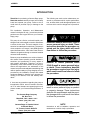
INTRODUCTION
Thank You for purchasing a Gorman-Rupp pump.
Read this manual carefully to learn how to safely
install and operate your pump. Failure to do so
could result in personal injury or damage to the
pump.
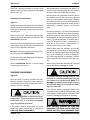
The following are used to alert maintenance personnel to procedures which require special attention, to those which could damage equipment, and
to those which could be dangerous to personnel:
This Installation, Operation, and Maintenance
manual is designed to help you achieve the best
performance and longest life from your GormanRupp pump.
This pump is an 0 Series, enclosed impeller, centrifugal model, with straight-in suction and without
a suction check valve. The basic material of construction for wetted parts is aluminum. The pump is
close-coupled to an integral, 1000 RPM gearbox
speed increaser with a 4.09:1 ratio. Power is transmitted to the gearbox through a customer-installed
universal shaft assembly.
Immediate hazards which WILL result in
severe personal injury or death. These
instructions describe the procedure required and the injury which will result
from failure to follow the procedure.
Because pump installations are seldom identical,
this manual cannot possibly provide detailed instructions and precautions for every aspect of
each specific application. Therefore, it is the responsibility of the owner/installer of the pump to
ensure that applications not addressed in this
manual are performed only after establishing that
neither operator safety nor pump integrity are compromised by the installation. Pumps and related
equipment must be installed and operated according to all national, local and industry standards.
Hazards or unsafe practices which
COULD result in severe personal injury
or death. These instructions describe
the procedure required and the injury
which could result from failure to follow
the procedure.
If there are any questions regarding the pump or
its application which are not covered in this manual or in other literature accompanying this unit,
please contact your Gorman-Rupp distributor, or
write:
The Gorman-Rupp Company
P.O. Box 1217
Mansfield, Ohio 44901−1217
Phone: (419) 755−1011
or:
Gorman-Rupp of Canada Limited
70 Burwell Road
St. Thomas, Ontario N5P 3R7
Phone: (519) 631−2870
INTRODUCTION
Hazards or unsafe practices which COULD
result in minor personal injury or product
or property damage. These instructions
describe the requirements and the possible damage which could result from failure
to follow the procedure.
NOTE
Instructions to aid in installation, operation, and
maintenance or which clarify a procedure.
PAGE I − 1
0 SERIES
OM-01194
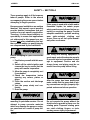
SAFETY − SECTION A
These warnings apply to 0 Series power
take-off pumps. Refer to the manual
accompanying the power source before
attempting to begin operation.
Because pump installations are seldom
identical, this manual cannot possibly
provide detailed instructions and precautions for each specific application.
Therefore, it is the owner/installer’s responsibility to ensure that applications
not addressed in this manual are performed only after establishing that neither operator safety nor pump integrity
are compromised by the installation.
Before attempting to open or service the
pump:
1. Familiarize yourself with this manual.
2. Switch off the vehicle ignition and
remove the key to ensure that the
pump will remain inoperative.
3. Allow the pump to completely cool
if overheated.
4. Check the temperature before
opening any covers, plates, or
plugs.
5. Close the suction and discharge
valves.
6. Vent the pump slowly and cautiously.
7. Drain the pump.
This pump is designed for vehicular
mounting in petroleum service. Do not
attempt to pump corrosive materials
which may damage the pump or endanger personnel as a result of pump failure.
SAFETY
If this pump is used with volatile and/or
flammable liquids, be certain proper
safety practices are followed before operating or servicing the pump. Provide
adequate ventilation, prohibit smoking,
wear static-resistant clothing and
shoes. Clean up all fuel spills immediately after occurrence.
Use lifting and moving equipment in
good repair and with adequate capacity
to prevent injuries to personnel or damage to equipment. Suction and discharge hoses and piping must be removed from the pump before lifting.
After the pump has been positioned,
make certain that the pump and all piping connections are tight, properly supported and secure before operation.
Do not operate the pump without the
shields and/or guards in place over the
rotating parts. Exposed rotating parts
can catch clothing, fingers, or tools,
causing severe injury to personnel.
PAGE A − 1
OM−01194
Do not operate the pump against a
closed discharge valve for long periods
of time. If operated against a closed discharge valve, pump components will
deteriorate, and the liquid could come
to a boil, build pressure, and cause the
pump casing to rupture or explode.
If this pump is used with volatile and/or
flammable liquids, overheating may
produce dangerous fumes. Take precautions to ensure the area surrounding
the pump is adequately ventilated. Allow the pump to cool and use extreme
caution when venting the pump, or
when removing covers, plates, plugs, or
fitting.
Overheated pumps can cause severe
burns and injuries. If overheating of the
pump occurs:
1. Stop the pump immediately.
2. Ventilate the area.
3. Allow the pump to completely cool.
4. Check the temperature before
opening any covers, plates,
gauges, or plugs.
5. Vent the pump slowly and cautiously.
6. Refer to instructions in this manual
before restarting the pump.
After the vehicle is positioned for pump
maintenance, block the wheels and set
the emergency brake before attempting
PAGE A − 2
0 SERIES
to disconnect the drive shaft or remove
the pump. Be sure the pump is properly
reinstalled and secure before operation.
Do not remove plates, covers, gauges,
pipe plugs, or fittings from an overheated pump. Vapor pressure within the
pump can cause parts being disengaged to be ejected with great force. Allow the pump to completely cool before
servicing.
The gearbox provided on this pump is
designed for operation at 1000 RPM
maximum input speed. If operated at a
higher RPM, pump components may be
destroyed.
Never run this pump backwards. Be certain that rotation is correct before fully
engaging the pump.
Never run the pump dry of pumping medium. There must be a supply of liquid to
the pump at all times to prevent destruction
of the shaft seal faces.
Pumps and related equipment must be installed and operated according to all national, local and industry standards.
SAFETY
0 SERIES
OM−01194
INSTALLATION − SECTION B
Review all SAFETY information in Section A.
Since pump installations are seldom identical, this
section offers only general recommendations and
practices required to inspect, position, and arrange the pump and piping.
Do not test or operate your pump and integral gearbox before reading the installation and operation instructions in
this manual.
This pump is a self-priming centrifugal model with
an integral gearbox assembly. It is designed for vehicular mounting in petroleum service, where the
liquid is supplied to the pump under pressure.
Since the pressure supplied to the pump is critical
to performance and safety, be sure to limit the in-
coming pressure to 50% of the maximum permissible operating pressure as shown on the pump performance curve (see Section E, Page 1).
The integral gearbox is designed to be driven
through the vehicle transfer case by a customersupplied universal shaft assembly. The pump casing or gearbox may be rotated in 45_ increments to
assist with alignment with the vehicle tank; however, if the gearbox is to be rotated, some modifications must be made to the gearbox to ensure adequate lubrication. Consult the factory for details.
For further assistance, contact your Gorman-Rupp
distributor or the Gorman-Rupp Company.
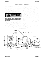
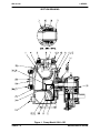
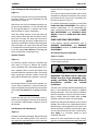
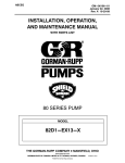
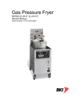
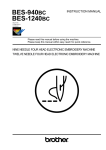
Pump Dimensions
See Figure 1 for the approximate physical dimensions of this pump.
OUTLINE DRAWING
Figure 1. Pump Model 03H1-GR
INSTALLATION
PAGE B − 1
OM−01194
PREINSTALLATION INSPECTION
The pump assembly was inspected and tested before shipment from the factory. Before installation,
inspect the pump for damage which may have occurred during shipment. Check as follows:
a. Inspect the pump and gearbox for cracks,
dents, damaged threads, and other obvious
damage.
b. Check for and tighten loose attaching hardware. Since gaskets tend to shrink after drying, check for loose hardware at mating surfaces.
c. Carefully read all tags, decals, and markings
on the pump assembly, and perform all duties
indicated. Note the direction of rotation indicated on the pump. Check that the pump
shaft rotates in the required direction.
Only operate this pump in the direction indicated on the pump body and/or the accompanying decal. Reverse rotation of the
shaft will adversely effect pump performance, and the pump and/or gearbox could
be seriously damaged.
d. Check levels and lubricate as necessary. Refer to LUBRICATION in the MAINTENANCE
AND REPAIR section of this manual and perform duties as instructed.
e. If the pump and gearbox have been stored for
more than 12 months, some of the components or lubricants may have exceeded their
maximum shelf life. These must be inspected
or replaced to ensure maximum pump service.
If the maximum shelf life has been exceeded, or if
anything appears to be abnormal, contact your
Gorman-Rupp distributor or the factory to determine the repair or updating policy. Do not put the
pump into service until appropriate action has
been taken.
PAGE B − 2
0 SERIES
VEHICLE REQUIREMENTS
The following instructions apply equally to new installations, rebuilds or retrofits.
Tank Preparation
It is essential that any tank scale, dirt, or other foreign material be removed from the tank and piping
prior to pump installation. Failure to do so could result in clogging or damage to the pump.
Damage to the pump resulting from debris
in the suction line will not be covered by
the pump warranty.
Before connecting the suction and discharge piping, carefully check the storage
tank and piping for construction debris
such as nuts, bolts, wire, weld slag, and
other foreign material. Install a commercially available 80 mesh screen in the suction line to prevent debris from entering the
pump.
POSITIONING PUMP
Lifting
Pump unit weights will vary depending on the
mounting and drive provided. Check the shipping
tag on the unit packaging for the actual weight, and
use lifting equipment with appropriate capacity.
Drain the pump and remove all customer-installed
equipment such as suction and discharge hoses
or piping before attempting to lift existing, installed
units.
INSTALLATION
0 SERIES
OM−01194
The pump assembly can be seriously
damaged if the cables or chains used to lift
and move the unit are improperly wrapped
around the pump.
Due to the confined mounting location,
specialized equipment such as a transmission jack with custom brackets should be
used to lift and position the pump and
gearbox.
NOTE
If the gearbox is rotated out of the standard position
shown in Figure 1, the oil fill and drain plugs must
be relocated. The oil vent must be relocated to the
highest port. Consult the factory for correct positioning of the fill plug to provide for proper lubrication of the gearbox.
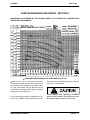
ALIGNMENT
When installing and/or aligning universal shaft assemblies, disconnect the
power source to ensure that the pump
will remain inoperative.
INSTALLATION
The alignment of the pump and its power source is
critical for trouble-free mechanical operation. Before checking alignment, make sure that the gearbox mounting bolts are tight.
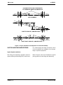
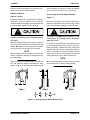
When connecting the universal joint drive shaft assembly to a PTO unit, install, support, and align the
drive shaft in accordance with the manufacturer’s
instructions. The pump and the drive power source
are generally positioned so that shaft centerlines
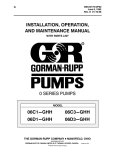
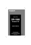
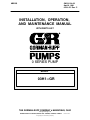
are parallel and horizontal. The maximum operating angle should not exceed 15 degrees (see Figure 3).
Check the direction of rotation of the PTO unit before starting the pump. The drive shaft must rotate
in the direction shown on the body of the pump,
gearbox, and/or decals, tags, and labels.
Do not operate the pump without the
guard in place over the rotating parts.
Exposed rotating parts can catch clothing, fingers, or tools, causing severe injury to personnel.
After the power take-off has been aligned, block
the wheels of the external power source, engage
the braking system, or take other precautions to
ensure that the power source will remain stationary. Block the wheels on the unit to prevent creeping.
PAGE B − 3
OM−01194
0 SERIES
LUGS MUST BE IN LINE, REGARDLESS
OF OPERATING ANGLE SHOWN BELOW
LUG ALIGNMENT
SHAFTS PARALLEL, ANGLES EQUAL
SHAFTS NOT PARALLEL, ANGLES EQUAL
Figure 3. Proper Installation And Alignment of Universal Assembly
SUCTION AND DISCHARGE PIPING
tors, related piping and safety accessories. Some
of the accessories are available from GormanRupp as optional equipment.
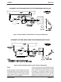
Typical System Installation
Tank filling and dispensing operations require a
system utilizing flow-directing (FDF) valves, educ-
PAGE B − 4
Refer to Figures 3 and 4 for illustrations of typical
piping systems for tank filling and dispensing.
INSTALLATION
0 SERIES
OM−01194
SCHEMATIC SYSTEM USING EDUCTOR FOR DISPENSING AND FILLING
Figure 3. Typical Installation Using Educator For Filling And Dispensing
SCHEMATIC SYSTEM USING PUMP FOR DISPENSING AND FILLING
Figure 4. Typical Installation Using Pump For Filling And Dispensing
Piping
All piping material must be compatible with the liquid being pumped. If hose is used in suction lines,
it must be the rigid-wall, reinforced type to prevent
collapse under suction. Using piping couplings in
suction lines is not recommended.
INSTALLATION
A suction strainer was not furnished with this pump
since it is not designed to handle liquids containing
solids. However, to protect the pump from accidental damage a commercially available 80 mesh
screen should be installed in the suction line. Make
certain that the total open area of the screen is at
least three or four times the cross section of the
PAGE B − 5
OM−01194
0 SERIES
suction line to ensure an adequate supply of liquid
to the pump.
Damage To the pump resulting from debris
in the suction line will not be covered by
the pump warranty.
Before connecting the suction and discharge piping, carefully check the storage
tank and piping for construction debris
such as nuts, bolts, wire, weld slag, and
other foreign material. Install a commercially available 80 mesh screen in the suction line to prevent debris from entering the
pump.
If a throttling valve is desired in the discharge line,
use a valve as large as the largest pipe to minimize
friction losses. Never install a throttling valve in a
suction line.
With high discharge heads, it is recommended that
a throttling valve and a system check valve be installed in the discharge line to protect the pump
from excessive shock pressure and reverse rotation when it is stopped.
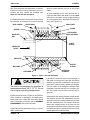
DISPENSING
POSITION
DISPENSE
Sealing
Since even a slight leak will affect priming, head,
and capacity, especially when operating with a
high suction lift, all connections in the suction line
should be sealed with pipe dope to ensure an airtight seal. Follow the sealant manufacturer’s recommendations when selecting and applying the
pie dope.
Valves
Gorman-Rupp manufactures several sizes of flowdiverting (FDF) valves for use in truck-mounted
pumping applications. The valves are designed to
reverse the flow of liquid with only the turn of a handle. This allows the same pump to fill or dispense
from the tank.
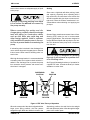
The FDF valve is designed for directing
flow only. it will not serve as a positive shutoff or throttling valve.
See Figure 5 illustrating the theory of operation for
a typical FDF valve. Consult the factory for further
assistance or other sizes.
FILL
POSITION
TOP VIEW
FILL
Figure 5. FDF Valve Theory of Operation
When the center web of the valve is aligned with the
larger ports (filling position), the flow passes
straight through. When the handle is turned to the
PAGE B − 6
dispensing position, the web blocks the straight
flow and opens two paths of flow through the larger
ports to the smaller ports.
INSTALLATION
0 SERIES
Siphoning
Do not terminate the discharge line at a level lower
than that of the liquid being pumped unless a siphon breaker is used in the line. Otherwise, a siphoning action causing damage to the pump
could result.
Eductors
An eductor may be used in conjunction with an
INSTALLATION
OM−01194
FDF valve to increase dispensing rates and improve efficiency. An educator may also be used to
collapse the tank service hose after the tank has
been filled or emptied.
Contact the Gorman-Rupp Company or an authorized distributor for specifications and performance data on eductors or FDF valves.
PAGE B − 7
OM−01194
0 SERIES
OPERATION − SECTION C
Review all SAFETY information in Section A.
Follow the instructions on all tags, labels and
decals attached to the pump.
This pump is designed for vehicular
mounting in petroleum service. Do not
attempt to pump corrosive materials, or
any liquids which may damage the
pump or endanger personnel as a result
of pump failure.
Add liquid to the pump casing when:
1. The pump is being put into service for the
first time.
2. The pump has not been used for a considerable length of time.
3. The liquid in the pump casing has evaporated.
When installed in a flooded suction application,
simply open the system valves and permit the incoming liquid to evacuate the air. After the pump
and piping system have completely filled, evacuate any remaining air pockets in the pump or suction line by loosening a pipe plug or opening bleeder valves.
Once the pump casing has been filled, the pump
will prime and reprime as necessary.
The gearbox provided on this pump is
designed for operation at 1000 RPM
maximum input speed. If operated at a
higher RPM, pump components may be
destroyed.
PRIMING
Install the pump and piping as described in INSTALLATION. Make sure that the piping connections are tight, and that the pump is securely
mounted. Check that the pump is properly lubricated (see LUBRICATION in MAINTENANCE
AND REPAIR).
This pump is self-priming, but the pump should
never be operated unless there is liquid in the
pump casing.
GROUNDING
To eliminate electrostatic build-up when pumping
petroleum products, the pump must be grounded
by attaching a ground wire to a ground rod. Install
the ground rod in accordance with the National
Electric Code and all local codes. Be sure the
clamp or fastener has made a tight electrical connection with the rod.
Inspect and test the ground wire assembly
for conductivity. Replace broken or frayed
wire before resuming operation.
STARTING
Consult the operations manual furnished with the
power source.
Never operate this pump unless there is
liquid in the pump casing. The pump will
not prime when dry. Extended operation of
a dry pump will destroy the seal assembly.
OPERATION
Rotation
The correct direction of pump rotation is counterclockwise when facing the input drive shaft. The
PAGE C − 1
OM−01194
pump could be damaged and performance adversely affected by incorrect rotation. If pump performance is not within the specified limits (see the
curve on Page E−1), check the direction of rotation
before further troubleshooting.
Drive
This pump is designed for operation with a power
take-off unit coupled to the drive shaft on the gearbox. The gearbox assembly has a ratio of 4.09:1,
and is designed for operation at 1000 RPM. Do not
operate at a higher input speed.
The gearbox provided on this pump is
designed for operation at 1000 RPM
maximum. If operated at a higher rpm,
pump components may be destroyed.
OPERATION
Pump speed and operating condition
points must be within the continuous performance range shown on the curve (see
Section E, Page 1).
Partially open the discharge throttling valve so that
the discharge line fills slowly to prevent damage to
piping, gaskets, and other devices in the line which
could be affected by shock resulting from rapid filling of the line. When the discharge line is completely filled, adjust the discharge throttling valve to
the desired flow rate.
Leakage
No leakage should be visible at pump mating surfaces, or at pump connections or fittings. Keep all
line connections and fittings tight to maintain maximum pump efficiency.
PAGE C − 2
0 SERIES
Liquid Temperature And Overheating
The maximum liquid temperature for this pump is
160_ F (71_C). Do not apply it at a higher operating
temperature.
Overheating can occur if operated with the valves
in the suction or discharge lines closed. Operating
against closed valves could bring the liquid to a
boil, build pressure, and cause the pump to rupture or explode. If overheating occurs, stop the
pump and allow it to cool before servicing it. Refill
the pump casing with cool liquid.
Allow an overheated pump to completely cool before servicing. Do not remove
plates, covers, gauges, pipe plugs, or
fittings from an overheated pump. Liquid within the pump can reach boiling
temperatures, and vapor pressure within the pump can cause parts being disengaged to be ejected with great force.
After the pump cools, drain the liquid
from the pump by removing the casing
drain plug. Use caution when removing
the plug to prevent injury to personnel
from hot liquid.
Strainer Check
If a suction strainer has been shipped with the
pump or installed by the user, check the strainer
regularly, and clean it as necessary. The strainer
should also be checked if pump flow rate begins to
drop. If a vacuum suction gauge has been installed, monitor and record the readings regularly
to detect strainer blockage.
Never introduce air or steam pressure into the
pump casing or piping to remove a blockage. This
could result in personal injury or damage to the
equipment. If backflushing is absolutely necessary, liquid pressure must be limited to 50% of the
maximum permissible operating pressure shown
on the pump performance curve. (See Section E,
Page 1.)
OPERATION
OM−01194
0 SERIES
Pump Vacuum Check
Since this pump does not have a suction check
valve, the discharge line must be fitted with a check
valve if a pump vacuum reading is to be taken.
With the pump inoperative, install a vacuum gauge
in the system, using pipe dope on the threads.
Block the suction line and start the pump. At operating speed the pump should pull a vacuum of 20
inches (508,0 mm) or more of mercury. If it does
not, check for air leaks in the seal, gasket, or discharge valve.
Open the suction line, and read the vacuum gauge
with the pump primed and at operation speed.
Shut off the pump. The vacuum gauge reading will
immediately drop proportionate to static suction
lift, and should then stabilize. If the vacuum reading
falls off rapidly after stabilization, an air leak exists.
Before checking for the source of the leak, check
the point of installation of the vacuum gauge.
NOTE
Petroleum products are very sensitive to changes
in temperature. Warmer temperatures elevate the
product vapor pressure, resulting in low vacuum
readings. Do not mistake temperature problems for
faulty pump installation or performance.
STOPPING
Never halt the flow of liquid suddenly. If the liquid
being pumped is stopped abruptly, damaging
shock waves can be transmitted to the pump and
piping system. Close all connecting valves slowly.
On engine driven pumps, reduce the throttle
speed slowly and allow the engine to idle briefly before stopping.
OPERATION
If the application involves a high discharge
head, gradually close the discharge
throttling valve before stopping the pump.
After stopping the pump, remove the engine ignition key to ensure that the pump will remain inoperative.
Cold Weather Preservation
If the application of this pump is limited to petroleum products, normal freezing conditions will not
damage the pump. However, during extremely severe conditions care should be exercised during
start-up, especially if the pump has been idle for
more than a few hours.
GEARBOX TEMPERATURE CHECK
The gearbox runs higher than ambient temperatures because of heat generated by friction. Temperatures of approximately 200_F (93_C) are considered normal, and can operate intermittently at
250_F (121_C).
Checking gearbox temperatures by hand is inaccurate. Place a contact-type thermometer against
the housing and record this temperature for future
reference.
A sudden increase in gearbox temperature is a
warning that the bearings are at the point of failing.
Make certain that the bearing lubricant is of the
proper viscosity and at the correct level (see LUBRICATION in Section E). Bearing overheating
can also be caused by shaft misalignment and/or
excessive vibration.
When pumps are first started, the bearings may
seem to run at temperatures above normal. Continued operation should bring the temperatures
down to normal levels within 20 minutes or less.
PAGE C − 3
0 SERIES
OM−01194
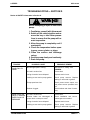
TROUBLESHOOTING − SECTION D
Review all SAFETY information in Section A.
Before attempting to open or service the
pump:
1. Familiarize yourself with this manual.
2. Switch off the vehicle ignition and remove the key, or take other precautions to ensure that the pump will remain inoperative.
3. Allow the pump to completely cool if
overheated.
4. Check the temperature before opening any covers, plates, or plugs.
5. Close the suction and discharge
valves.
6. Vent the pump slowly and cautiously.
7. Drain the pump.
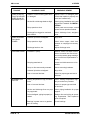
TROUBLE
PUMP FAILS TO
PRIME
PUMP STOPS OR
FAILS TO DELIVER
RATED FLOW OR
PRESSURE
TROUBLESHOOTING
POSSIBLE CAUSE
PROBABLE REMEDY
Not enough liquid in casing.
Add liquid to casing. See
PRIMING.
Air leak in suction line.
Correct leak.
Lining of suction hose collapsed.
Replace suction hose.
Leaking or worn seal or pump gasket.
Check pump vacuum. Replace
leaking or worn seal or gasket.
Pump speed too slow.
Check power source output; consult power source operation manual.
Strainer clogged.
Check strainer and clean if necessary.
Air leak in suction line.
Correct leak.
Suction intake not submerged at
proper level or sump too small.
Check installation and correct
submergence as needed.
Lining of suction hose collapsed.
Replace suction hose.
Leaking or worn seal or pump gasket.
Check pump vacuum. Replace
leaking or worn seal or gasket.
PAGE D − 1
OM−01194
TROUBLE
PUMP STOPS OR
FAILS TO DELIVER
RATED FLOW OR
PRESSURE (cont.)
PUMP REQUIRES
TOO MUCH
POWER
EXCESSIVE NOISE
BEARINGS RUN
TOO HOT
PAGE D − 2
0 SERIES
POSSIBLE CAUSE
PROBABLE REMEDY
Impeller or other wearing parts worn
or damaged.
Replace worn or damaged parts.
Check that impeller is properly centered and rotates freely.
Suction lift or discharge head too high.
Check piping installation and install
bypass line if needed. See INSTALLATION.
Pump speed too slow.
Check power source output; consult
power source operation manual.
Discharge line clogged or restricted;
hose kinked.
Check discharge lines; straighten
hose.
Universal joint drive misaligned.
Align drive.
Pump speed too high.
Check driver output; check that
sheaves or couplings are correctly
sized.
Discharge head too low.
Adjust discharge valve.
Cavitation in pump.
Reduce suction lift and/or friction
losses in suction line. Record vacuum and pressure gauge readings
and consult local representative or
factory.
Pumping entrained air.
Locate and eliminate source of air
bubble.
Pump or drive not securely mounted.
Secure mounting hardware.
Universal joint drive misaligned.
Align drive.
Low or incorrect lubricant.
Check for proper type and level of
lubricant.
Bearing temperature is high, but within
limits.
Check bearing temperature regularly to monitor any increase.
Low or incorrect lubricant.
Check for proper type and level
of lubricant.
Suction and discharge lines not properly supported.
Check piping installation for proper
support.
Drive misaligned; piping improperly installed.
Realign drive and piping at operating temperature. Add expansion
joints if required.
Bearings in power source or gearbox
worn or binding.
Check bearings.
TROUBLESHOOTING
0 SERIES
OM−01194
PREVENTIVE MAINTENANCE
Since pump applications are seldom identical, and
pump wear is directly affected by such things as
the abrasive qualities, pressure and temperature
of the liquid being pumped, this section is intended
only to provide general recommendations and
practices for preventive maintenance. Regardless
of the application however, following a routine preventive maintenance schedule will help assure
trouble-free performance and long life from your
Gorman-Rupp pump. For specific questions concerning your application, contact your GormanRupp distributor or the Gorman-Rupp Company.
Record keeping is an essential component of a
good preventive maintenance program. Changes
in suction and discharge gauge readings (if so
equipped) between regularly scheduled inspections can indicate problems that can be corrected
before system damage or catastrophic failure occurs. The appearance of wearing parts should also
be documented at each inspection for comparison
as well. Also, if records indicate that a certain part
(such as the seal) fails at approximately the same
duty cycle, the part can be checked and replaced
before failure occurs, reducing unscheduled down
time.
For new applications, a first inspection of wearing
parts at 250 hours will give insight into the wear rate
for your particular application. Subsequent inspections should be performed at the intervals shown
on the chart below. Critical applications should be
inspected more frequently.
Preventive Maintenance Schedule
Service Interval*
Item
General Condition (Temperature, Unusual
Noises or Vibrations, Cracks, Leaks,
Loose Hardware, Etc.)
Pump Performance (Gauges, Speed, Flow)
Bearing Lubrication
Seal Lubrication (And Packing Adjustment,
If So Equipped)
V-Belts (If So Equipped)
Air Release Valve Plunger Rod (If So Equipped)
Front Impeller Clearance (Wear Plate)
Rear Impeller Clearance (Seal Plate)
Check Valve
Pressure Relief Valve (If So Equipped)
Pump and Driver Alignment
Shaft Deflection
Bearings
Bearing Housing
Piping
Driver Lubrication − See Mfgr’s Literature
Daily
Weekly
Monthly
Semi- Annually
Annually
I
I
I
R
I
R
I
I
C
I
I
I
C
I
I
I
I
I
Legend:
I = Inspect, Clean, Adjust, Repair or Replace as Necessary
C = Clean
R = Replace
* Service interval based on an intermittent duty cycle equal to approximately 4000 hours annually.
Adjust schedule as required for lower or higher duty cycles or extreme operating conditions.
TROUBLESHOOTING
PAGE D − 3
0 SERIES
OM−01194
PUMP MAINTENANCE AND REPAIR - SECTION E
MAINTENANCE AND REPAIR OF THE WEARING PARTS OF THE PUMP WILL MAINTAIN PEAK
OPERATING PERFORMANCE.
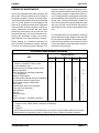
STANDARD PERFORMANCE FOR PUMP MODEL 03H1−GR
Based on 70_ F (21_ C) clear water corrected to
0.8 specific gravity at sea level with minimum suction lift. Since pump installations are seldom identical, your performance may be difference due to
such factors as viscosity, specific gravity, elevation,
temperature, and impeller trim.
If your pump serial number is followed by an N",
your pump is NOT a standard production model.
MAINTENANCE & REPAIR
Contact the Gorman-Rupp Company to verify performance or part numbers.
Pump speed and operating condition
points must be within the continuous performance range shown on the curve.
PAGE E − 1
OM−01194
0 SERIES
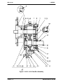
SECTION DRAWING
PARTS PAGE
Figure 1. Pump Model 03H1−GR
PAGE E − 2
MAINTENANCE & REPAIR
0 SERIES
OM−01194
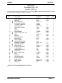
PARTS LIST
Pump Model 03H1−GR
(From S/N 287634 up)
If your pump serial number is followed by an N", your pump is NOT a standard production model. Contact
the Gorman-Rupp Company to verify part numbers.
ITEM
NO.
1
2
3
4
5
6
7
8
9
10
11
12
13
14
15
16
17
18
19
20
21
22
23
24
25
26
27
28
29
30
31
32
PART NAME
PART
NUMBER
MAT’L
CODE
QTY
PUMP CASING
IMPELLER
SEAL ASSEMBLY
DISCHARGE STICKER
FL HERE TO PRM STK
FILL PLUG ASSY
DISCHARGE FLANGE
STUD
HEX NUT
DISCH GASKET
PUMP CASING GSKT SET
STUD
HEX NUT
ROTATION DECAL
SEAL GUARD
SHAFT SLEEVE
SHAFT SLEEVE O-RING
GEARBOX ASSEMBLY
IMPELLER WASHER
IMPELLER KEY
NYLOCK CAPSCREW
LOCKWASHER
CASING DRAIN PLUG
WEAR RING
SUCT FLANGE GSKT
STUD
HEX NUT
SUCTION FLANGE
SUCTION STICKER
NAME PLATE
DRIVE SCREW
PIPE PLUG
8274A
8251A
25271−192
6588BJ
6588AH
48271−064
1390
C1009
D10
1318GB
3GC
C0605 1/2
D06
2613M
9834
9140
S1461
44161−014
6750
N0305−1/2
BT0604
J06
P20
62ZL5
1318GB
C1009
D10
1390
6588AG
38818−018
BM#04−03
P04
13040
13010
−−−
−−−
−−−
−−−
13040
15991
15991
20000
20010
15991
15991
−−−
14090
16000
−−−
−−−
13090
15990
15991
15991
11990
14000
20000
15991
15991
13040
−−−
13990
17000
15079
1
1
1
1
1
1
1
4
4
1
1
8
8
1
1
1
1
1
1
1
1
1
1
1
1
4
4
1
1
1
4
1
INDICATES PARTS RECOMMENDED FOR STOCK
MAINTENANCE & REPAIR
PAGE E − 3
OM−01194
0 SERIES
Figure 2. 44161−014 Gear Box Assembly
PAGE E − 4
MAINTENANCE & REPAIR
0 SERIES
OM−01194
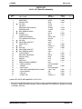
PARTS LIST
44161−014 Gear Box Assembly
ITEM
NO.
1
2
3
4
5
6
7
8
9
10
11
12
13
14
15
16
17
18
19
20
21
22
23
24
25
26
27
28
29
30
31
{
{
PART NAME
PART
NUMBER
MAT’L
CODE
WEAR RING
PINION SHAFT
OIL SEAL
AIR VENT
REDUCING PIPE BUSHING
SHIPPING PLUG
BALL BEARING #3306
GASKET
COVER PLATE
LUBRICATION DECAL
PTO LUBRICATION DECAL
OIL SEAL
ADJUSTING SHIM SET
DRIVE SHAFT
KEY
WDF KEY
ADJUSTING SHIM SET
BALL BEARING #3306
LOCK WASHER
HEX HEAD CAPSCREW
HELICAL GEAR
SPACER
PIPE PLUG
GEAR HOUSING ASSEMBLY
−GEAR HOUSING
−GASKET
−SEAL PLATE
−HEX HEAD CAPSCREW WITH FLANGE
−LOCK WASHER
−HEX NUT
−DOWEL PIN
62ZL6
8896
S1764
S1530
AP0602
11495A
S390
8871G
8871
38816−239
2613CO
S389
S464
8837
N0404 1/2
AV1210
S464
S390
J06
B0604
8895
9142
P06
8914
NOT AVAILABLE
8870G
NOT AVAILABLE
31871−065
J06
D06
AA0403 1/2
14000
16020
−−−
−−−
15079
15079
−−−
18000
10010
−−−
−−−
−−−
−−−
16040
15990
15990
−−−
−−−
15991
15991
16060
15990
15079
−−−
18000
15991
15991
15991
15990
QTY
1
1
1
1
1
1
2
1
1
1
1
1
1
1
1
1
1
2
6
6
1
1
5
1
1
1
1
8
8
8
2
INDICATES PARTS RECOMMENDED FOR STOCK
{ INDICATES THE MATING SURFACES OF ITEMS 25 AND 27 ARE MACHINED AT THE FACTORY FOR A
FLUSH FIT. THESE ITEMS ARE AVAIABLE ONLY BY ORDERING THE COMPLETE GEARBOX HOUSING
ASSEMBLY (ITEM 24).
MAINTENANCE & REPAIR
PAGE E − 5
OM−01194
PUMP AND SEAL DISASSEMBLY
AND REASSEMBLY
Review all SAFETY information in Section A.
Follow the instructions on all tags, label and decals attached to the pump.
This pump requires little service due to its rugged,
minimum-maintenance design. However, if it becomes necessary to inspect or replace the wearing
parts, follow these instructions which are keyed to
the sectional view (see Figures 1 and 2) and the accompanying parts list.
Most service functions, such as impeller, wear ring,
and seal replacement, may be performed by draining the pump and removing the pump casing.
However, due to the confined mounting location of
the pump, it is recommended that the pump and
gearbox be removed from the vehicle for service.
The following instructions assume complete disassembly is required.
0 SERIES
4. Check the temperature before
opening any covers, plates, or
plugs.
5. Close the suction and discharge
valves.
6. Vent the pump slowly and cautiously.
7. Drain the pump.
After the vehicle is positioned for pump
maintenance, block the wheels and set
the emergency brake before attempting
to disconnect the drive shaft or remove
the pump. Be sure the pump is properly
reinstalled and secured before operation.
Removing Pump and Gearbox
Due to the confined mounting location, it is recommended that the pump and gearbox be removed
from the vehicle for service.
If the gearbox requires repair, proceed with PUMP
AND SEAL DISASSEMBLY, followed by GEARBOX DISASSEMBLY.
Before attempting to service the pump, switch off
the engine ignition and remove the key, or take other safety precautions to ensure that it will remain
inoperative. Close all valves in the suction and discharge lines.
Before attempting to open or service the
pump:
1. Familiarize yourself with this manual.
2. Switch off the vehicle ignition and
remove the key, or take other precautions to ensure that the pump
will remain inoperative.
3. Allow the pump to completely cool
if overheated.
PAGE E − 6
The pump assembly can be seriously
damaged if the cables or chains used to lift
and move the unit are improperly wrapped
around the pump.
Due to the confined mounting location,
specialized equipment such as a transmission jack with custom brackets should be
used to lift and position the pump and
gearbox.
Close all valves in the suction and discharge lines.
Remove the pump casing drain plug (23) and drain
the pump.
Disconnect the P.T.O. shaft from the gearbox drive
shaft. Remove all the hardware securing the pump
and gearbox to the vehicle chassis. Tie and tag the
any leveling shims used under the casing mounting feet to ease reassembly. Move the pump and
gearbox to a clean, well-equipped shop for maintenance and repair.
MAINTENANCE & REPAIR
0 SERIES
OM−01194
Pump Casing and Wear Ring Removal
(Figure 1)
To service the impeller, wear ring or seal assembly,
the pump casing (1) must be separated from the
seal plate (27, Figure 2).
Remove the nuts (13) and separate the pump casing and casing gasket set (11) from the seal plate.
Tie and tag the gaskets, or measure and record
their thickness for ease of reassembly.
Clean the mating surfaces of the seal plate and
pump casing. Inspect the wear ring (24) for excessive wear or scoring. The wear ring is secured in
the pump casing by a press fit. If replacement is required, use a small bit to drill two holes through the
ring horizontally, 180_ apart. Use a saw and chisel
to complete the cuts through the ring, and remove
it from the casing. Use caution not to damage the
pump casing when removing the ring.
bellows. Slide the rotating portion of the seal off the
sleeve.
Use a pair of stiff wires with hooked ends to hook
the stationary element from the back side, and pull
the element and O-ring from the seal plate bore.
Remove the sleeve O-ring (17).
If no further disassembly is required, proceed with
PUMP AND SEAL REASSEMBLY. If the gearbox
requires disassembly, do not reassemble the
pump components at this time. Refer to GEARBOX DISASSEMBLY and GEARBOX REASSEMBLY, followed by PUMP AND SEAL REASSEMBLY.
PUMP AND SEAL REASSEMBLY
If the gearbox requires disassembly, refer to
GEARBOX DISASSEMBLY and GEARBOX
REASSEMBLY, followed by PUMP AND SEAL
REASSEMBLY.
Seal Reassembly and Installation
Impeller Removal
(Figures 1 and 3)
(Figure 1)
To loosen the impeller screw (21), immobilize the
drive shaft (14, Figure 2). Remove the impeller
screw, lockwasher (22), and impeller washer (19).
Use a suitable puller to remove the impeller from
the shaft. Retain the impeller key (20). Use caution
when removing the impeller; tension on the seal
spring will be released as the impeller is removed.
NOTE
An alternate method of removing the impeller is to
use two large screwdrivers on opposite sides between the impeller and seal plate to pry the impeller
off the shaft. Use caution not to damage the impeller.
Inspect the seal guard (15) for excessive wear or
scoring. The seal guard is secured on the impeller
by a press fit. If replacement is required, pull it off
the impeller.
Seal Removal and Disassembly
(Figure 1)
Carefully remove the seal spring. Remove the shaft
sleeve (16) and rotating portion of the seal as a
unit. Apply oil to the sleeve and work it up under the
MAINTENANCE & REPAIR
Clean the seal cavity and shaft with a cloth soaked
in fresh cleaning solvent.
Most cleaning solvents are toxic and
flammable. Use them only in a well-ventilated area free from excessive heat,
sparks, and flame. Read and follow all
precautions
printed
on
solvent
containers.
The seal is not normally reused because wear patterns on the finished faces cannot be realigned
during reassembly. This could result in premature
failure. If necessary to reuse an old seal in an emergency, carefully wash all metallic parts in fresh
cleaning solvent and allow to dry thoroughly.
Handle the seal parts with extreme care to prevent
damage. Be careful not to contaminate precision
finished faces; even fingerprints on the faces can
shorten seal life. If necessary, clean the faces with a
non-oil based solvent and a clean, lint-free tissue.
Wipe lightly in a concentric pattern to avoid
scratching the faces.
Inspect the seal components for wear, scoring,
grooves, and other damage that might cause leakPAGE E − 7
OM−01194
0 SERIES
age. Clean and polish the shaft sleeve, or replace it
if there are nicks or cuts on either end. If any components are worn, replace the complete seal;
never mix old and new seal parts.
If a replacement seal is being used, remove it from
the container and inspect the precision finished
SEAL GUARD
faces to ensure that they are free of any foreign
matter.
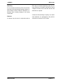
To ease installation of the seal, lubricate the Orings and shaft sleeve with water or a very small
amount of oil, and apply a drop of light lubricating
oil on the finished faces. Assemble the seal as follows, (see Figure E−3).
DRIVE BAND
SEAL PLATE
O-RING
SPRING
STATIONARY
SEAT AND SEAL
IMPELLER
KEY
SHAFT
SLEEVE
IMPELLER
SHAFT
IMPELLER
SLEEVE
O-RING
BELLOWS
ROTATING
ELEMENT
RETAINER
Figure 3. 25271−192 Seal Assembly
This seal is not designed for operation at
temperatures above 160_F (71_C). Do not
use at higher operating temperatures.
Inspect the pinion shaft (2, Figure 2) for distortion,
nicks, scratches, or damage to the shaft keyway.
Dress small nicks or burrs with a fine file or emery
cloth. If excessive wear exists, refer to GEARBOX
DISASSEMBLY and replace the shaft.
Lightly lubricate the shaft sleeve O-ring (17) and install it on the shaft.
PAGE E − 8
Lubricate the stationary seat O-ring with light oil
and install it in the groove in the seat. Use thumb
pressure to press this subassembly into the seal
plate until it seats squarely against the shoulder
bore. Be careful not to damage the seal face. After
installation, wipe the seal face in a concentric pattern with a clean, lint-free cloth to remove any fingerprints.
Subassemble the rotating element into the retainer
and bellows, and slide this subassembly over the
shaft sleeve until the rotating element is just flush
with the chamfered end of the sleeve. Slide the
sleeve and rotating portion of the seal onto the
shaft until the seal faces contact. Continue to push
the sleeve through the seal until the sleeve is fully
seated against the shaft shoulder.
MAINTENANCE & REPAIR
0 SERIES
OM−01194
and lockwasher (21 and 22). Torque the impeller
screw to 20 ft. lbs. (240 in. lbs. or 2,8 m. kg.).
Install the seal spring. Make sure that all components of the seal are seated squarely.
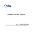
Impeller Installation
Pump Casing and Wear Ring Installation
(Figures 1 and 4)
(Figure 1)
Inspect the impeller (2), and replace it if cracked or
badly worn. If the seal guard (15) was removed,
press the replacement guard onto the impeller until
it seats squarely against the bore shoulder.
If the wear ring (24) was removed for replacement,
press the replacement ring into the pump casing
until it seats squarely against the shoulder bore.
The seal guard must seat squarely on the
impeller or binding and/or excessive wear
will result.
The wear ring must seat squarely in the
casing bore or binding and/or excessive
wear will result.
Align the impeller and key (20) with the shaft keyway, and press the impeller onto the shaft until fully
seated. Be sure the seal spring seats squarely
over the shoulder on the back of the impeller.
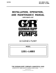
For maximum pump efficiency, the impeller should
be centered within the pump casing. To verify impeller positioning, measure the pump casing and
impeller as shown in Figure 4. Use these measurements to calculate the required impeller location
(dimension E). Add or remove gaskets in the pump
casing gasket set (44) to obtain dimension E.
NOTE
After the impeller has been installed, check for free
rotation. Correct any scraping or binding before further reassembly.
NOTE
Align the hole in the impeller washer (19) with the
key, and install the washer. Immobilize the drive
shaft (14, Figure 2), and install the impeller screw
C
When calculating pump casing positioning, figure
30% compression for pump casing gaskets.
D
D
2
B
2
A
E
B
Step 1
Step 2
A+
B
2
− C+ D
2
Step 3
=E
Figure 4. Centering Impeller Within Pump Casing
MAINTENANCE & REPAIR
PAGE E − 9
OM−01194
Install the calculated thickness of pump casing
gaskets. Secure the pump casing to the seal plate
with the nuts (33).
Installing Pump and Gearbox
(Figure 1)
Secure the pump and gearbox to the truck chassis
with the previously removed hardware. Be sure to
install any leveling shims used under the casing
mounting feet.
Reconnect the P.T.O. shaft the the gearbox drive
shaft and check the alignment as described in INSTALLATION, Section B.
Install the suction and discharge lines and open all
valves. Make certain that all piping connections are
tight, properly supported and secure.
Be sure the pump and gearbox have been properly lubricated (see LUBRICATION).
Fill the pump casing with clean liquid. Reinstall the
fill plug (6) and tighten it.
Refer to OPERATION, Section C, before putting
the pump back into service.
0 SERIES
Before attempting to disassemble the gearbox, remove the lower most pipe plug (23) and drain the
lubricant. Clean and reinstall the pipe plug.
With the pump end components removed, remove
the hardware (28, 29 and 30) securing the seal
plate (27) to the gearbox housing (25). Slide the
seal plate and oil seal (3) off the shaft. Remove the
seal plate gasket (26). Inspect the oil seal (3) and, if
replacement is required, press it form the seal
plate.
Remove the shaft key (15). Remove the hardware
(19 and 20) and slide the cover plate (9) and assembled oil seal (12) off the shaft. Remove the cover plate gasket (8) and bearing adjusting shims (13
and 17). Tie and tag the shims, or measure and record their thickness for ease of reassembly. Inspect the oil seal (12) and, if replacement is required, press it form the cover plate.
Slide the drive shaft (14), bearings (18 and 18A),
helical gear (21), pinion shaft (2) and bearings (7
and 7A) out of the seal plate side of the gear housing. It is not necessary to remove the dowel pins
(31) unless they are bent or damaged. If replacement is required, remove them from the gear housing.
After removing the shafts and bearings, clean and
inspect the bearings in place as follows.
GEARBOX DISASSEMBLY
(Figure 2)
When the pump is properly operated and maintained, the gearbox should not require disassembly. Disassemble the gearbox only when there is
evidence of wear or damage.
Gearbox disassembly in the field is not recommended. These operations should be
performed only in a properly equipped
shop by qualified personnel.
If the gearbox requires disassembly, first disassemble the pump components as indicated in
PUMP AND SEAL DISASSEMBLY.
PAGE E − 10
To prevent damage during removal from
the shaft, it is recommended that bearings
be cleaned and inspected in place. It is
strongly recommended that the bearings
be replaced any time the shaft and bearings are removed.
Clean the gear housing, seal plate, shafts and all
component parts (except the bearings) with a soft
cloth soaked in cleaning solvent. Inspect the parts
for wear or damage and replace as necessary.
Most cleaning solvents are toxic and
flammable. Use them only in a well-ventilated area free from excessive heat,
MAINTENANCE & REPAIR
0 SERIES
sparks, and flame. Read and follow all
precautions printed on solvent containers.
Clean the bearings thoroughly in fresh cleaning
solvent. Dry the bearings with filtered compressed
air and coat with light oil.
Bearings must be kept free of all dirt and
foreign material. failure to do so will greatly
shorten bearing life. Do not spin dry bearings. This may scratch the balls or races
and cause premature bearing failure.
Rotate the bearings by hand to check for roughness or binding and inspect the bearing balls. If rotation is rough or the bearing balls are discolored,
replace the bearings.
The bearing tolerances provide a tight press fit
onto the shafts and a snug slip fit into the gear
housing and seal plate. Replace the bearings,
shafts, gear housing, or seal plate if the proper
bearing fit is not achieved.
If the bearings, pinion shaft, or helical drive gear require replacement, use a suitable puller to remove
the bearings from the shafts. Slide the spacer (22)
and drive gear off the drive shaft. Retain the woodruff key (16).
GEARBOX REASSEMBLY
Clean and inspect the bearings as indicated in
GEARBOX DISASSEMBLY.
To prevent damage during removal from
the shaft, it is recommended that bearings
be cleaned and inspected in place. It is
strongly recommended that the bearings
be replaced any time the shaft and and
bearings are removed.
Inspect the helical gear (21) and pinion shaft (2) for
excessive wear or broken teeth and replace as required.
MAINTENANCE & REPAIR
OM−01194
Install the woodruff key (16) in the shaft keyway,
and slide the helical gear onto the shaft. Position
the spacer (22) against the inboard side of the helical gear.
The bearings (7, 7A, 18 and 18A) may be heated to
ease installation. An induction heater, hot oil bath,
electric oven, or hot plate may be used to heat the
bearings. Bearings should never be heated with a
direct flame or directly on a hot plate.
NOTE
If a hot oil bath is used to heat the bearings, both the
oil and the container must be absolutely clean. If
the oil has been previously used, it must be thoroughly filtered.
Heat the bearings to a uniform temperature no
higher than 250_F (120_C), and slide them onto
the shafts, one at a time, until they are fully seated.
This should be done quickly, in one continuous
motion, to prevent the bearings from cooling and
sticking on the shaft.
Use caution when handling hot bearings to prevent burns.
After the bearings have been installed and allowed
to cool, check to ensure that they have not moved
out of position in shrinking. If movement has occurred, use a suitably sized sleeve and a press to
reposition the bearings.
If heating the bearings is not practical, use a suitably sized sleeve and an arbor (or hydraulic) press
to install the bearings onto the shafts.
When installing the bearings onto the
shafts, never press or hit against the outer
race, balls, or ball cage. Press only on the
inner race.
If the dowel pins (31) were removed, install them in
the holes in the gear housing.
With the bearings, helical gear and spacer installed on the drive and pinion shafts, mesh the
PAGE E − 11
OM−01194
0 SERIES
teeth on the helical drive gear with those on the pinion shaft, and slide both shafts into the gear housing (25) until the outboard bearings are seated in
the bearing bores of the gear housing.
pump components are installed, lubricate the
gearbox as indicated in LUBRICATION.
If the oil seal (3) was removed, apply a light coating
of oil to the lip of the replacement seal, and position
it in the seal plate (27) with the lip positioned as
shown in Figure 2. Press the oil seal into the seal
plate until the inner side of the seal is just flush with
the inside of the seal plate.
Seal Assembly
Install the seal plate gasket (26), and slide the seal
plate over the inboard bearings. Align the holes in
the seal plate with the dowel pins (31), and secure
the seal plate to the gear housing with the hardware (28, 29 and 30).
If the oil seal (12) was removed, apply a light coating of oil to the lip of the replacement seal, and position it in the cover plate (9) with the lip positioned
as shown in Figure 2. Press the oil seal into the cover plate until the inner side of the seal is just flush
with the inside of the cover plate.
Position the cover plate gasket (9) against the gear
housing. Install the same thickness of bearing adjusting shims (13 and 17) as previously removed,
and slide the cover plate over the drive shaft.
Use caution not to damage the oil seal lip
on the shaft keyway when installing the
cover plate.
Secure the cover plate to the gear housing with the
hardware (19 and 20).
NOTE
Endplay for both the drive and pinion shafts should
be between .005 to.012 (0,127 to 0,305 mm). Add
or remove bearing shims to achieve the correct
endplay.
When the shaft endplay has been correctly established, remove the bottom three capscrews (20),
coat the threads with thread compound, and reinstall them in the gear housing.
Refer to PUMP AND SEAL REASSEMBLY and install the remaining pump components. After the
PAGE E − 12
LUBRICATION
The seal assembly is lubricated by the medium being pumped and no additional lubrication is required.
Gearbox
NOTE
The following instructions for gearbox lubrication
are based on the air vent (4) being positioned as
shown in Figure 2. If the gearbox is reconfigured
and the air vent moved to another position in the
gear housing, use caution not to over-lubricate the
gearbox.
The gearbox was fully lubricated when shipped
from the factory. Check the oil level regularly at the
oil level pipe plug(s) (not shown) midway down the
side of the gearbox. When lubrication is required,
add SAE 90 weight non-detergent gear oil through
the hole for the air vent (4). Fill the gearbox until the
oil level reaches the bottom of the pipe plug hole in
the face of the gear housing. Clean and reinstall the
air vent plug and the pipe plug. Do not over-lubricate. Over-lubrication can cause the bearings to
over-heat, resulting in premature bearing failure.
Under normal conditions, drain the gearbox once
each year. Add 1 ounce (29 ml) of ‘Molykote M’
Gear Guard, then fill with approximately 2 ounces
(59 ml) of SAE 90 weight non-detergent gear oil.
Change the oil more frequently if the pump is operated continuously or installed in an environment
with rapid temperature change.
Monitor the condition of the bearing lubricant regularly for evidence of rust or moisture condensation. This is especially important in areas where variable hot and
cold temperatures are common.
For cold weather operation, consult the factory or a
lubricant supplier for the recommended grade of
oil.
MAINTENANCE & REPAIR
AV−05397 (Rev 7−1−02)
GORMAN-RUPP PUMP
12 MONTH LIMITED WARRANTY
EXTENT AND DURATION OF WARRANTY
Coverage: The Gorman-Rupp Company or Gorman-Rupp of Canada Limited (herein individually referred
to as GR/GRC") each individually warrant that pumps made by it shall be free from defects in material and
workmanship for a period of twelve (12) months from the date of purchase by the original end user when
installation is made and use and maintenance is performed in accordance with GR/GRC’s recommendations. Wear and tear resulting from use and items normally consumed in use are not covered.
LIMITATIONS
GR/GRC’S SOLE AND EXCLUSIVE WARRANTY WITH RESPECT TO
PUMPS MADE BY IT IS THIS WARRANTY. THIS WARRANTY IS IN LIEU
OF ALL OTHER EXPRESS AND/OR IMPLIED WARRANTIES, INCLUDING
IMPLIED WARRANTIES OF MERCHANTABILITY AND FITNESS FOR
PARTICULAR PURPOSE.
EXCLUSIVE REMEDY AND DAMAGES
The sole and exclusive remedy for breach of this Warranty by GR/GRC, and the entire extent of its liability
for such breach or for damages arising from the use of the pump covered under this Warranty shall be as
follows:
1. Repair or replacement: If inspection shows that any GR/GRC pump covered under this Warranty is
defective in materials or workmanship, GR/GRC will repair or replace the defective pump or defective
part(s) thereof without charge, whichever GR/GRC chooses. You must have properly installed, maintained and used the pump or part claimed to be defective in accordance with the maintenance schedule and/or manual which comes with the pump. No allowance will be made for labor, transportation or
other charges incurred by you in connection with such repair or replacement.
2. To obtain the above remedy:
a) Immediately notify GR/GRC upon discovery of the claimed defect in materials or workmanship and
provide GR/GRC with the serial number or date code of the pump and the invoice or bill of sale
referencing the pump.
b) GR/GRC will advise whether inspection will be necessary and whether and how repair or replacement will be made. If inspection by GR/GRC is necessary, the pump or defective part(s) thereof
must be sent freight prepaid to GR/GRC. Return shipment will be F.O.B. GR/GRC’s plant.
3. Damages: GR/GRC’s liability for damages for breach of this Warranty shall not exceed the amount of
the purchase price of the defective part(s) thereof in respect to which damages are claimed.
IN NO EVENT SHALL GR/GRC BE LIABLE FOR INCIDENTAL,
CONSEQUENTIAL OR SPECIAL DAMAGES FOR BREACH OF THIS
WARRANTY.
THE GORMAN-RUPP COMPANY
P.O. BOX 1217
MANSFIELD, OH 44901−1217
Phone: (419) 755−1011
GORMAN-RUPP OF CANADA, LTD.
70 Burwell Road
St. Thomas, Ontario N5P 3R7
Phone: (519) 631−2870