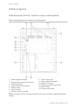
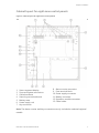
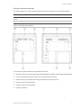
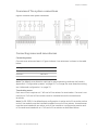
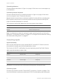
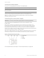
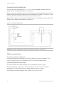
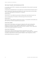
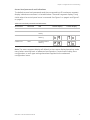
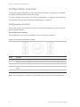
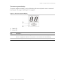
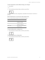
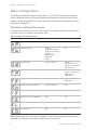
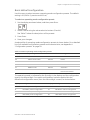
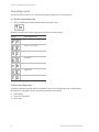
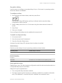
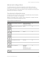
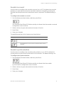
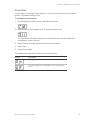
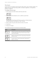
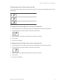
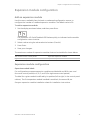
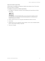
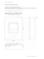
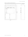
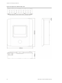
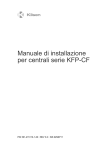
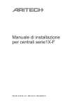
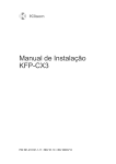
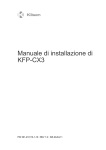
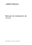
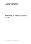
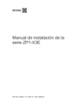
1
GE
Security
Kilsen KFP-CF Series Installation
Manual
P/N 501-415103-1-10 • REV 1.0 • ISS 03MAY09
Copyright
© 2009 GE Security, Inc.
This document may not be copied in whole or in part or otherwise reproduced without prior
written consent from GE Security, Inc., except where specifically permitted under US and
international copyright law.
Disclaimer
The information in this document is subject to change without notice. GE Security, Inc.
(“GE Security”) assumes no responsibility for inaccuracies or omissions and specifically disclaims
any liabilities, losses, or risks, personal or otherwise, incurred as a consequence, directly or
indirectly, of the use or application of any of the contents of this document. For the latest
documentation, contact your local supplier or visit us online at www.gesecurity.eu.
This publication may contain examples of screen captures and reports used in daily operations.
Examples may include fictitious names of individuals and companies. Any similarity to names
and addresses of actual businesses or persons is entirely coincidental.
Trademarks and patents
GE and the GE monogram are trademarks of General Electric Company. CleanMe and the Kilsen
KFP-CF Series name and logo are trademarks of GE Security.
Other trade names used in this document may be trademarks or registered trademarks of the
manufacturers or vendors of the respective products.
Intended use
Use this product only for the purpose it was designed for; refer to the data sheet and user
documentation for details. For the latest product information, contact your local supplier or visit
us online at www.gesecurity.eu.
Certification and compliance
European Union directives
2002/96/EC (WEEE directive): Products marked with this symbol cannot be disposed of as
unsorted municipal waste in the European Union. For proper recycling, return this product to
your local supplier upon the purchase of equivalent new equipment, or dispose of it at
designated collection points. For more information see: www.recyclethis.info.
2004/108/EC (EMC directive): Non-European manufacturers must designate an authorized
representative in the Community. Our authorized manufacturing representative is:
GE Security B.V., Kelvinstraat 7,
6003 DH Weert, The Netherlands.
2006/66/EC (battery directive): This product contains a battery that cannot be disposed of as
unsorted municipal waste in the European Union. See the product documentation for specific
battery information. The battery is marked with this symbol, which may include lettering to
indicate cadmium (Cd), lead (Pb), or mercury (Hg). For proper recycling, return the battery to your
supplier or to a designated collection point. For more information see: www.recyclethis.info.
Contact information
For contact information see our Web site: www.gesecurity.eu.
Content
Important information ii
Chapter 1 Introduction 1
Product range 2
Product compatibility 2
Operating modes 2
Chapter 2 Installation 3
Cabinet layout 4
Cabinet installation 6
Connections 8
Chapter 3 Configuration and commissioning 15
The user interface 16
Access levels and passwords 18
Configuration overview 20
Basic configuration 24
Advanced configuration 31
Expansion module configuration 39
Commissioning 42
Chapter 4 Maintenance 45
Fire alarm system maintenance 46
Battery maintenance 47
Chapter 5 Technical specifications 49
Appendix A Configuration presets 59
Operating mode presets 60
Expansion module presets 66
Appendix B Product compliance 69
Kilsen KFP-CF Series Installation Manual
i
Important information
This is the installation manual for the Kilsen KFP-CF series conventional fire control
panels. Read these instructions and all related documentation entirely before
installing or operating this product.
Limitation of liability
Installation in accordance with this manual, applicable codes, and the instructions of
the authority having jurisdiction is mandatory. GE Security shall not under any
circumstances be liable for any incidental or consequential damages arising from
loss of property or other damages or losses owing to the failure of GE Security
products beyond the cost of repair or replacement of any defective products. GE
Security reserves the right to make product improvements and change product
specifications at any time.
While every precaution has been taken during the preparation of this manual to
ensure the accuracy of its contents, GE Security assumes no responsibility for errors
or omissions.
ii
Kilsen KFP-CF Series Installation Manual
Chapter 1
Introduction
Summary
This chapter provides an introduction to your control panel and the available
operating modes.
Content
Product range 2
Product compatibility 2
Operating modes 2
Kilsen KFP-CF Series Installation Manual
1
Chapter 1: Introduction
Product range
The KFP-CF series includes the models shown below.
Model
Description
KFP-CF2
Two-zone conventional fire alarm control panel
KFP-CF4
Four-zone conventional fire alarm control panel with fire routing
KFP-CF8
Eight-zone conventional fire alarm control panel with fire routing
All models have been designed in accordance with EN 54-2, EN 54-4, BS 5839-1,
NBN S21-100, and NEN 2535 standards. For further details, see “Appendix B
Product compliance” on page 69.
Product compatibility
For details of compatible products, see the compatibility sheet included with your
control panel or consult your local supplier. Compatibility with other products cannot
be guaranteed.
Operating modes
Supported operating modes are shown in the table below. The default operating
mode is EN 54-2.
Table 1: Operating modes
Operating mode
Region
EN 54-2 (default)
European Union
EN 54-2 Evacuation
European Union (Spain)
EN 54-2 Scandinavia
European Union (Scandinavia)
BS 5839-1
United Kingdom
NBN S21-100
Belgium
NEN 2535
The Netherlands
2
Kilsen KFP-CF Series Installation Manual
Chapter 2
Installation
Summary
This chapter explains how to install your control panel, and how to connect zones, fire
system devices, and the power supply.
WARNING: This product must be installed and maintained by qualified personnel
adhering to the CEN/TS 54-14 standard (or the corresponding national standard) and
any other applicable regulations.
Content
Cabinet layout 4
Cabinet layout for two- and four-zone control panels 4
Cabinet layout for eight-zone control panels 5
Cabinet installation 6
Connections 8
Cabling requirements 8
Overview of fire system connections 9
Connecting zones and zone devices 9
Connecting inputs 10
Connecting outputs 11
Connecting the mains power supply 12
Selecting 115 or 230 VAC operation 13
Connecting the batteries 14
Other connections 14
Kilsen KFP-CF Series Installation Manual
3
Chapter 2: Installation
Cabinet layout
Cabinet layout for two- and four-zone control panels
Figure 1: Cabinet layout for two- and four-zone control panels
1.
2.
3.
4.
5.
6.
7.
Seven-segment display
Zone and fire system connectors
Cable knockouts
Mounting screw knockouts
Battery area
Key connector
Alarm counter connector
8. Power supply unit
9. Power supply connector
10. Battery connector
11. Expansion module connector
12. Cable holder
13. Fuse terminal block
Note: The alarm counter and key connectors are only included on selected regional
models.
4
Kilsen KFP-CF Series Installation Manual
Chapter 2: Installation
Cabinet layout for eight-zone control panels
Figure 2: Cabinet layout for eight-zone control panels
1.
2.
3.
4.
5.
6.
7.
Seven-segment display
Zone and system connectors
Cable knockouts
Mounting screw knockouts
Battery area
Power supply unit
Key connector
8. Alarm counter connector
9. Fuse terminal block
10. Power supply connector
11. Battery connector
12. Expansion module connector
13. Cable holder
Note: The alarm counter and key connectors are only included on selected regional
models.
Kilsen KFP-CF Series Installation Manual
5
Chapter 2: Installation
Cabinet installation
Before you begin
•
Remove the front cover
•
Remove cable knockouts from the top, bottom, and rear of the cabinet as
required
Where to install the cabinet
Make sure the installation location is free from construction dust and debris, and
immune to extreme temperature ranges and humidity (see “Chapter 5
Technical specifications” on page 49 for more information on the operating
temperature and relative humidity specifications).
Allow for enough floor and wall space so the panel can be installed and serviced
without any obstructions. The cabinet should be mounted so that the user interface is
at eye level.
6
Kilsen KFP-CF Series Installation Manual
Chapter 2: Installation
Fixing the cabinet to the wall
The requirements for nylon wall plugs and screws are shown in the following table.
Model
Screws
Wall plugs
Two- and four-zone control
panels
4 x M4, 30 mm
4 x Ø 6 mm
Eight-zone control panel
5 x M4, 30 mm
5 x Ø 6 mm
Figure 3: Mounting hole locations
Fix the control panel cabinet to the wall as follows:
1. Mark drill points on the wall using the template provided in the product packaging
2. Drill all required holes and insert a 6 mm wall plug into each.
3. Insert screw (1) half way and hang the cabinet onto this screw.
4. insert screws (2) and tighten.
5. Insert screws (3) and tighten.
6. Tighten screw (1).
Kilsen KFP-CF Series Installation Manual
7
Chapter 2: Installation
Connections
WARNING: Do not make any control panel or system connections while the control
panel is connected to the mains power supply.
Cabling requirements
Recommended cable
Recommended cables for your fire system are shown in the table below.
WARNING: Failure to use the recommended cable may impact system performance.
Table 2: Recommended cables
Cable
Cable description
Maximum cable length
Mains cable
3 x 1.5 mm
N/A
Zone circuit cable (mixed zone)
Twisted-pair (max. 40 Ω / 500 nF)
2 km
Zone circuit cable (automatic or
manual zones)
Twisted-pair (max. 55 Ω / 500 nF)
2 km
Securing cables
Use 20 mm cable glands to ensure clean and secure connections at the control panel
cabinet. All cables should be fed through the cable guides in the cabinet housing to
eliminate movement.
8
Kilsen KFP-CF Series Installation Manual
Chapter 2: Installation
Overview of fire system connections
Figure 4: Overview of fire system connections
Connecting zones and zone devices
Connecting zones
Connect zone wires as shown in Figure 4 above. Line resistance is shown in the table
below.
Zone type
Line resistance
Mixed (automatic and manual)
Max. 40 Ω
Automatic
Max. 55 Ω
Manual
Max. 55 Ω
Note: The default zone detection settings for each operating mode can be found in
Appendix A “Configuration presets” on page 59. To change the zone detection setting,
see “Advanced configuration” on page 31.
Terminating zones
Each zone circuit requires a 4.7 kΩ end-of-line resistor for termination. If a zone is not
used, the 4.7 kΩ end-of-line resistor must be installed across the unused zone
terminals.
Note: For BS 5839-1 the default zone configuration is active end-of-line and an active
end-of-line module must be installed instead of an end-of-line resistor. Unused zones
must be terminated with an active end-of-line module or configured as passive endof-line and terminated with a 4.7 kΩ end-of-line resistor as described above.
Kilsen KFP-CF Series Installation Manual
9
Chapter 2: Installation
Connecting detectors
Connect detectors as shown in Figure 4 on page 9. Each zone circuit can support up
to 20 detectors.
Connecting manual call points
Connect manual call points in parallel, as shown in Figure 4 on page 9. Each zone
circuit can support up to 32 manual call points.
Manual call points must have a resistance installed in series with the normally open
(NO) contact to avoid a short-circuit and to allow the control panel to identify the
origin of the alarm (automatic or manual).
The resistance required will depend on the zone type as shown below.
Zone type
Manual call point resistance
Mixed
100 Ω per 2 W
Manual
100 Ω to 470 Ω per 2 W
Note: The default zone detection settings for each operating mode can be found in
Appendix A “Configuration presets” on page 59. To change the zone detection setting,
see “Advanced configuration” on page 31.
Connecting inputs
Input functionality
Each control panel has two inputs, marked INPUT1 and INPUT2. These circuits are
connected as normally open and activated when closed.
The function of INPUT1 is defined by the panel operating mode. See Table 3 below.
Table 3: Input functionality for inputs 1 and 2
Operating mode
INPUT1
INPUT2
EN 54-2
Remote reset
Delays off
EN 54-2 Evacuation
Remote reset
Delays off
EN 54-2 Scandinavia
Extended fire routing delay
Delays off
BS 5839-1
Class change
Delays off
NBN S21-100
Remote reset
Delays off
NEN 2535
Fire routing inhibit delay
Delays off
Note: INPUT1 is not used in two-zone control panels operating EN 54-2 Scandinavia mode.
Connecting inputs
Connect input switches to INPUT1 and INPUT2, as shown in Figure 4 on page 9. The
circuit should have a maximum resistance of 100 Ω (including any cable resistance).
10
Kilsen KFP-CF Series Installation Manual
Chapter 2: Installation
Connecting outputs
Output functionality
Control panels have the following outputs:
•
Two-zone control panels have two outputs, marked OUT1 and OUT2.
•
Four- and eight-zone control panels have four outputs, marked OUT1, OUT2,
OUT3, and OUT4.
The function of each output is defined by the panel operating mode. See Table 4
below. All outputs are overload protected.
Table 4: Output functionality for outputs 1 to 4
Operating mode
OUT1
OUT2
OUT3
OUT4
EN 54-2
Sounders
Sounders
Sounders
Fire routing
EN 54-2 Evacuation
Sounders
Sounders
Sounders
Sounders
EN 54-2 Scandinavia
Sounders
Sounders
Sounders
Fire routing
BS 5839-1
Sounders
Sounders
Sounders
Sounders
NBN S21-100
Evacuation
sounders
Evacuation
sounders
Warning
sounders
Warning
sounders
NEN 2535
Sounders
Sounders
Fire routing
(automatic)
Fire routing
(manual)
Output termination
All outputs require a 15 kΩ end-of-line resistor for termination. If an output is not
used, the 15 kΩ end-of-line resistor must be installed across the unused output
terminals.
Output polarity
All outputs are polarity sensitive. Observe polarity or install a 1N4007 diode to avoid
inverted activation issues.
Connecting the sounders
Depending on the operating mode, up to four sounder circuits can be connected. See
Table 4 above.
The sounder outputs are powered and supply −15 VDC in standby and +24 VDC
(nominal value) in alarm.
The maximum current consumption for each sounder circuit is shown below.
Two- and four-zone control panels
250 mA
Eight-zone control panel
500 mA
The sounder outputs are supervised for short circuit and open circuit.
Kilsen KFP-CF Series Installation Manual
11
Chapter 2: Installation
Connecting fire routing equipment
Connect fire routing equipment as shown in the table below.
Operating mode
Fire routing (automatic)
Fire routing (manual)
EN 54-2
EN 54-2 Scandinavia
OUT4
OUT4
NEN 2535
OUT3
OUT4
The fire routing outputs are supervised for short circuit and open circuit.
Note: Fire routing in EN 54-2 operating modes makes no distinction between
automatic and manual alarms.
Connecting the mains power supply
WARNING: Connect the mains power supply before connecting the batteries.
The control panel can be operated at 110 VAC / 60 Hz or 240 VAC / 50 Hz
(+10%/−15%).
Mains power should be sourced directly from a separate circuit breaker in the
building electrical supply distribution board. This circuit should be clearly marked,
have a bipolar disconnect device, and only be used for fire detection equipment.
Feed all mains cables through the appropriate cable knockouts and connect them to
the fuse terminal block as shown in Figure 5 below.
Keep mains cables separate from other cabling to avoid potential short circuits and
interference. Always secure mains cables to the cabinet to prevent movement.
Figure 5: Connecting the mains power supply
1.
2.
3.
4.
Mains fuse
Live
Earth
Neutral
For fuse specifications, see Chapter 5 “Technical specifications” on page 49.
12
Kilsen KFP-CF Series Installation Manual
Chapter 2: Installation
Selecting 115 or 230 VAC operation
WARNING: An incorrect power setting can destroy the power supply.
Power switching for 115 or 230 VAC operation is automatic for two- and four-zone
control panels and no configuration is required.
For eight-zone control panels, the default power setting is 230 VAC. For 115 VAC
operation, use a small screwdriver to change the power setting switch, located on the
side of the power supply unit, as shown in Figure 6 below.
WARNING: Always disconnect the control panel from the mains supply before
changing the power setting.
Figure 6: Selecting 115 or 230 VAC operation
Kilsen KFP-CF Series Installation Manual
13
Chapter 2: Installation
Connecting the batteries
The control panel requires two 12 V, 7.2 or 12 Ah rechargeable, sealed, lead-acid
batteries (see “Compatible batteries” on page 47).
Batteries must be installed in series, at the base of the control panel cabinet. Use the
battery lead and bridge provided and connect batteries to the BATT connector on the
control panel PCB, as shown below. Polarity must be observed.
Note: If the control panel indicates a Supply Fault, then the batteries may need to be
replaced. See “Battery maintenance” on page 47.
Figure 7: Connecting the batteries
Caution: No other equipment may be connected to the BATT connector.
Other connections
Connecting auxiliary equipment
Connect the auxiliary equipment to 24 AUX as shown in Figure 4 on page 9. The
24 VDC auxiliary output is supervised for short circuit and voltage output.
Connecting alarm and fault relays
Connect the alarm and fault equipment to the ALARM and FAULT relays.
Each potential-free relay output will be activated in an alarm or fault situation
respectively. The fault relay output is powered when there is no fault.
The maximum contact rating for each relay circuit is 2 A / 30 VDC.
14
Kilsen KFP-CF Series Installation Manual
Chapter 3
Configuration and
commissioning
Summary
This chapter includes information on how to configure and commission the control
panel. Configuration is divided in basic configuration and advanced configuration
options.
Content
The user interface 16
User interface for two- and four-zone
control panels 16
User interface for eight-zone control
panels 17
Access levels and passwords 18
Configuration overview 20
Configuration controls 20
Common configuration tasks 22
Basic configuration 24
The basic configuration menu 24
Basic default configuration 25
Operating mode 26
Sounder delay 27
Fire routing delay 28
Extended fire routing delay 29
Add an expansion module 30
Advanced configuration 31
The advanced configuration
menu 31
Kilsen KFP-CF Series Installation Manual
Sounder operation during a zone
test 32
Sounder re-sound 33
Sounder synchronization 33
Zone configuration 34
Zone delay 35
Zone type 36
Changing access level passwords 37
Auxiliary 24 V reset 38
Configuration, software, and PCB
identification 38
Expansion module configuration 39
Add an expansion module 39
Expansion module configuration 39
Commissioning 42
Before commissioning the control
panel 42
Commissioning the control panel 42
Functional tests 44
Response times 44
15
Chapter 3: Configuration and commissioning
The user interface
User interface for two- and four-zone control panels
Figure 8: User interface for two- and four-zone control panels
1.
2.
3.
4.
5.
Zone buttons and LEDs (Z1, Z2, etc.)
Supply LED
General Fault LED
General Fire Alarm LEDs
Sounder Fault/Disable/Test button
and LED
6. Sounder Delay button and LED
7. Network Fault LED
8. Service Detector LED
9. Expansion I/O Fault/Disabled LED
10. General Disable button and LED
11. General Test button and LED
12. Configuration controls
13. Reset button and LED
14. Panel Silence button and LED
15. Sounder Start/Stop button and LED
16. System Fault LED
17. Out of Service LED
18. Earth Fault LED
19. Supply Fault LED
20. Fire Routing Delay button and LED
21. Fire Routing Start and
Fault/Disable/Test button and LEDs
Note: Two-zone control panels do not include fire routing.
16
Kilsen KFP-CF Series Installation Manual
Chapter 3: Configuration and commissioning
User interface for eight-zone control panels
Figure 9: User interface for eight-zone control panels
1.
2.
3.
4.
5.
Zone buttons and LEDs (Z1, Z2, etc.)
Supply LED
General Fault LED
General Fire Alarm LEDs
Sounder Fault/Disable/Test button
and LED
6. Sounder Delay button and LED
7. Network Fault LED
8. Service Detector LED
9. Expansion I/O Fault/Disabled LED
10. General Disable button and LED
11. General Test button and LED
Kilsen KFP-CF Series Installation Manual
12. Configuration controls
13. Reset button and LED
14. Panel Silence button and LED
15. Sounder Start/Stop button and LED
16. System Fault LED
17. Out of Service LED
18. Earth Fault LED
19. Supply Fault LED
20. Fire Routing Delay button and LED
21. Fire Routing Start and
Fault/Disable/Test button and LEDs
17
Chapter 3: Configuration and commissioning
Access levels and passwords
In accordance with EN 54-2, operation and configuration of this product is restricted
by access level.
Configuration tasks described in this chapter can only be performed at access level 3
basic or advanced. Passwords and indications for each access level are described in
“Access level passwords and indications” on page 19.
Access level 1
Access level 1 is the default access level and allows basic operational access only,
such as responding to a fire alarm or fault warning at the control panel.
Access level 2
Access level 2 allows advanced operational access. It is reserved for authorized users
who have been trained to operate the control panel.
Access level 3 basic
Access level 3 basic allows control panel configuration with rapid configuration
options for the most common installation requirements. It is reserved for the
installation contractors responsible for the fire system installation and configuration,
and for authorized maintenance contractors.
Access level 3 advanced
Access level 3 advanced allows control panel configuration with custom
configuration options for all installation requirements. It is reserved for the installation
contractors responsible for the fire system installation and configuration, and for
authorized maintenance contractors.
18
Kilsen KFP-CF Series Installation Manual
Chapter 3: Configuration and commissioning
Access level passwords and indications
The default access level passwords and the corresponding LED and seven-segment
display indications are shown in the table below. The seven-segment display is only
visible when the control panel cover is removed. See Figure 1 on page 4 and Figure 2
on page 5.
Table 5: Access level passwords and indications
Access level
Password
LED
Default display
Custom display
1
None
None
None
None
2
2222
The Reset LED is
steady
None
None
3 basic
3333
The Reset LED is
flashing
3 advanced
4444
The Reset LED is
flashing
Note: The seven-segment display will default to the custom display (operating mode
menu) when entering basic or advanced configuration if custom zone delay, zone
configuration, or zone type settings have been applied via the advanced
configuration menu.
Kilsen KFP-CF Series Installation Manual
19
Chapter 3: Configuration and commissioning
Configuration overview
To facilitate rapid configuration of the most common tasks, configuration is divided
into basic and advanced configuration levels.
For basic configuration options, see “Basic configuration” on page 24. For advanced
configuration options see “Advanced configuration” on page 31.
Configuration controls
The control panel is configured using the front panel configuration controls and the
seven-segment display.
The configuration controls
The configuration controls are located on the control panel interface.
Figure 10: Front panel configuration controls
Button
Function
1
Scroll to the next configuration menu on the seven-segment display.
2
Scroll to the next configuration value for the active menu on the seven-segment display.
3
Scroll to the previous configuration menu on the seven-segment display.
4
Scroll to the previous configuration value for the active menu on the seven-segment
display.
Enter
Confirm a menu selection or a value selection entry.
Note: The configuration controls are also used to enter the access level password.
20
Kilsen KFP-CF Series Installation Manual
Chapter 3: Configuration and commissioning
The seven-segment display
The seven-segment display is only visible when the control panel cover is removed
(see Figure 1 on page 4 and Figure 2 on page 5).
Figure 11: The seven-segment display
1. Mode LED
2. Value LED
LED
Indications
Mode
Select a configuration menu using buttons 1 and 3 when this LED is steady, or
Select a configuration submenu using buttons 1 and 3 when this LED is flashing.
Value
Select a configuration value using buttons 2 and 4 when this LED is steady
Kilsen KFP-CF Series Installation Manual
21
Chapter 3: Configuration and commissioning
Common configuration tasks
To enter configuration mode:
1. Remove the control panel cover so that the seven-segment display is visible.
2. Enter a valid access level 3 password (3333 for basic configuration or 4444 for
advanced configuration).
3. Press Enter.
When first entering configuration mode, the Mode LED on the seven-segment display
is steady. For other indications see “Access levels and passwords” on page 18.
To select a menu:
1. Select the required menu using the menu selection buttons (1 and 3).
2. Press Enter.
When a configuration menu has been selected, the Value LED on the seven-segment
display is steady.
To select a value:
1. Select the required value using the value selection buttons (2 and 4).
2. Press Enter.
To exit configuration mode and save your changes:
1. Press Panel Silence.
2. Press Enter.
— or —
1. Set the display as shown below, and then press Enter.
The Panel Silence LED flashes to confirm that a configuration change has been
applied.
Note: Make all required configuration changes before exiting configuration mode and
saving your changes.
22
Kilsen KFP-CF Series Installation Manual
Chapter 3: Configuration and commissioning
To exit configuration mode without saving your changes:
1. Press Reset
— or —
1. Set the display as shown below, and then press Enter.
The control panel will exit configuration mode after five minutes if no button is
pressed.
Visual indications for current value and selected value
Current and selected values are indicated as follows.
Status
Indication
Current value
Both decimal points on the
display are steady
New selected value
Both decimal points on the
display are flashing
Other value
Both decimal points on the
display are off
To restore the previous configuration:
1. Set the display as shown below, and then press Enter.
To restore the factory configuration:
1. Set the display as shown below, and then press Enter.
Kilsen KFP-CF Series Installation Manual
23
Chapter 3: Configuration and commissioning
Basic configuration
The default password for basic configuration is 3333. After entering the password,
the first displayed menu will be Basic default configuration (indicating level 3 basic
access) or Operating mode. For more information see “Access level passwords and
indications” on page 19.
The basic configuration menu
Configuration options for this menu are shown in the table below. More information
for each option is included in the related topic.
Table 6: The basic configuration menu
Display
Menu
Values
Operating mode
Basic default configuration
See topic
All
Operating mode
EN 54-2
EN 54-2 Evacuation
EN 54-2 Scandinavia
BS 5839-1
NBN S21-100
NEN 2535
Custom
All
Sounder delay
00 to 10 minutes
EN 54-2
EN 54-2 Evacuation
EN 54-2 Scandinavia
NBN S21-100
Fire routing delay
00 to 10 minutes
EN 54-2
EN 54-2 Scandinavia
NBN S21-100
NEN 2535
Extended fire routing delay
00 to 10 minutes
EN 54-2 Scandinavia
NEN 2535
Add an expansion module
00 to 04 modules
All
Restore previous configuration
N/A
All
Restore factory configuration
N/A
All
Exit without saving
N/A
All
Exit and save
N/A
All
Note: Additional menu options are available if one or more expansion modules are
installed. See “Expansion module configuration” on page 39.
24
Kilsen KFP-CF Series Installation Manual
Chapter 3: Configuration and commissioning
Basic default configuration
Use this menu to select common operating mode configuration presets. The default
setting is 01 (EN 54-2, passive end-of-line).
To select an operating mode configuration preset:
1. Set the display as shown below, and then press Enter.
2. Select a value using the value selection buttons (2 and 4).
See Table 7 below for descriptions of the presets.
3. Press Enter.
4. Save your changes.
A selected list of operating mode configuration presets is shown below. For a detailed
list of all available configuration presets and characteristics, see Appendix A
“Configuration presets” on page 59.
Table 7: Common operating mode configuration presets
Display
Operating mode
Zone end-of-line
Zone type
01 (default)
EN 54-2
Passive
Mixed
05
EN 54-2 Evacuation
Passive
Mixed
07
EN 54-2 Scandinavia
Passive
Mixed
11
BS 5839-1
Active
Mixed
21
NBN S21-100
Passive
Automatic
31
NEN 2535
Passive
Odd zones: Automatic
Even zones: Manual
The operating mode is indicated by the first digit in the display and the configuration
type by the second digit. If a custom configuration has been applied (via the
advanced configuration menu), then the second digit is a zero, as shown below.
Display
Configuration
Display
Configuration
01
EN 54-2 preset configuration
00
EN 54-2 custom configuration
11
BS 5839-1 preset configuration
10
BS 5839-1 custom configuration
21
NBN S21-100 preset configuration
20
NBN S21-100 custom configuration
31
NEN 2535 preset configuration
30
NEN 2535 custom configuration
Kilsen KFP-CF Series Installation Manual
25
Chapter 3: Configuration and commissioning
Operating mode
Use this read-only menu to view the operating mode of the control panel.
To view the operating mode:
1. Set the display as shown below, and then press Enter.
Display indications for each operating mode are shown below.
Display
Operating mode
EN 54-2
EN 54-2 Evacuation
EN 54-2 Scandinavia
BS 5839-1
NBN S21-100
NEN 2535
Custom
Custom operating mode
A custom operating mode will be indicated if any of the following zone configuration
settings are changed from the operating mode preset values:
•
•
•
26
Zone delay
Zone configuration
Zone type
Kilsen KFP-CF Series Installation Manual
Chapter 3: Configuration and commissioning
Sounder delay
Use this menu to configure a sounder delay of up to 10 minutes in operating modes
where the feature is available.
To configure a delay:
1. Set the display as shown below, and then press Enter.
The Sounder Delay LED flashes quickly to indicate that the sounder delay
configuration menu is active.
2. Select a delay value from 1 to 10 minutes using the value selection buttons (2
and 4).
3. Press Enter.
4. Save your changes.
Once configured the delay must be enabled at access level 2.
To enable a configured delay:
1. Exit access level 3.
2. Enter the access level 2 password.
3. Press the Sounder Delay button.
A steady Sounder Delay LED indicates that the delay is enabled.
Default delays
Default sounder delays for each operating mode are shown below.
Operating mode
Default delay in minutes
NBN S21-100
01
EN 54-2
EN 54-2 Evacuation
EN 54-2 Scandinavia
BS 5839-1
00
NEN 2535
This feature is not available in this operating mode.
Delay application logic
Depending on your fire alarm system configuration and the alarm activation device, a
configured delay may be overridden.
Delays will only be applied when:
•
The configured delay has been enabled.
•
The device reporting the fire alarm is a detector installed in a mixed or automatic
zone, OR a detector or manual call point installed in an automatic zone.
Kilsen KFP-CF Series Installation Manual
27
Chapter 3: Configuration and commissioning
•
The zone delay configuration is set to allow delays in the zone reporting the fire
alarm. (This is the default configuration.)
If any of the above are not true, then the control panel overrides the configured delay
and activates the sounders immediately.
Fire routing delay
Use this menu to configure a fire routing delay of up to 10 minutes in operating
modes where the feature is available.
To configure a delay:
1. Set the display as shown below, and then press Enter.
The Fire Routing Delay LED flashes quickly to indicate that the fire routing delay
configuration menu is active.
2. Select a delay value from 1 to 10 minutes using the value selection buttons (2
and 4).
3. Press Enter.
4. Save your changes.
Once configured the delay must be enabled at access level 2.
To enable a configured delay:
1. Exit access level 3.
2. Enter the access level 2 password.
3. Press the Fire Routing Delay button.
A steady Fire Routing Delay LED indicates that the delay is enabled.
Default delays
The default fire routing delay for each operating mode is shown below.
Operating mode
Default delay in minutes
EN 54-2 Scandinavia
01
NEN 2535
01
EN 54-2
00
EN 54-2 Evacuation
BS 5839-1
NBN S21-100
This feature is not available in these operating modes.
28
Kilsen KFP-CF Series Installation Manual
Chapter 3: Configuration and commissioning
Delay application logic
Depending on your fire alarm system configuration and the alarm activation device, a
configured delay may be overridden.
Delays will only be applied when:
•
The configured delay has been enabled.
•
The device reporting the fire alarm is a detector installed in a mixed or automatic
zone OR a detector or manual call point installed in an automatic zone.
•
The zone delay configuration is set to allow delays in the zone reporting the fire
alarm. (This is the default configuration.)
If any of the above are not true, then the control panel overrides the configured delay
and activates the fire routing immediately.
Extended fire routing delay
Use this menu to configure an extended fire routing delay of up to 10 minutes in
operating modes where the feature is available.
To configure an extended delay:
1. Set the display as shown below, and then press Enter.
The Fire Routing Delay LED flashes quickly to indicate that the fire routing delay
configuration menu is active.
4. Select a delay value from 1 to 10 minutes using the value selection buttons (2
and 4).
This value must be greater than the configured fire routing delay.
5. Press Enter.
6. Save your changes.
Once configured the delay is enabled at the same time as the standard fire routing
delay.
A steady Fire Routing Delay LED indicates that the all configured fire routing delays
are enabled.
Kilsen KFP-CF Series Installation Manual
29
Chapter 3: Configuration and commissioning
Default delays
The default extended fire routing delay for each operating mode is shown below.
Operating mode
Default delay in minutes
EN 54-2 Scandinavia
03
NEN 2535
03
EN 54-2
EN 54-2 Evacuation
BS 5839-1
NBN S21-100
This feature is not available in these operating modes.
Delay logic
Fire routing and extended fire routing delays elapse concurrently when a fire alarm
event is reported.
In NEN 2535 operating mode, the extended fire routing delay becomes the active
delay when sounders are stopped (by pressing the Sounder Start/Stop button) and
remain stopped when the standard fire routing delay time has elapsed.
In EN 54-2 Scandinavia operating mode, the extended fire routing delay becomes the
active delay when an extended fire routing delay switch (connected to INPUT1) is
activated while the standard fire routing delay elapses.
Extended delay application logic
Depending on your fire alarm system configuration and the alarm activation device, a
configured delay may be overridden.
Extended fire routing delays will only be applied when:
•
Both fire routing and extended fire routing delays are configured and enabled.
•
The operating mode requirements for the extended delay activation are true (see
the previous topic for differences in NEN 2535 and EN 54-2 logic).
•
The zone delay configuration is set to allow delays in the zone reporting the fire
alarm. (This is the default configuration.)
Add an expansion module
For information on how to add an expansion module to the fire system and how to
configure the module, see “Expansion module configuration” on page 39.
30
Kilsen KFP-CF Series Installation Manual
Chapter 3: Configuration and commissioning
Advanced configuration
The default password for advanced configuration is 4444. After entering the
password, the first displayed menu is Advanced default configuration (indicating
level 3 advanced access) or Operating mode. For more information see “Access level
passwords and indications” on page 19.
The advanced configuration menu
Configuration options for this menu are shown in the table below. More information
for each option is included in the related topic.
Note: All configurable options included in “Basic configuration” on page 24 are also
available from the advanced configuration menu.
Table 8: The advanced configuration menu
Display
Menu
Values
Operating mode
Advanced default configuration
Configuration presets, as
defined in “Basic default
configuration” on page 25
All
Sounder operation during a zone
test
ON/OFF
All
Sounder re-sound
ON/OFF
All
Sounder synchronization
ON/OFF
All
Software version
Read only
All
Configuration version
Read only
All
Configuration time stamp
Read only
All
Configuration date stamp
Read only
All
Zone configuration
Passive EOL
Active EOL
Unlatched
Passive EOL with CleanMe
Active EOL with CleanMe
All
Zone delay
ON/OFF
All
Kilsen KFP-CF Series Installation Manual
31
Chapter 3: Configuration and commissioning
Display
Menu
Values
Operating mode
Zone type
Mixed
Automatic
Manual
All
Access level 2 password
0 to 4444
All
Access level 3 basic password
0 to 4444
All
Access level 3 advanced
password
0 to 4444
All
Control panel PCB serial number
Read only
All
Auxiliary 24 V reset
ON/OFF
All
Sounder operation during a zone test
Use this menu to configure the sounder operation during a zone test. The default
setting for all operating modes is ON.
To configure the sounder operation during a zone test:
1. Set the display as shown below, and then press Enter.
The Sounders Start/Stop LED flashes quickly to indicate that the sounder
operation during a zone test configuration menu is active.
7. Select a value using the value selection buttons (2 and 4).
8. Press Enter.
9. Save your changes.
The available settings for this feature are shown below.
Display
Description
The internal buzzer and sounders sound for three seconds
when an alarm is activated in a zone test.
The internal buzzer and sounders do not sound when an
alarm is activated in a zone test.
32
Kilsen KFP-CF Series Installation Manual
Chapter 3: Configuration and commissioning
Sounder re-sound
Use this menu to configure the sounder re-sound, on or off. This determines sounder
operation in a fire alarm event when sounders have been silenced by pressing the
Sounder Start/Stop button and a new alarm event is reported. The default setting is
ON.
To configure the sounder re-sound:
1. Set the display as shown below, and then press Enter.
The Sounders Start/Stop LED flashes quickly to indicate that the sounder re-sound
configuration menu is active.
2. Select a value using the value selection buttons (2 and 4).
3. Press Enter.
4. Save your changes.
The available settings for this feature are shown below.
Display
Description
The sounders re-sound if a new fire alarm event is reported.
The sounders do not re-sound if a new fire alarm event is
reported.
Sounder synchronization
Use this menu to configure the sounder synchronization, on or off. This allows the
control panel to synchronize the activation of all sounders. The default setting is on.
To configure the synchronization:
1. Set the display as shown below, and then press Enter.
The Sounders Start/Stop LED flashes quickly to indicate that the sounder
synchronization configuration menu is active.
2. Select a value using the value selection buttons (2 and 4).
3. Press Enter.
4. Save your changes.
Kilsen KFP-CF Series Installation Manual
33
Chapter 3: Configuration and commissioning
The available settings for this feature are shown below.
Display
Description
The sounders are synchronized.
The sounders are not synchronized.
Zone configuration
Use this menu to configure zone settings for each zone in your fire alarm system. The
default setting for each operating mode is included in Appendix A “Configuration
presets” on page 59.
To configure the zone:
1. Set the display as shown below, and then press Enter.
2. Select the zone (for example, zone 1), and then press Enter.
The Zone fault/test/disable LED flashes quickly to indicate that the corresponding
zone configuration menu is active.
3. Select a value using the value selection buttons (2 and 4).
4. Press Enter.
5. Save your changes.
The available settings for this feature are shown below.
Display
Description
Passive end of line
Active end of line
Unlatched (only available in BS 5839-1 mode)
Passive end of line with CleanMe
Active end of line with CleanMe
34
Kilsen KFP-CF Series Installation Manual
Chapter 3: Configuration and commissioning
Zone delay
Use this menu to configure zone delays, on or off, for each zone in your fire alarm
system. The default setting is ON.
To configure the zone delay:
1. Set the display as shown below, and then press Enter.
2. Select the zone (for example, zone 1), and then press Enter.
The Zone alarm LED flashes quickly to indicate that the corresponding zone
configuration menu is active.
3. Select a value using the value selection buttons (2 and 4).
4. Press Enter.
5. Save your changes.
The available settings for this feature are shown below.
Display
Description
Configured delays are allowed in the corresponding zone.
Configured delays are not allowed in the corresponding
zone
Kilsen KFP-CF Series Installation Manual
35
Chapter 3: Configuration and commissioning
Zone type
Use this menu to configure the zone type for each zone in your fire alarm system. The
default setting for each operating mode is included in Appendix A “Configuration
presets” on page 59.
To configure the zone type:
1. Set the display as shown below, and then press Enter.
2. Select the zone (for example, zone 1), and then press Enter.
The Zone Fault/Test/Disable LED flashes quickly to indicate that the
corresponding zone configuration menu is active.
3. Select a value using the value selection buttons (2 and 4).
4. Press Enter.
5. Save your changes.
The available settings for this feature are shown below.
Display
Description
Mixed zone. The control panel automatically distinguishes
between an automatic alarm (generated by a detector) and
a manual alarm (generated by a manual call point fitted
with a 100 Ω resistor).
Automatic zone. All fire alarms are treated as reported by a
detector, even if the fire alarm is reported by a manual call
point in the zone.
Manual zone. All fire alarms are treated as reported by a
manual call point, even if the fire alarm is reported by a
detector in the zone.
36
Kilsen KFP-CF Series Installation Manual
Chapter 3: Configuration and commissioning
Changing access level passwords
Use the corresponding menu option (shown below) to change the default access level
passwords.
Access level 2 password
Access level 3 basic password
Access level 3 advanced password
To change the first two digits of an access level password:
1. Set the display for the desired access level password, and then press Enter.
2. Set the display as shown below, and then press Enter.
3. Select a value using the value selection buttons (2 and 4).
4. Press Enter.
5. Save your changes.
To change the last two digits of an access level password:
1. Set the display for the desired access level password, and then press Enter.
2. Set the display as shown below, and then press Enter.
3. Select a value using the value selection buttons (2 and 4).
4. Press Enter.
5. Save your changes.
Kilsen KFP-CF Series Installation Manual
37
Chapter 3: Configuration and commissioning
Auxiliary 24 V reset
Use this menu to configure the auxiliary 24 V reset setting, on or off. The default
setting is OFF.
To configure the zone delay:
1. Set the display as shown below, and then press Enter.
2. Select a value using the value selection buttons (2 and 4).
3. Press Enter.
4. Save your changes.
The available settings for this feature are shown below.
Display
Description
Resetting the control panel resets the AUX 24V output.
Resetting the control panel does not reset the AUX 24V
output.
Configuration, software, and PCB identification
Use the corresponding menu option (shown below) to see the control panel
configuration version and time stamp, software version, and PCB serial number.
These details may be required for troubleshooting and technical support.
Software version
Configuration version
Configuration time stamp
Configuration date stamp
Control panel PCB serial number
38
Kilsen KFP-CF Series Installation Manual
Chapter 3: Configuration and commissioning
Expansion module configuration
Add an expansion module
Use this menu, available from the basic or advanced configuration menus, to
configure the number of installed expansion modules. The default value is 00.
To add an expansion module:
1. Set the display as shown below, and then press Enter.
The Expansion I/O Fault/Disabled LED flashes quickly to indicate that the module
configuration menu is active.
2. Select a value using the value selection buttons (2 and 4).
3. Press Enter.
4. Save your changes.
The maximum number of expansion modules that can be installed is shown below.
Two- and four-zone control panels
Up to two expansion modules
Eight-zone control panel
Up to four expansion modules
Expansion module configuration
Expansion module labels
For configuration purposes expansion modules are labeled A and B (for two- and
four-zone control panels) or A, B, C, and D (for eight-zone control panels).
The label for a given module is defined by its position (left to right) in the control panel
cabinet,. The first expansion module installed is module A, the second B, etc.
See your expansion module installation sheet for installation instructions.
Kilsen KFP-CF Series Installation Manual
39
Chapter 3: Configuration and commissioning
Expansion module function and delay configuration
Once an expansion module is installed and added to the control panel configuration,
the following additional configuration options appear on the basic and advanced
configuration menus.
Note: These configuration options are repeated for each of the installed expansion
modules (A, B, C, and D).
Table 9: Expansion module A configuration options
Display
Description
Value
Module A function
00 to 92
Module A output 1 delay
00 to 10 minutes
Module A output 2 delay
00 to 10 minutes
Module A output 3 delay
00 to 10 minutes
Module A output 4 delay
00 to 10 minutes
Expansion module function
Use this menu to configure the expansion module function. The default value is 00.
For available presets, see Appendix A “Configuration presets” on page 59.
To configure the expansion module function:
1. Set the display as shown below, and then press Enter.
The Expansion I/O Fault/Disabled LED on the control panel interface and the ON
LED on the expansion module flashes quickly to indicate that the module function
configuration menu is active.
2. Select a value from 00 to 92 using the value selection buttons (2 and 4).
See Appendix A “Configuration presets” on page 59.
3. Press Enter.
4. Save your changes.
40
Kilsen KFP-CF Series Installation Manual
Chapter 3: Configuration and commissioning
Expansion module output delay
Use this menu to configure an expansion module output delay of up to 10 minutes,
where the feature is available.
To configure an expansion module output delay:
1. For output 1 on expansion module A, set the display as shown below, and then
press Enter.
The Expansion I/O Fault/Disabled LED on the control panel interface and the
Activated LED on the expansion module flashes quickly to indicate that the
module delay menu is active.
2. Select a value from 00 to 10 using the value selection buttons (2 and 4).
3. Press Enter.
4. Repeat steps 1 to 3 as required for each output (1 to 4) on each installed module
(A, B, C, and D) where a delay is required.
5. Save your changes.
Kilsen KFP-CF Series Installation Manual
41
Chapter 3: Configuration and commissioning
Commissioning
Before commissioning the control panel
Before commissioning the control panel, check the following:
•
That the control panel has been correctly installed
•
That the mains power is 110 VAC or 240 VAC, is connected correctly, and complies
with all requirements described in “Connecting the mains power supply” on page
12
•
That there are no short or open circuits in any of the zone circuits
•
That all zones have the correct end-of-line termination, as described in
“Terminating zones” on page 9
•
That all manual call points have the correct resistance for alarm identification, as
described in “Connecting manual call points” on page 10
•
That polarity is observed for all sounder circuits and that all end-of-line resistors
are installed, as described in “Connecting the sounders” on page 11
•
That any optional equipment installed (fire routing, alarm, and fault relays, etc.) is
correctly connected
•
That the batteries are connected correctly, and comply with all requirements
described in “Connecting the batteries” on page 14
•
That all fire alarm system configuration complies with the corresponding
operating mode and local regulations.
Commissioning the control panel
Once all installation, connection, and configuration requirements have been checked
as described above, the control panel can be powered up.
Normal start-up
After starting up the control panel, normal status (standby) is indicated as follows:
•
The Supply LED is steady
•
The Sounder Delay LED is steady (if a delay has been configured and enabled)
•
The Fire Routing Delay LED is steady (if a delay has been configured and enabled)
If any other indicators are on, check your installation thoroughly before proceeding.
42
Kilsen KFP-CF Series Installation Manual
Chapter 3: Configuration and commissioning
Fault start-up
In accordance with EN 54-2, the control panel has a special start-up sequence used
after an internal fault has been detected by the control panel.
This is indicated as follows:
•
•
The general Fault LED flashes quickly
The System Fault LED flashes slowly
When this happens:
1. Enter the access level 2 password.
2. Press the Reset button to reset the control panel.
If the fault status persists after reset, the control panel will abort the start-up
sequence and the System Fault LED will be steady.
When this happens, check all control panel connections and configuration, as
described in “Before commissioning the control panel” on page 42.
Battery start-up
To power up the control panel from the batteries, press the battery start button on
the control panel PCB (marked as BAT. START, see Figure 12 below). Keep the button
pressed for approximately five seconds.
Figure 12: Battery start-up button
Kilsen KFP-CF Series Installation Manual
43
Chapter 3: Configuration and commissioning
Functional tests
Create a short and open circuit in the zone to test fault reporting for each.
Activate a manual call point to test manual alarm reporting. The control panel should
override any configured delays and activate alarm notification devices and fire
routing (where applicable) immediately.
Activate a detector to test automatic alarm reporting. The control panel should
initiate any configured delays and activate alarm notification devices and fire routing
(where applicable) once the delay time has elapsed.
Using a multimeter, verify that the fault relay is activated when a fault is reported and
that the alarm relay is activated when an alarm is reported.
Response times
Response times for standard events are as follows.
Event
Response time
Alarm
Less than 3 seconds
Zone fault
Less than 30 seconds
Sounder fault
Less than 30 seconds
Fire routing fault
Less than 30 seconds
Earth fault
Less than 100 seconds
attery charger fault
Less than 100 seconds
Battery lost fault
Less than 3 minutes
Mains fault
Less than 3 minutes
Low battery fault
Less than 100 seconds
Fuse/protection fault
Less than 3 minutes
System fault
Less than 100 seconds
Battery high resistance fault
Less than 4 hours
44
Kilsen KFP-CF Series Installation Manual
Chapter 4
Maintenance
Summary
This chapter includes information on fire alarm system maintenance and battery
maintenance.
Content
Fire alarm system maintenance 46
Daily maintenance 46
Weekly maintenance 46
Quarterly maintenance 46
Annual maintenance 46
Cleaning the control panel 46
Battery maintenance 47
Kilsen KFP-CF Series Installation Manual
45
Chapter 4: Maintenance
Fire alarm system maintenance
Perform the following maintenance tasks to ensure that the fire alarm system works
correctly and complies with all required European regulations.
Caution: Before performing any tests, ensure that fire routing (if configured) is
disabled or that the fire brigade has been notified.
Daily maintenance
Check that the control panel is in standby. If it is not, investigate all system events
and/or fix any reported faults.
Weekly maintenance
Activate an alarm from at least one detector or manual call point in your fire alarm
system and verify that the control panel responds correctly to the alarm. If it does
not, investigate all system events and/or fix any reported faults.
Caution: Perform this test from a different detector or manual call point each time.
Quarterly maintenance
Test at least one device per zone and verify that the control panel responds to all
fault and alarm events. The control panel power supply and battery voltage should be
checked. Batteries with low voltage must be replaced (for more information see
“Battery maintenance” on page 47).
Annual maintenance
Test all system devices and verify that the control panel responds to all fault and
alarm events. All electrical connections must be visually inspected to make sure that
they are securely fastened, that they have not been damaged, and that they are
appropriately protected.
Cleaning the control panel
Keep the outside and inside of the control panel clean. Carry out periodic cleaning
using a damp cloth for the outside. Do not use products containing solvents to clean
the control panel. Do not clean the inside of the cabinet with liquid products.
46
Kilsen KFP-CF Series Installation Manual
Chapter 4: Maintenance
Battery maintenance
Compatible batteries
The control panel requires two 12V, 7.2 or 12 Ah rechargeable sealed lead-acid
batteries. Compatible batteries for this product are shown in the table below.
Table 10: Compatible batteries
Model
Battery type
Recommended batteries
Two- and four-zone
control panels
12V, 7.2 Ah
GE BS127N
Fiamm FG20721/2
Yuasa NP7-12
Eight-zone control panel
12V, 7.2 Ah or 12V, 12 Ah
GE BS127N (7.2 Ah)
GE BS130N (12 Ah)
Fiamm FG20721/2 (7.2 Ah)
Fiamm FG21201/2 (12 Ah)
Yuasa NP7-12 (7 Ah)
Yuasa NP12-12 (12 Ah)
Low battery indication
Battery supply and battery fuse faults are indicated by a flashing Supply Fault LED. If
this LED is flashing, check the following:
•
That the battery cables are in good condition
•
That the battery cables are connected securely and correctly at the battery and
at the control panel PCB
•
That the battery voltage is greater than 19.6 V
If the cables are in good condition and all connections are correct, then the batteries
should be replaced immediately.
Replacing batteries
Batteries must be replaced periodically as recommended by the battery
manufacturer. The useful life of the battery is approximately four years. Avoid the
total discharge of the batteries. Always use the recommended replacement batteries.
To replace the batteries:
1. Disconnect and remove the existing batteries from the cabinet.
2. Install and connect the replacement batteries using the bridge provided. Observe
correct polarity.
3. Dispose of the batteries as required by local or regional regulations.
Kilsen KFP-CF Series Installation Manual
47
Chapter 4: Maintenance
48
Kilsen KFP-CF Series Installation Manual
Chapter 5
Technical specifications
Summary
This chapter includes technical specifications for your fire alarm control panel.
Content
Zone circuit specifications 50
Input and output specifications 51
Power supply specifications 52
Mechanical and environmental specifications 53
Kilsen KFP-CF Series Installation Manual
49
Chapter 5: Technical specifications
Zone circuit specifications
General
Zone circuit output voltage
Nominal
Maximum
Minimum
22 VDC
24 VDC
18 VDC
Maximum current consumption per zone circuit
65 mA
Default zone circuit configuration
EN 54
NEN 2535
NBN S21-100
BS 5839-1
Passive end-of-line
Passive end-of-line
Passive end-of-line
Active end-of-line
Zone circuit termination
EN 54
NEN 2535
NBN S21-100
BS 5839-1
4.7 kΩ end-of-line resistor
4.7 kΩ end-of-line resistor
4.7 kΩ end-of-line resistor
Active end-of-line module
Number of detectors per zone circuit
Max. 20
Number of manual call points per zone circuit
Max. 32
Mixed zones
Maximum resistance per zone circuit
40 Ω
Maximum capacitance per zone circuit
500 nF
Nominal impedance
Detector
Manual call point
160 Ω to 470 Ω ±5%
100 Ω ±5%
Detector alarm reference range
Zone voltage
Zone impedance
6.5 V to 14 V
145 Ω to 470 Ω
Manual call point alarm reference range
Zone voltage
Zone impedance
3 V to 6.5 V
75 Ω to 144 Ω
Short circuit reference range
Zone voltage
Zone impedance
<3V
< 55 Ω
Open circuit reference range
Zone impedance
Zone device current consumption
> 8 kΩ
≤ 2.6 mA
Automatic and manual zones
Maximum resistance per zone circuit
55 Ω
Maximum capacitance per zone circuit
500 nF
Nominal impedance
100 Ω to 470 Ω ±5%
Detector alarm reference range
Zone voltage
Zone impedance
3 V to 14 V
75 Ω to 470 Ω
50
Kilsen KFP-CF Series Installation Manual
Chapter 5: Technical specifications
Automatic and manual zones
Short circuit reference range
Zone voltage
Zone impedance
<3V
< 55 Ω
Open circuit reference range
Zone impedance
Zone device current consumption
> 8 kΩ
≤ 2.6 mA
Input and output specifications
Inputs
Cable resistance
Activation input value
Deactivation input value
≤ 100 Ω
Open circuit
Outputs
Output termination
Sounder outputs
Supervised
Number of outputs
Maximum current per output (2-,4-zone)
Maximum current per output (8-zone)
Maximum voltage in standby
Maximum voltage in alarm
15 kΩ end-of-line resistor
For open and short circuit
4 (BS 5839-1, EN 54-2 Evacuation)
3 (EN 54-2, EN 54-2 Scandinavia)
2 (NEN 2535, NBN S21-100)
250 mA
500 mA
−15 VDC
+28 VDC
Fire routing outputs
Supervised
Number of outputs (EN 54)
Number of outputs (NEN 2535)
Maximum current per output (2-,4-zone)
Maximum current per output (8-zone)
Maximum voltage in standby
Maximum voltage in alarm
For open and short circuit
1
2
250 mA
500 mA
−15 VDC
+28 VDC
Alarm relay output
Number of potential-free outputs
Maximum commutation current
1
2 A at 30 VDC
Fault relay output
Number of potential-free outputs
Maximum commutation current
Default state
1
2 A at 30 VDC
Energized (fail to safe)
Auxiliary 24 VDC output
Nominal output voltage
Maximum output voltage
Minimum output voltage
Maximum current
24 VDC
28 VDC
21 VDC
250 mA
Kilsen KFP-CF Series Installation Manual
51
Chapter 5: Technical specifications
Power supply specifications
Mains supply
Operating voltage
110 VAC / 60 Hz or 240 VAC / 50 Hz
Rated current (two- and four-zone control panels)
110 VAC
240 VAC
2A
2A
Rated current (eight-zone control panels)
110 VAC
240 VAC
3.15 A
1.5 A
Voltage tolerance
+10% / −15%
Mains fuse
110 VAC
240 VAC
T 3.15A 250V
T 2A 250V
24 VDC power supply unit
Two- and four-zone control panels
DC voltage
Rated current
Current range
Rated power
Voltage tolerance
24 V
2A
0 to 2 A
50 W
±2%
Eight-zone control panel
DC voltage
Rated current
Current range
Rated power
Voltage tolerance
24 V
4A
0 to 4 A
100 W
±2%
Batteries and battery charger
Batteries
Two- and four-zone control panels
Eight-zone control panel
2 x 7.2 Ah
2 x 7.2 Ah or 2 x 12 Ah
Battery type
Sealed lead-acid
Battery charger voltage
27.3 V at 20ºC −36mV/ºC
Battery charger current
Two- and four-zone control panels
Eight-zone control panel
Max. 0.5 A
Max. 0.7 A
52
Kilsen KFP-CF Series Installation Manual
Chapter 5: Technical specifications
Mechanical and environmental specifications
Mechanical
Cabinet dimensions (no cover)
Two- and four-zone control panels
Eight-zone control panel
300 × 97 × 402 mm
421 × 100 × 447 mm
Weight without batteries
Two- and four-zone control panels
Eight-zone control panel
2.8 kg
3.9 kg
Number of cable knockouts
Two- and four-zone control panels
Eight-zone control panel
IP rating
14 x Ø 20 mm at top of cabinet
2 x Ø 20 mm at bottom of cabinet
12 x Ø 20 mm at rear of cabinet
20 x Ø 20 mm at top of cabinet
2 x Ø 20 mm at bottom of cabinet
26 x Ø 20 mm at rear of cabinet
IP30
Environmental
Operating temperature
Storage temperature
−5 to +40ºC
−5 to +70ºC
Relative humidity
10 to 95% (noncondensing)
Type class conditions
3K5 of IEC 60721-3-3
Note: For detailed cabinet drawings and dimensions, see “Cabinet drawings and
dimensions” on page 54.
Kilsen KFP-CF Series Installation Manual
53
Chapter 5: Technical specifications
Cabinet drawings and dimensions
Figure 13: Two- and four-zone cabinet with cover
54
Kilsen KFP-CF Series Installation Manual
Chapter 5: Technical specifications
Figure 14: Two- and four-zone cabinet without cover
Kilsen KFP-CF Series Installation Manual
55
Chapter 5: Technical specifications
Figure 15: Eight-zone cabinet with cover
56
Kilsen KFP-CF Series Installation Manual
Chapter 5: Technical specifications
Figure 16: Eight-zone cabinet without cover
Kilsen KFP-CF Series Installation Manual
57
Chapter 5: Technical specifications
58
Kilsen KFP-CF Series Installation Manual
Appendix A
Configuration presets
Summary
This appendix includes detailed information on operating mode and expansion
module configuration presets.
Content
Operating mode presets 60
EN 54-2 60
EN 54-2 Evacuation 61
EN 54-2 Scandinavia 62
BS 5839-1 63
NBN S21-100 64
NEN 2535 65
Expansion module presets 66
Expansion module zone configuration 66
Expansion module event configuration 68
Expansion module sounder circuit configuration 68
Kilsen KFP-CF Series Installation Manual
59
Appendix A: Configuration presets
Operating mode presets
EN 54-2
Configuration presets for EN 54-2 are as follows.
Two-zone control panels
Code
Zone EOL
Sounder outputs
Zone type
01
Passive
2
Mixed
02
Passive, CleanMe
enabled
2
Mixed
Note: CleanMe is not currently available for Kilsen detectors.
Four- and eight-zone control panels
Code
Zone EOL
Sounder outputs
Fire routing outputs Zone type
01
Passive
3
1
Mixed
02
Passive, CleanMe
enabled
3
1
Mixed
Additional configuration characteristics are shown below.
Default sounder delay
0
Default fire routing delay
0
Default zone delay
0n
Start/Restart sounders
Start sounders only if there is a fire alarm
Inputs and outputs are as follows.
INPUT1
Remote reset
INPUT2
Delays off
OUT1
Sounder circuit
OUT2
Sounder circuit
OUT3
Sounder circuit
OUT4
Fire routing
Note: Two-zone control panels have only two outputs (OUT1 and OUT2).
60
Kilsen KFP-CF Series Installation Manual
Appendix A: Configuration presets
EN 54-2 Evacuation
Configuration presets for EN 54-2 Evacuation are as follows.
Two-zone control panels
Code
Zone EOL
Sounder outputs
Zone type
05
Passive
2
Mixed
06
Passive, CleanMe
enabled
2
Mixed
Note: CleanMe is not currently available for Kilsen detectors.
Four- and eight-zone control panels
Code
Zone EOL
Sounder outputs
Zone type
05
Passive
4
Mixed
06
Passive, CleanMe
enabled
4
Mixed
Additional configuration characteristics are shown below.
Default sounder delay
0
Default zone delay
0n
Start/Restart sounders
Start sounders or restart stopped sounders at access level 2 with or
without a fire alarm event
Inputs and outputs are as follows.
INPUT1
Remote reset
INPUT2
Delays off
OUT1
Sounder circuit
OUT2
Sounder circuit
OUT3
Sounder circuit
OUT4
Sounder circuit
Note: Two-zone control panels have only two outputs (OUT1 and OUT2).
Kilsen KFP-CF Series Installation Manual
61
Appendix A: Configuration presets
EN 54-2 Scandinavia
Configuration presets for EN 54-2 Scandinavia are as follows.
Two-zone control panels
Code
Zone EOL
Sounder outputs
Zone type
07
Passive
2
Mixed
08
Passive, CleanMe
enabled
2
Mixed
Note: Note: CleanMe is not currently available for Kilsen detectors.
Four- and eight-zone control panels
Code
Zone EOL
Sounder outputs
Fire routing outputs Zone type
07
Passive
3
1
Mixed
08
Passive, CleanMe
enabled
3
1
Mixed
Additional configuration characteristics are shown below.
Default sounder delay
0
Default fire routing delay
0
Default extended fire routing
delay
0
Default zone delay
0n
Start/Restart sounders
Start sounders or restart stopped sounders at access level 2 with or
without a fire alarm event
Inputs and outputs are as follows.
INPUT1
Fire routing delay / extended fire routing
delay
INPUT2
Delays off
OUT1
Sounder circuit
OUT2
Sounder circuit
OUT3
Sounder circuit
OUT4
Fire routing
Note: INPUT1 is not used on two-zone control panels. Two-zone control panels
have only two outputs (OUT1 and OUT2).
62
Kilsen KFP-CF Series Installation Manual
Appendix A: Configuration presets
BS 5839-1
Configuration presets for BS 5839-1 are as follows.
Two-zone control panels
Code
Zone EOL
Sounder outputs
Zone type
11
Active
2 (first phase
evacuation mode)
Mixed
12
Active, CleanMe
enabled
2 (first phase
evacuation mode)
Mixed
13
Active
2 (second phase
evacuation mode)
Mixed
14
Active, CleanMe
enabled
2 (second phase
evacuation mode)
Mixed
Note: CleanMe is not currently available for Kilsen detectors.
Four- and eight-zone control panels
Code
Zone EOL
Sounder outputs
Zone type
11
Active
4 (first phase
evacuation mode)
Mixed
12
Active, CleanMe
enabled
4 (first phase
evacuation mode)
Mixed
13
Active
4 (second phase
evacuation mode)
Mixed
14
Active, CleanMe
enabled
4 (second phase
evacuation mode)
Mixed
Additional configuration characteristics are shown below.
Default sounder delay
0
Default zone delay
0n
Start/Restart sounders
Start sounders or restart stopped sounders at access level 2 with or
without a fire alarm event
Inputs and outputs are as follows.
INPUT1
Class change
INPUT2
Delays off
OUT1
Sounder circuit
OUT2
Sounder circuit
OUT3
Sounder circuit
OUT4
Sounder circuit
Note: Two-zone control panels have only two outputs (OUT1 and OUT2).
Kilsen KFP-CF Series Installation Manual
63
Appendix A: Configuration presets
NBN S21-100
Configuration presets for NBN S21-100 are as follows.
Four- and eight-zone control panels
Code
Zone EOL
Warning sounder
outputs
Evacuation sounder Zone type
outputs
21
Passive
2
2
Automatic
22
Passive, CleanMe
enabled
2
2
Automatic
Note: Alarm relay follows evacuation sounders. CleanMe is not currently available for Kilsen detectors.
Additional configuration characteristics are shown below.
Default sounder delay
1 minute
Default zone delay
0n
Start/Restart sounders
Start sounders or restart stopped sounders at access level 2 with or
without a fire alarm event
Inputs and outputs are as follows.
INPUT1
Remote reset
INPUT2
Delays off
OUT1
Evacuation sounders
OUT2
Evacuation sounders
OUT3
Warning sounders
OUT4
Warning sounders
64
Kilsen KFP-CF Series Installation Manual
Appendix A: Configuration presets
NEN 2535
Configuration presets for NEN 2535 are as follows.
Four- and eight-zone control panels
Code
Zone EOL
Sounder outputs
Fire routing outputs Zone type
31
Passive
2
2
Odd zones:
Automatic
Even zones:
Manual
32
Passive, CleanMe
enabled
2
2
Odd zones:
Automatic
Even zones:
Manual
Note: CleanMe is not currently available for Kilsen detectors.
Additional configuration characteristics are shown below.
Default fire routing delay
1 minute
Default extended fire routing
delay
3 minutes
Default zone delay
0n
Start/Restart sounders
Start sounders only if there is a fire alarm
Inputs and outputs are as follows.
INPUT1
Fire routing inhibit delay
INPUT2
Delays off
OUT1
Sounder circuit
OUT2
Sounder circuit
OUT3
Fire routing (automatic)
OUT4
Fire routing (manual)
Kilsen KFP-CF Series Installation Manual
65
Appendix A: Configuration presets
Expansion module presets
The following tables include the display settings for relay and supervised output
expansion module configuration presets.
Expansion module zone configuration
Relay expansion module
Supervised output expansion module
Display
Zone
Relay
Delay
Display
Zone
Output
Delay
01
1
1
Yes
51
1
1
Yes
2
2
Yes
2
2
Yes
3
3
Yes
3
3
Yes
4
4
Yes
4
4
Yes
5
1
Yes
5
1
Yes
6
2
Yes
6
2
Yes
7
3
Yes
7
3
Yes
8
4
Yes
8
4
Yes
1
1
Yes
1
1
Yes
2
Yes
2
Yes
3
Yes
3
Yes
4
Yes
4
Yes
1
Yes
1
Yes
2
Yes
2
Yes
3
Yes
3
Yes
4
Yes
4
Yes
1
Yes
1
Yes
2
Yes
2
Yes
3
Yes
3
Yes
4
Yes
4
Yes
1
Yes
1
Yes
2
Yes
2
Yes
3
Yes
3
Yes
4
Yes
4
Yes
1 or 2
1
Yes
1 or 2
1
Yes
3 or 4
2
Yes
3 or 4
2
Yes
5 or 6
3
Yes
5 or 6
3
Yes
7 or 8
4
Yes
7 or 8
4
Yes
02
05
2
06
3
4
07
5
6
08
7
8
13
66
52
55
2
56
3
4
57
5
6
58
7
8
63
Kilsen KFP-CF Series Installation Manual
Appendix A: Configuration presets
Relay expansion module
Supervised output expansion module
Display
Zone
Relay
Delay
Display
Zone
Output
Delay
15
1 and 2
1
Yes
65
1 and 2
1
Yes
3 and 4
2
Yes
3 and 4
2
Yes
5 and 6
3
Yes
5 and 6
3
Yes
7 and 8
4
Yes
7 and 8
4
Yes
1, 2, 3, or 4 1
Yes
1, 2, 3, or 4 1
Yes
5, 6, 7, or 8 2
Yes
5, 6, 7, or 8 2
Yes
Not used
3
N/A
Not used
3
N/A
Not used
4
N/A
Not used
4
N/A
1 and 2
1
Yes
1 and 2
1
Yes
2
Yes
2
Yes
3
Yes
3
Yes
4
Yes
4
Yes
1
Yes
1
Yes
2
Yes
2
Yes
3
Yes
3
Yes
4
Yes
4
Yes
17
18
3 and 4
19
5 and 6
7 and 8
Kilsen KFP-CF Series Installation Manual
67
68
3 and 4
69
5 and 6
7 and 8
67
Appendix A: Configuration presets
Expansion module event configuration
Relay expansion module
Supervised output expansion module
Display
Events
Relay
Delay
Display
Events
Output
Delay
24
Alarm
1-4
No
74
Alarm
1-4
No
25
Fault
1-4
No
75
Fault
1-4
No
26
Alarm
1-2
No
76
Alarm
1-2
No
Fault
3-4
No
Fault
3-4
No
Alarm
1
No
Alarm
1
No
Fault
2
No
Fault
2
No
Buzzer on
3
No
Buzzer on
3
No
Reset
4
No
Reset
4
No
28
Alarm
1-4
No
78
Alarm
1-4
No
29
Fault [1]
1-4
No
79
Fault [1]
1-4
No
30
Alarm
1-2
No
80
Alarm
1-2
No
Fault [1]
3-4
No
Fault [1]
3-4
No
Alarm
1
No
Alarm
1
No
Fault [1]
2
No
Fault [1]
2
No
Buzzer on
3
No
Buzzer on
3
No
Reset
4
No
Reset
4
No
27
31
77
81
[1] Positive security mode (output is on when there is no fault)
Expansion module sounder circuit configuration
Display
Events
Output
Delay
90 [1]
Sounder 1 circuit
1
No
2
No
3
No
4
No
1
No
2
No
3
No
4
No
1
No
2
No
3
No
4
No
Sounder 2 circuit
91
92 [1]
Sounder 1 circuit
Sounder 2 circuit
[1] NBN S21-100 only
68
Kilsen KFP-CF Series Installation Manual
Appendix B
Product compliance
European standards for fire control and indicating equipment
These control panels have been designed in accordance with European EN 54-2,
EN 54-4, BS 5839-1, NBN S21-100, and NEN 2535 standards.
In addition, all models comply with the following EN 54-2 optional requirements.
Option
Description
7.8
Output to fire alarm devices
7.9.1
Output to fire alarm routing equipment [1]
7.11
Delays to outputs
7.13
Alarm counter [2]
8.4
Total loss of the power supply
10
Test condition
11
Standardised input/output interface
[1] Excluding two-zone models.
[2] Dutch models only.
European standards for electrical safety and electromagnetic compatibility
These control panels have been designed in accordance with the following European
standards for electrical safety and electromagnetic compatibility:
•
•
•
•
•
EN 60950-1
EN 50130-4
EN 61000-6-3
EN 61000-3-2
EN 61000-3-3
Kilsen KFP-CF Series Installation Manual
69
Appendix B: Product compliance
70
Kilsen KFP-CF Series Installation Manual
Appendix B: Product compliance
Kilsen KFP-CF Series Installation Manual
71
Appendix B: Product compliance
72
Kilsen KFP-CF Series Installation Manual