1
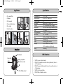
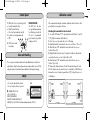
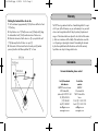
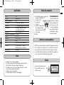
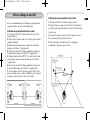
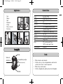
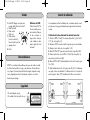
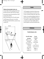
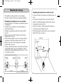
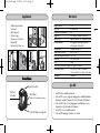
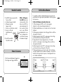
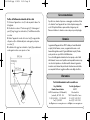
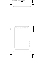
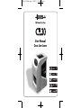
CL30-110x120.qxp
9/04/09
23:29
Page 1
User Manual
Cross Line Laser
PAGE
1
PAGE
8
PÁGINA
15
SEITE
22
PAGINA
29
CL30-110x120.qxp
9/04/09
23:29
Page 2
Applications
•
•
•
•
•
•
Floor and wall tiles
Wallpaper
Finish carpentry
Door and window frames
Drop ceilings
Interior decoration…
Recommended use
Leveling accuracy
Self-leveling range
Laser beams
Cross line
Manual mode
Power
Working temperature
Tripod mount
Size
Weight
Includes
Battery life
Overview
Control panel
Laser output
window
Battery compartment
(under rubber over-mold)
A
1/4” x 20 tripod mount
B
2
Specifications
Leveling
100 ft. (30 m)
± 1/8” @ 30’ (3 mm / 9 m)
± 4°
Highly visible 635 nm, Class 2 M
130° horizontal and vertical fan angles
Lock line to match any angle between two points
3 AA batteries 1,5 V
23° to 104° F (-5° to +40°C)
1/4’’ x 20 thread
3-1/2” x 3-1/4" x 2-1/2” (9 x 8,4 x 6,2 cm)
12 oz (340 g)
Belt carrying pouch, batteries
25 hrs. continuous use (1 line on),
12.5 hrs. continuous use (2 lines on)
Self-leveling
GB F E D
LED indications
• The LED is green in automatic mode.
• If the LED is red and the lasers blink in level or plumb mode, the laser is
out of leveling range.
• If the LED is green and the lasers blink in cross line mode, the laser is out
of leveling range.
• The LED is red in manual mode.
• If the LED blinks, the batteries are low.
3
CL30-110x120.qxp
9/04/09
23:29
Page 4
Calibration control
Control panel
1.
a.
b.
c.
d.
e.
ON button. Press to cycle through A-E:
Level (horizontal fan line)
Plumb (vertical fan line)
Cross line (horizontal and vertical)
Locked cross line (manual mode)
Off
2. LED for laser mode,
low battery
USING THE CL30
The CL30 cross line laser
uses a pendulum mechanism
for self-leveling. In order for
the unit to automatically
level, it must be set up within
4 degrees of level.
Care and Handling
This is a precision instrument which must be handled with care. Avoid shock
and vibrations. Keep the laser and aperture lens clean and dry. Use a soft cloth
and glass cleaner to clean them. Remove batteries before long-term storage.
Safety
• Do not stare directly at the beam.
• Do not set up the laser at eye level.
We recommend checking the instrument’s calibration before initial use; then
periodically to ensure proper reference.
Checking the horizontal line front to back
1. Set up the CL30 about 6” (15 cm) away from a wall (Surface 1) and 1215 ft. (4-5m) from another wall (Surface 2).
2. Turn it on in cross line mode. Be sure it's self-leveling.
3. Carefully mark the center where the lines cross on Surface 1. This is A1.
4. Rotate the laser 180° and mark the center where the lines cross on
Surface 2 (this is B1).
5. Right illustration: Move the laser 6” away from Surface 2 and mark the
center where the lines cross on Surface 2 (this is B2).
6. Rotate the laser 180° and mark the center where the lines cross on
Surface 1 (this is A2).
7. Measure the distance between A1 and A2, and also between B1 and
B2. If the distances are the same, the laser is in calibration. If the difference
between the two sets of marks is greater than 1/8” (3 mm), the laser is out
of calibration.
GB F E D
A
B COMPLIES WITH 21 CFR
1040.10 AND 1040.11
EXCEPT FOR DEVIATIONS
PURSUANT TO LASER NOTICE NO. 50
DATED JULY 26, 2001 AGATEC, 2202 Redmond Road Jacksonville, AR 72076
4
5
CL30-110x120.qxp
9/04/09
23:29
Page 6
Warranty
Checking the horizontal line side to side
1. Set the instrument up approximately 8’ (2.5m) from a wall that is at least
16’ (5m) long.
2. Project the laser cross 1’ (30cm) from one corner (1). Mark point (2) along
the horizontal laser line 8’ (2.5m) from the intersection of the laser cross.
3. Rotate the instrument so that the laser cross (3) is projected at the wall
15’ (4.6m) away from the first laser cross point (1).
4. The deviation of the horizontal laser line from the point (2) marked
previously should not be further apart than 1/8” or 3 mm.
The CL30 laser is guaranteed to be free of manufacturing defects for a period of 2 years (in North America, one year, with warranty to two years with
online or mail-in registration within 45 days of purchase). Any abnormal
usage or if the instrument has been subjected to shock will void this warranty. Under no circumstances will the liability of the manufacturer exceed the
cost of repairing or replacing the instrument. Disassembling the instrument
by other than qualified and certified technicians will void this warranty.
Specifications are subject to change without notice.
GB F E D
Information
For more information, please contact
6
For US, Canada and
Latin America
For all other
countries
AGATEC Construction Lasers
2202 Redmond Rd.,
Jacksonville, AR 72076 - USA
Tel. (800) 643-9696
(501) 982-4433
Fax (501) 982-0880
[email protected]
www.agatec-na.com
AGATEC
21 boulevard Littré
78600 Le Mesnil-le-Roi
France
Tél. +33 (0) 1 34 93 35 80
Fax +33 (0) 1 34 93 35 89
[email protected]
www.agatec.com
7
CL30-110x120.qxp
9/04/09
23:29
Page 8
Applications
•
•
•
•
•
•
•
Sol,
Cloison,
Tapisserie,
Finitions de menuiserie,
Agencement,
Huisserie, plafond suspendu,
Décoration intérieure…
GB F E D
Manuel d’utilisation
Laser Croix
Description
Clavier de commande
Fenêtre de sortie
des faisceaux
Compartiment à piles
(situé sous la protection
en gomme)
A
8
9
CL30-110x120.qxp
9/04/09
23:29
Page 10
Spécifications
Portée
Précision
Plage de compensation
Faisceau laser
Laser croix
Mode manuel
30 m
±3 mm à 9 m
± 4°
635 nm, visible, Classe 2M
130° de largeur d’angle horizontal et vertical
Verrouillage de la ligne pour s'aligner
sur un angle entre deux points
Alimentation
3 piles AA alcalines 1,5V
Température de fonctionnement -5° à +40°C
Filetage
1/4’’ x 20
Dimensions
9 x 8,4 x 6,2 cm
Poids
340 g
Inclus
Etui de ceinture, support aimanté, piles
Autonomie
25 h en continu pour 1 faisceau,
12h50 en continu pour 2 faisceaux
Mise à niveau
automatique
Clavier de commande
1. Bouton Marche. Appuyer sur celui-ci pour
naviguer des fonctions A à E :
a. Mode horizontal
b. Mode vertical
c. Mode croix
d. Utilisation en mode manuel
(hors calage automatique) :
faisceaux horizontal et vertical
e. Arrêt du laser
2. Diode
UTILISATION DU CL30
Le laser Croix CL30 utilise
un pendule pour sa mise à
niveau automatique. Afin
que le laser puisse se mettre à niveau automatiquement, il doit être installé à
un maximum de 4 degrés
du niveau horizontal.
GB F E D
Entretien et recommandations
Le CL30 est un instrument de précision qui doit être manipulé avec précaution et soin. Eviter le plus possible les chocs et les vibrations. Conservez le
sec et propre. Conserver la lentille de sortie du laser propre. La nettoyer
avec un chiffon doux et du nettoyant pour vitre. Otez les piles quand vous
ne vous servez pas du laser pendant une longue période.
Diode
• La diode est verte en mode automatique.
• Si la diode est rouge et que le faisceau clignote en mode horizontal ou
vertical, le laser n’est pas dans sa plage de compensation.
• Si la diode est verte et que le laser clignote en mode croix, le laser
n’est pas dans sa plage de compensation.
• La diode est rouge en mode manuel.
• Si la diode clignote, les batteries sont déchargées.
10
Sécurité
• Ne pas fixer directement le rayon.
• Ne pas installer le rayon à la
A
hauteur des yeux.
11
CL30-110x120.qxp
9/04/09
23:29
Page 12
Vérifier le calibrage de votre CL30
Nous vous recommandons de vérifier le calibrage de votre appareil avant
sa première utilisation ; puis de le vérifier périodiquement.
Vérification du niveau horizontal d’avant en arrière
1. Positionner votre CL30 à 15 cm d’un mur (Surface 1) et à 4-5 m d’un
autre mur (Surface 2).
2. Mettre le laser en marche en mode croix. S’assurer que le laser est dans
sa plage de nivellement.
3. Marquer alors minutieusement la position du point de croisement des
deux lignes sur la Surface 1. Il s’agit du point A1.
4. Faire pivoter le laser de 180°. Marquer également la position du point
de croisement des deux lignes sur la Surface 2. Il s’agit du point B1.
5. Illustration de droite : Installer le CL30 à 15 cm de la Surface 2 et marquer la position du point de croisement des deux lignes sur la Surface 2. Il
s’agit du point B2.
6. Faire pivoter le laser de 180°. Marquer également la position du point
de croisement des deux lignes sur la Surface 1. Il s’agit du point A2.
7. Mesurer la distance entre A1 et A2 ainsi qu’entre B1 et B2. Si les distances sont les même, le laser est calibré. Si la différence entre les deux jeux
de marques est supérieure à 3mm, le laser n’est pas calibré.
12
Vérification du niveau horizontal d’un côté à l’autre
1. Positionner votre CL30 à 2,5 m d’un mur long d’au moins 5m.
2. Projeter les faisceaux en mode croix à 30 cm d’un coin (1). Marquer le
point (2) le long de la ligne horizontale du laser à 2,5 m de l’intersection de
la croix du laser.
3. Faire pivoter le laser de sorte que la croix (3) soit projetée sur le mur à
4,6 m du premier point (1) de rencontre de la croix.
4. L’écart entre la ligne horizontale du laser et le point (2) marqué
précédemment ne doit pas être supérieur à 3 mm.
GB F E D
13
CL30-110x120.qxp
9/04/09
23:29
Page 14
Garantie
Votre CL30 est garanti contre tous défauts de fabrication et ce, pour une
période de 2 ans (1 an pour l'Amérique du Nord, la garantie est étendue à
2 ans si le produit est enregistré sur internet ou par courrier dans les 45
jours suivant l'achat). Un mauvais usage de l’appareil, un usage anormal ou
un choc entraînerait automatiquement la nullité de la garantie. En aucun
cas, la responsabilité du fabricant
n’excéderait le coût de réparation ou de remplacement de l’appareil. Le
démontage du CL30 par des personnes autres que des techniciens formés et
agréés entraînerait une annulation de la garantie. Les spécifications sont susceptibles de changer sans préavis.
GB F E D
Manual de utilización
Cross Line Láser
Renseignements
Pour tout renseignement contactez
14
Pour les USA, le Canada et
les pays d’Amérique Latine
Pour tous
les autres pays
AGATEC Construction Lasers
2202 Redmond Rd.,
Jacksonville, AR 72076 - USA
Tel. (800) 643-9696
(501) 982-4433
Fax (501) 982-0880
[email protected]
www.agatec-na.com
AGATEC
21 boulevard Littré
78600 Le Mesnil-le-Roi
France
Tél. +33 (0) 1 34 93 35 80
Fax +33 (0) 1 34 93 35 89
[email protected]
www.agatec.com
15
CL30-110x120.qxp
9/04/09
23:29
Page 16
Applicacions
•
•
•
•
•
•
•
Suelo
Tabique
Tapiz
Carpintería
Arreglo
Marco, sobre techo
Interiorismo…
Características
Alcance
Precisión
Nivelación
Diodo laser
Rayo
Pilas
Temperatura de uso
Fileteado
Dimensiones
Peso
Incluye
Tipo de nivelación
Hasta 30m (100 ft.)
±3 mm a 9 m (1/8” a 30’)
± 4°
635 nm, visible, Clase 2M
130° de amplitud horizontal y vertical
3 pilas AA alcalinas 1,5V
-5° hasta +40°C (23° hasta 104° F)
1/4’’ x 20
9 x 8,4 x 6,2 cm (3-1/2" x 3-1/4" x 2-1/2")
340 g (12 oz)
25 h en continuo para 1 línea,
12h50 en continuo para 2 líneas
Automática
GB F E D
Descripción
Teclado
Ventana de
salida del rayo
Compartimento para pilas
(debajo de la protección)
A
Diodo
• El diodo está verde en modo automático.
• Si el diodo está rojo y si el rayo está parpadeando en modo horizontal
o vertical, el láser no está en su zona de compensación.
• El diodo está rojo en modo manual.
• Si el diodo está parpadeando, significa que las pilas están descargadas.
Fileteado
16
17
CL30-110x120.qxp
9/04/09
23:29
Page 18
Teclado
Control de calibración
1. Botón ON. Empujar ese botón para
navegar desde la función A hasta E :
a. Modo horizontal
b. Modo vertical
c. Modo cruz
d. Modo manual
(sin auto nivelación) :
línea horizontal y vertical.
e. Apagar el láser
Utilización del CL30
El láser de línea CL30 utiliza un péndulo para su
auto nivelación. Para que
la auto nivelación se
haga, el láser tiene que
estar instalado a máximum 4 grados del nivel
horizontal.
2. Diodo
Recomendaciones
El CL30 es un instrumento de medida que tiene que estar usado con cuidado. Evitar lo más posible los choques y las vibraciones. Conservarlo bien
seco y limpio. Conservar la lente del láser bien limpio. Limpiarla con algo
suave y limpiador para cristal. Sacar las pilas cuando no use el láser
durante un periodo largo.
Le recomendamos verificar la calibración de su instrumento antes de usarlo
por primera vez y luego periódicamente para asegurarse de la referencia
correcta.
Verificación de la línea horizontal de adelante hacia atrás
1. Colocar el CL30 a 15cm (6”) de una pared (superficie 1) y a 4-5m (1215 ft.) de otra (superficie 2).
2. Encender el CL30 en modo cruzado. Asegurarse que este auto nivelado.
3. Marcar el centro de la cruz en la superficie 1 (A1).
4. Girar el CL30 de 180° y marcar el centro de la cruz en superficie 2 (B1).
5. Dibujo a la derecha: colocar el CL30 a 15cm (6") de la superficie 2 y
marcar la posición de la cruz (B2).
6. Girar el CL30 de 180°. Marcar también la cruz de las 2 líneas de superficie 1 (A2).
7. Medir la distancia entre A1 y A2 así que entre B1 y B2. Si las distancias
son iguales, el láser esta calibrado. Si la diferencia entre los 2 conjuntos de
marcas supera los 3mm (1/8"), la calibración del láser no está correcta.
GB F E D
Seguridad
• No mirar fijamente el rayo.
• No instalar el láser al nivel de los ojos.
18
A
19
CL30-110x120.qxp
9/04/09
23:29
Page 20
Garantía
Verificación de la línea horizontal de un lado a otro
1. Colocar el CL30 a 2,5m (8') de una pared larga de mínimo 5m (16').
2. Encender el CL30 en modo cruzado a 30cm (1') de una esquina (1).
Marcar el punto (2) a lo largo de la línea horizontal del láser a 2,5m (8')
de la intersección de la cruz del láser.
3. Girar el láser de tal manera que la cruz (3) sea visible en la pared a
4,6m (15') del primer punto (1) de encuentro con la cruz del láser.
4. La distancia entre la línea horizontal del láser y el punto (2) no tiene que
superar 3mm (1/8").
Su CL30 está garantizado contra todos defectos de fabricación para un
periodo de 2 años (En Norte América, un año, y hasta 2 años con una
inscripción en el internet hasta 45 días después de la compra). Un mal uso
del aparato o un choque significaría automáticamente la anulación de la
garantía. En ningún caso, la responsabilidad del fabricante superaría el
coste de reparación o de reemplazo del equipo. El desmontaje del CL30
por otras personas que técnicos formados o agradados significaría una
anulación de la garantía. Las especificaciones pueden cambiar sin preaviso.
GB F E D
Informaciones
Para todas informaciones contacte
20
Para los USA, el Canada y
América Latina
Para todos
los otros países
AGATEC Construction Lasers
2202 Redmond Rd.,
Jacksonville, AR 72076 - USA
Tel. (800) 643-9696
(501) 982-4433
Fax (501) 982-0880
[email protected]
www.agatec-na.com
AGATEC
21 boulevard Littré
78600 Le Mesnil-le-Roi
France
Tel. +33 (0) 1 34 93 35 80
Fax +33 (0) 1 34 93 35 89
[email protected]
www.agatec.com
21
CL30-110x120.qxp
9/04/09
23:29
Page 22
Anwendungen
•
•
•
•
•
•
Boden- und Wandfliesen
Tapeten
Zimmerarbeiten
Tür- und Fensterrahmen
Abgehängte Decken
Inneneinrichtungen...
GB F E D
Bedienungsanleitung
Kreuz-Linien-Laser
Übersicht
Bedienfeld
Laser
Austrittsfenster
Batteriefach
(unter Gummiüberzug)
A
1/4" x 20 Stativanschluss
22
23
CL30-110x120.qxp
9/04/09
23:29
Page 24
Spezifikationen
Empfohlener Einsatz
Nivelliergenauigkeit
Selbstnivellierbereich
Laserstrahlen
Laserkreuz
Manueller Modus
Stromversorgung
Betriebstemperatur
Stativanschluss
Grösse
Gewicht
Zubehör
Nivellierung
30 m
±3 mm auf 9 m
± 4°
Gut sichtbar 635nm, Laserklasse 2M
130° horizontaler und vertikaler Fächerwinkel
Laserlinie blockieren um jeden Winkel
zwischen zwei Punkten zu erstellen
3 AA Batterien 1,5 V
-5° bis +40°C
1/4" x 20 Gewinde
9 x 8.4 x 6.2 cm
340 g
Gürteltasche, Batterien
Selbstnivellierend
LED Anzeigen
• Die LED ist grün im automatischen Modus
• Ist die LED rot und der Laserstrahl blinkt im Nivellier- oder Lot-Modus,
dann ist der Laser außerhalb des Selbstnivellierbereichs
• Ist die LED grün und der Laserstrahl blinkt im Kreuzlinienmodus,
dann ist der Laser außerhalb des Selbstnivellierbereichs
• Die LED ist rot im manuellen Modus
• Blinkt die LED, sind die Batterien fast leer
24
Bedienfeld
1. EIN Schalter. Drücken um durch
A-E zu schalten:
a. Nivellieren (horizontale Linie)
b. Loten (vertikale Linie)
c. Kreuzlaser (horizontal und vertikal)
d. Arretierte Kreuzlinie (manueller Modus)
e. AUS
2. LED für den Lasermodus,
niedriger Batteriestand
Gebrauch des CL30
Der CL30 Kreuzlinienlaser
benutzt einen
Pendelmechanismus zur
Selbstnivellierung. Zur
Funktion der
Selbstnivellierung
muss das Gerät innerhalb
4° zur Horizontalen
aufgebaut werden.
GB F E D
Gebrauch und Pflege
Dies ist ein Präzisionsinstrument welches mit Sorgfalt behandelt werden
muss. Vermeiden Sie Schläge und Vibrationen. Halten Sie den Laser und die
Austrittslinse sauber und trocken. Benutzen Sie ein weiches Tuch sowie einen
Glasreiniger zur Reinigung der Austrittslinse. Entfernen Sie die Batterien vor
einer längeren Lagerung.
Sicherheit
• Nicht direkt in den Strahl blicken.
• Nicht den Laser auf Augenhöhe
aufbauen.
A
25
CL30-110x120.qxp
9/04/09
23:29
Page 26
Überprüfung der Justierung
Wir empfehlen die Justierung des Gerätes vor dem erstmaligen
Gebrauch zu überprüfen; anschliessend in regelmässigen Abständen.
Überprüfung der horizontalen Linie von vorne nach hinten
1. Bauen Sie den CL30 ca. 15cm (Fläche 1) bzw. 4-5m (Fläche 2) zwischen
zwei Wänden auf.
2. Schalten Sie ihn ein und aktivieren Sie den Kreuzlinien Modus mit
aktivierter Selbstnivellierung.
3. Markieren Sie möglichst genau das Kreuzlinien Zentrum an Fläche 1.
Dies ist A1.
4. Rotieren Sie den Laser um 180° und markieren Sie das Kreuzlinien
Zentrum an Fläche 2. Dies ist B1.
5. Rechte Zeichnung: Bewegen Sie den Laser ca. 15cm weg von Fläche 2
und markieren Sie das Kreuzlinien Zentrum an Fläche 2. Dies ist B2.
6. Rotieren Sie den Laser um 180° und markieren Sie das Kreuzlinien
Zentrum an Fläche 1. Dies ist A2.
7. Messen Sie den Abstand zwischen A1 und A2 und zwischen B1 und B2.
Sind die Abstände identisch, ist der Laser einwandfrei justiert. Sollte der
Abstand zwischen den beiden Markierungen mehr als 3mm sein, so ist der
Laser nicht mehr korrekt justiert.
26
Überprüfung der horizontalen Linie von links nach rechts
1. Bauen Sie das Gerät ca. 2,5m entfernt von einer Wand auf, die min. 5m
breit ist.
2. Projizieren Sie das Laserkreuz 30cm von der einer Ecke entfernt (1).
Markieren Sie den Punkt (2) entlang der horizontalen Laserlinie 2,5m vom
Kreuzungspunkt des Laserkreuzes entfernt.
3. Rotieren Sie das Gerät so, daß das Laserkreuz (3) 4,7m entfernt vom
ersten Laserkreuz (1) an der Wand projiziert wird.
4. Die Abweichung der horizontalen Laserlinie von dem vorher markierten
Punkt (2) sollte nicht grösser als 3mm sein.
GB F E D
27
CL30-110x120.qxp
9/04/09
23:29
Page 28
Garantie
Der CL30 Laser hat eine Werksgarantie von zwei (2) Jahren (in Nordamerika
ein (1) Jahr, bzw. zwei (2) Jahre bei online oder postalischer
Registration innerhalb von 45 Tagen nach Kauf). Jeder abweichender
Gebrauch oder das Aussetzen des Gerätes durch Schlag oder
Vibrationen setzt diese Garantie aus. Unter keinen Umständen wird die
Haftbarkeit des Herstellers die Kosten einer Reparatur oder Austauschs
des Gerätes überschreiten.
Die Demontage des Instruments von anderen als qualifizierten oder
zertifizierten Technikern setzt diese Garantie aus. Technische Änderungen
ohne Vorankündigungen jederzeit vorbehalten.
GB F E D
Manuale d'uso Livella
laser a croce
Informationen
Für mehr Informationen kontaktieren Sie bitte
28
Für USA, Canada
und Lateinamerika
Für alle
anderen Lânder
AGATEC Construction Lasers
2202 Redmond Rd.,
Jacksonville, AR 72076 - USA
Tel. (800) 643-9696
(501) 982-4433
Fax (501) 982-0880
[email protected]
www.agatec-na.com
AGATEC
21 boulevard Littré
78600 Le Mesnil-le-Roi
France
Tel. +33 (0) 1 34 93 35 80
Fax +33 (0) 1 34 93 35 89
[email protected]
www.agatec.com
29
CL30-110x120.qxp
9/04/09
23:29
Page 30
Applicazioni
• Piastrelle per pavimenti e
rivestimenti
• Carta da parati
• Finiture in legno
• Infissi per porte e finestre
• Controsoffitti
• Decorazioni d'interni, ecc.
Raggio d’azione
Precisione
Campo di autolivellamento
Raggi laser
Linea a croce
Modalità manuale
Desscrizione
Pannello di controllo
Finestra di
uscita laser
Vano batterie
(situato sotto il rivestimento in gomma)
A
1/4” x 20 attacco per treppiede
30
Dati tecnici
30 m
± 3 mm a 9 m
± 4°
635 nm, alta visibilità, Classe 2 M
Angoli di emissione 130° orizzontale e verticale
Bloccaggio della linea per allinearsi
ad un angolo tra due punti
Alimentazione
3 batterie AA da 1,5V
Temperatura d'esercizio
da -5° a +40°C
Attacco per treppiede filettatura 1/4’’ x 20
Dimensioni
9 x 8,4 x 6,2 cm
Peso
340g
Fornito con custodia con cinghia per il trasporto, batterie
Durata delle batterie
25 ore di uso continuo (1 linea attiva)
12 ore e mezzo di uso continuo (2 linee attive)
Livellamento
Automatico
GB F E D
Spie LED
• Spia LED verde in modalità automatica.
• Se la spia LED è rossa e i raggi laser lampeggiano in modalità livellamento o
allineamento a piombo, l'apparecchio è fuori dal campo di livellamento.
• Se la spia LED è verde e i laser lampeggiano in modalità linea a croce,
l'apparecchio è fuori dal campo di livellamento.
• La spia LED è rossa in modalità manuale.
• Se la spia LED lampeggia, le batterie sono scariche.
31
CL30-110x120.qxp
9/04/09
23:29
Page 32
Pannello di controllo
1. Tasto ON. Premere per passare dalla
funzione A alla E:
a. Livellamento (raggio orizzontale)
b. Allineamento a piombo
(raggio verticale)
c. Linea a croce (orizzontale e verticale)
d. Linea a croce bloccata
(modalità manuale)
e. Off
2. Spia LED per modalità
laser, batterie scariche
Verifica della calibratura
Utilizzo dell’apparecchio CL30 Grazie ad un
sistema a pendolo, la livella laser a croce CL30 si orienta automaticamente. Per
fare in modo che il livellamento venga effettuato
automaticamente, è necessario che l'apparecchio si
trovi all'interno del campo
di livellamento di 4 gradi.
Norme di sicurezza
• Non fissare mai direttamente il raggio laser
• Non dirigere mai il raggio all’altezza
32
A
È consigliabile controllare la calibratura dell'apparecchio prima di usarlo
per la prima volta. In seguito ripetere periodicamente il controllo per garantirne la precisione.
Verifica del livellamento orizzontale fronte-retro
1. Collocare l'apparecchio CL30 a circa 15 cm da una parete
(Superficie 1) e a 4-5 m da un'altra parete (Superficie 2).
2. Attivare la modalità linea a croce. Assicurarsi che si trovi in fase di autolivellamento.
3. Contrassegnare accuratamente il centro del raggio all’incrocio delle linee
sulla Superficie 1 (Punto A1).
4. Ruotare l'apparecchio laser di 180° e contrassegnare il centro del raggio all’incrocio delle linee sulla Superficie 2 (Punto B1).
5. Figura di destra: Posizionare l'apparecchio laser a 15 cm dalla
Superficie 2 e contrassegnare il centro del raggio all’incrocio delle linee
sulla Superficie 2 (Punto B2).
6. Ruotare l'apparecchio laser di 180° e contrassegnare il centro del raggio all’incrocio delle linee sulla Superficie 1 (Punto A2).
7. Misurare la distanza tra i punti A1 e A2 e tra B1 e B2. Se le distanze
sono uguali, l'apparecchio laser è calibrato correttamente. Se invece la differenza tra le due coppie di punti è superiore a 3 mm, l'apparecchio laser
non è calibrato correttamente.
GB F E D
33
CL30-110x120.qxp
9/04/09
23:29
Page 34
Cura e manutenzione
Verifica del livellamento orizzontale da lato a lato
1. Posizionare l'apparecchio a circa 2,5 m da una parete di almeno 5 m
di lunghezza.
2. Proiettare la croce laser a 30 cm da un angolo (1). Contrassegnare il
punto (2) lungo il raggio laser orizzontale a 2,5 m dall'intersezione della
croce laser.
3. Ruotare l'apparecchio in modo che la croce laser (3) venga proiettata
sulla parete a 4,6 m di distanza dal punto contrassegnato per la prima
croce laser (1).
4. La distanza tra il raggio laser orizzontale e il punto (2) precedentemente
contrassegnato non deve essere superiore a 3 mm.
Il prodotto è uno strumento di precisione e va maneggiato con attenzione. Evitare
urti e vibrazioni. Tenere l’apparecchio laser e la lente di apertura sempre puliti e
asciutti. Per la pulizia utilizzare un panno morbido e detergente per vetri.
Rimuovere le batterie se lo strumento non viene usato per un periodo prolungato.
GB F E D
Garanzia
La garanzia dell’apparecchio laser CL30 è valida per 2 anni dalla data di
acquisto (in Nord America, un anno, con garanzia di due anni o con la
linea-mail di registrazione entro 45 giorni dalla data di acquisto). Durante
questo periodo sono coperti tutti i vizi di fabbricazione.
Sono esclusi dalla garanzia i danni dovuti ad uso improprio e ad urti subiti
dallo strumento. In nessun caso il produttore sarà responsabile in misura superiore al costo di riparazione o di sostituzione dello strumento. La garanzia
decade in caso di interventi da parte di centri di assistenza non autorizzati e
non competenti. Dati tecnici soggetti a modifica senza obbligo di notifica.
Informazioni
Per tutte informazioni si mette in contatto con
Per gli Stati Uniti,
Per tutti gli altri paesi
Canada e America Latina
AGATEC
AGATEC Construction Lasers - 2202 Redmond Rd.,
21 boulevard Littré
Jacksonville, AR 72076 - USA
78600 Le Mesnil-le-Roi - France
Tel. (800) 643-9696 - (501) 982-4433
Tél. +33 (0) 1 34 93 35 80
Fax (501) 982-0880
Fax +33 (0) 1 34 93 35 89
[email protected] - www.agatec-na.com [email protected] - www.agatec.com
34
35
CL30-110x120.qxp
9/04/09
23:29
Page 36
CL30 - 2009-03
Your dealer/Votre revendeur/Su revendedor/Ihr Händler/Vostro rivenditore