1
RODEC
USER MANUAL
2
Electromagnetic and safety compliances
•
This product complies with the European Electromagnetic Compatibility
Directives 89/336/EEC & 92/31/EEC and the European Low Voltage Directives
73/23/EEC & 93/68/EEC.
•
In accordance with the provisions of Council Directive 89/336/EEC on the
approximation of the laws of the Member States relating to electromagnetic
compatibility, this product is in conformity with the following specifications:
•
NEN-EN 55103-1:
Electromagnetic compatibility.
Product family standard for audio, video, audio-visual
entertainment
lighting
control
equipment
for
professional use. Part 1: Emission. (September 1995)
NEN-EN 55103-2:
Electromagnetic compatibility.
Product family standard for audio, video, audio-visual
entertainment
lighting
control
equipment
for
professional use. Part 2: Immunity. (September 1995)
This product is designed to comply with the following standards:
UL 60950 3rd edition (2000) standard
TUV EN 60950: 1992+A1+A2+A3+A4+A11 (1997) standard
3
IMPORTANT SAFETY INSTRUCTIONS
PLEASE READ INSTRUCTIONS BEFORE OPERATING THE EQUIPMENT
1) For your own safety please read the user manual before operating or connecting the unit.
2) The user manual must be in possession of the owner of the mixing panel. This manual
must be kept in a safe place for future reference.
3) The mixing panel must be connected to a mains power supply with appropriate grounding.
This is necessary for the optimal working of the mixing panel and to assure the safety of
the user.
4) Always handle the power cord by the plug, do not pull the cord. Do not use damaged
power cord or plug. Damaged power cords or plugs can cause fire or create a shock
hazard.
5) Do not open the unit. There are no serviceable parts inside. Only qualified service
technicians can service the unit.
6) Do not expose to rain or water. Do not spill liquid or insert objects inside the unit. Rain,
water or liquid such as cosmetics as well as metal may cause electric shocks, which can
result in fire or shock hazard. If anything gets inside, immediately unplug the power cord.
7) If the mixing panel is not used for a longer period (more than one day), it is recommended
to disconnect the unit from the power supply. Switching off the power switch does not
completely isolate the mixing panel.
8) WARNING! The sound and intensity volume of this product can be very strong and, if not
used properly or if used in close proximity, can cause temporary or permanent damage to
one’s hearing, perhaps even deafness. Use with caution and common sense.
INSTALLATION OF THE MIXING PANEL
1) The set can be used in every position.
2) Do not place the set into direct sunlight or in a warm, humid or dusty place. The operating
environment temperature should be between +5°C and +35°C. The relative humidity of the
air should not exceed 85%.
3) Always place the unit in a well ventilated area.
4) To avoid disturbances, do not place the set near disturbing equipment such as
transmitters, cell phones, electrical motors.
5) Avoid dust e.g. cigarette ashes on the mixing panel. Also avoid smoke e.g. smoke
machines or cigarettes from entering the unit. Smoke will accelerate wear on the electronic
circuits, potentiometers and faders of the mixing panel.
6) Do not place heavy or sharp objects on the mixing panel as these can damage the knobs,
switches, LEDs.
7) Manipulate the console with care. Avoid abrupt movements of the controls.
8) If the mixing panel has to be transported, please use the original packaging or use an
fitting flight case. Avoid shocks.
CLEANING OF THE MIXING PANEL
1) Do not use chemical products or solvents to clean the set. To clean the mixing panel, it is
best to use a soft brush or a dry lint-free cloth.
2) Do not apply contact spray or other products in the faders as these products can damage
the faders.
4
Congratulations with the purchase of a RODEC MX2200 mixing panel!
You are the owner of a top-line mixing panel, capable of outstanding performance in
combination with other high-grade systems.
RODEC mixing panels have a reputation for high quality, robust built and a good
sound. RODEC mixers are used in the top league discotheques, by the most famous
DJ’s and by the largest professional rental companies all over the world.
The new top-line series have been designed and built with the same precision and
devotion as known for years. The well known analogue sound has been kept and has
been completed with new digital features and I/O.
This User Manual will guide you through the setup of the mixing panel and will
describe in detail all connectors, controls and operational features of the equipment,
as well as different application setups.
Further information about this mixing panel can be found on our website:
http://www.rodec.com
For questions, more information or service needs of your mixing panel, contact the
distributor or service center in your country. RODEC possess a widely branched
network of distributors and service centers worldwide. The RODEC distributor list can
be found on our website.
Please always mention serial number, date and place of purchase for all matters
concerning service.
MODEL MX2200
SERIAL NUMBER …………………………… (on the back of the set)
Although this manual has been compiled with utmost attention, we do not assume
responsibility for inaccuracies. Updates or modifications can be applied without prior
notice.
5
Table of contents
Page:
Electromagnetic and safety compliances ……………………………………….….. 3
Safety instructions ……………………………………………………………………… 4
Introduction ……….…………………………………………………………………….. 5
Table of contents ………………………………………………………………………. 6
Frontpanel with controls ………………………………………………………………. 7
Backpanel with connectors …………………………………………………………… 13
Cable configurations …………………………………………………………………… 16
Different audio connectors …………………………………………………….. 16
Different audio cables ………………………………………………………….. 16
Operating instructions ………………………………………………………………….. 19
Subsonic filter ……………….………………………………………………….. 22
Application examples …………………………………………………………………... 23
Options …………………………………………………………………………………… 27
USB input/output option …………………………………………………….….. 27
Digital optical 60mm channel fader ……………………………….…..….…… 27
Digital optical 45mm crossfader ……………………………………...….……. 27
Standard knobs set MX00 series ……………………………………………... 28
Fader knobs BX/CX/MX MKIII/MX00 series …………………………………. 28
Specifications ……………………………………………………………………………. 29
Explanatory words list ………………………………………………………………….. 31
6
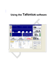
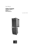
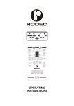
Frontpanel with controls
10
11 12 13
RODEC
1
20
2
21
22
3
23
24
4
25
5
26
6
7
8
27
28
29
9
X
30
Y
14
15 16 17 18
19
1)
Input select switch
This selector is used to select the input signal: MICRO, PHONO, LINE A or LINE B.
2)
Input level potentiometer
With this control the input level of each input channel can be set.
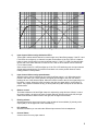
3)
Equalizer controls
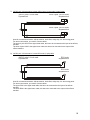
These controls regulate Treble, Middle and Bass levels.
7
+14
+12
LOW MAX
MID MAX
HIGH MAX
LOW MIN
MID MIN
HIGH MIN
+10
+8
+6
+4
+2
+0
-2
d
B
r
-4
-6
-8
-10
-12
-14
-16
-18
-20
-22
-24
20
50
100
200
500
1k
2k
5k
10k
20k
Hz
4)
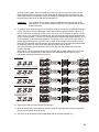
Input channel effects assign indication LED’s
These LED’s indicate which channel is routed trough one of the effects outputs. If the FX-1 and
FX-2 LED’s do not light up, no channel is routed via the effects. If the FX-1 LED of a channel
lights up green, that channel is routed via effects output 1. If the FX-1 LED of a channel lights
up red, one of the other channels is routed via FX-1 and no other channel can be routed via
FX-1 at that moment.
Same counts for the FX-2 LED that lights up. If the FX-1 LED is blinking red, the input channel
effects assign potentiometer (5) must be turned back to its center position because it was
initially placed in a fault position.
5)
Input channel effects assign potentiometer
With this control, the input signal can be routed via effects output 1 or 2. When the knob is
placed in the center (12 o’clock) position, the signal goes straight to the main mix without
passing via one of the effects-outputs. When the knob is turned to the left, the signal will go via
the effects 1 output. When the knob is turned to the right, the signal will go via the effects 2
output. The proportion between the dry (no effect) and wet (100% effect) can be set with the
potentiometer.
6)
Balance control
The balance between Left and Right channel is adjusted by using this knob. When it is set to
the center position, the gain is the same for both channels. When turned to the left, the right
channel will decrease. When turned to the right, the left signal will decrease.
7)
Routing selector
With this selector the signal can be lead: to the left side of the crossfader (X), directly to the
output (MIX) or to the right side of the crossfader (Y).
8)
PFL switches
With these switches you can select the different input sources for the headphones.
9)
Channel faders
Volume control for every input channel.
8
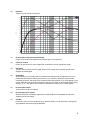
10)
Equalizer
Triple tone control for DJ microphone.
+15
LOW MAX
MID MAX
HIGH MAX
LOW MIN
MID MIN
HIGH MIN
+12.5
+10
+7.5
+5
+2.5
+0
-2.5
-5
d
B
r
-7.5
-10
-12.5
-15
-17.5
-20
-22.5
-25
-27.5
-30
20
50
100
200
500
1k
2k
5k
10k
20k
Hz
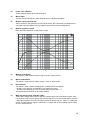
11)
DJ microphone input level potentiometer
Control for accurate level-adjustment of different types of microphones.
12)
Talk-over control
Control for the amount of music suppression controlled by the DJ microphone signal.
13)
VU meters
The two meters indicate the PFL signal. When no PFL-switch (8) is pressed, the VU-meter
displays the mixed signal.
14)
Crossfader
With this fader you can easily fade over between the channels with routing-selector (7) on Xposition and the channels with routing-selector (7) on Y-position. When the knob is turned
completely to the left, the signal of the channels with routing selector (7) on X will appear on the
output. When the knob is turned completely to the right, the signal of the channels with Routing
selector (7) on Y will appear on the output. In between there will be a mix of both signals.
15)
DJ microphone fader
Volume control for DJ microphone
16)
DJ microphone PFL switch
With this switch the microphone signal can be made audible in the headphones and made
visible on the left VU-meters.
17)
Pan Mic
Panoramic control for DJ microphone input. With this button you can position the microphone
signal between the left and right loudspeaker.
9
18)
Power "ON" indicators
These indicators light up when the power is on.
19)
Master fader
Volume controls final output of mixer towards slave or integrated amplifiers.
20)
Monitor output potentiometer
Volume control for the signal level for the monitor output, this output does not contain the DJmic signal to avoid feedback of the microphone-signal via the monitor loudspeakers.
21)
Monitor equalizer controls
Bass and treble adjustment for the monitor output.
+20
+18
+16
LOW MAX
HIGH MAX
LOW MIN
HIGH MIN
+14
+12
+10
+8
+6
+4
+2
d
B
r
-0
-2
-4
-6
-8
-10
-12
-14
-16
-18
-20
20
50
100
200
500
1k
2k
5k
10k
20k
Hz
22)
Monitor mode Switch
This switch is used to set the monitor output in mono or stereo mode.
23)
Master mode Switch
This switch is used to set the master output in mono or stereo mode.
24)
Record Select
This switch is used to make recordings with or without the DJ microphone.
+ DJ MIC: in this position you add the DJ mic signal to the music.
- DJ MIC: in this position you only record the signal from channel 1 - 5.
This switch has no influence on the master outputs.
25)
Main mix effects assign indication LED’s
These LED’s indicate if the main mix signal is routed through one of the effects outputs. If the
FX-1 and FX-2 LED’s do not light up, the main mix signal is not routed via the effects. If the FX1 LED lights up green, the main mix signal is routed via effects output 1. If the FX-1 LED lights
up red, an input channel’s signal is routed via FX-1 output and no other channel can be routed
via FX-1 at that moment.
10
Same counts for the FX-2 LED that lights up. If the FX-1 LED is blinking red, the main mix
effects assign potentiometer (26) must be turned back to its center position because it was
initially placed in a fault position.
26)
Main mix effects assign potentiometer
With this control, the main mix signal can be routed through effects output 1 or 2. When the
knob is placed in the center (12 o’clock) position, the signal goes straight to the main mix
without passing through one of the effects-outputs. When the knob is turned to the left, the
signal will go through the effects 1 output. When the knob is turned to the right, the signal will
go through the effects 2 output. The proportion between the dry (no effect) and wet (100%
effect) can be set with the potentiometer.
27)
Headphones-select potentiometer
With this potentiometer, the signal for the headphones output can be selected. When turned
completely to the left, the signal selected with the channel PFL-switches (8) appears on the
headphones. When turned completely to the right, the mix-signal appears on the headphones.
In between it results in a mix of the PFL-signal and the mix-signal.
28)
Headphones volume control
The volume of the headphones can be adjusted with this knob.
WARNING!
29)
Phones output
Output for high level headphones monitoring. With the PFL switches (8) and the headphonesselect potentiometer (27), the connected audio sources or the main-mix can be made audible
without manipulating the output signal (Headphones 32-600Ω).
ATTENTION!
30)
The sound and intensity volume of the headphones amplifier can be very
strong and, if not used properly, or if used in too close proximity, can cause
permanent or temporary damage to one’s hearing, perhaps even deafness.
Please use with caution and common sense!
Always turn headphones volume to “0” (fully counter clockwise) BEFORE
putting the headphones on your or somebody else her/his ears! Then
slowly raise the volume by turning the volume knob in clockwise direction.
Cross fader curve potentiometer
This potentiometer is used to set the sharpness of the cross fader. When the potentiometer is
turned completely to the left, the cross fader (14) will react as a normal cross fader. The
volumes of the channels with routing-selector (7) on Y-position will rise from 0 to maximum
when the shaft of the cross fader is moved from the left to the middle. The same counts for the
volumes of the channels with routing-selector (7) on X-position, but then from the right side to
the middle.
11
When the curve potentiometer is turned to the right, the cross fader will react very fast, with the
volumes of the channels with routing-selector (7) on Y-position rising from 0 to maximum when
the shaft of the cross fader is moved from the left to a few fractions from the left. The same
counts for the volumes of the channels with routing-selector (7) on X-position, but then from the
right side to a few fractions from the right side.
12
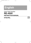
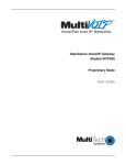
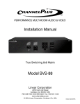
Backpanel with connectors
A
B
C
D
E
F
G
PS
E
H
I
J
Professional
Audio
Equipment
Made in
Belgium
K
WARNING
RODEC
DISCONNECT
POWERCORD
BEFORE OPENING
www.rodec.com
L
A)
M
N O P
Q R
S
Power switch
Controls the supply of AC power to the set. A single push turns on the mixing panel, a second
push turns it off.
Attention!
By turning off this switch, the mixing panel is in stand-by mode. At that moment
the mixing panel will still consume electricity from the mains net. The power
cord has to be unplugged from the power inlet to shut down all power.
B)
Power inlet
Universal mains power inlet.
C)
DJ microphone input
Balanced microphone input with a sensitivity of 4.2mV, with XLR-JACK combination connector.
D)
Effects IN/OUT
Input and output to connect effect equipment to the microphone channel. If there is no plug in
the JACK connector, the microphone channel works normally, if there is a plug inserted in the
JACK, the internal link is interrupted. The sensitivity of this IN/OUT connection is 775mV.
E)
Ground-terminal
Terminal to connect the ground wire of the vinyl turntable.
F)
Micro input
Balanced microphone input. To obtain good signal quality, you have to use a microphone with
balanced output. The use of a microphone without balanced output is also possible.
G)
PHONO input
Phono input with a sensitivity of 5.2mV and built in RIAA correction.
13
+20
+18
+16
+14
+12
+10
+8
+6
+4
+2
d
B
r
-0
-2
-4
-6
-8
-10
-12
-14
-16
-18
-20
20
50
100
200
500
1k
2k
5k
10k
20k
Hz
H)
Effects IN/OUT 1
In- and output to connect effect equipment to the music signal. The signal that runs through this
connector is controlled by the input channel effects assign potentiometer (5) or main mix effects
assign potentiometer (26). Internally linked when JACK is not inserted. Sensitivity 775mV.
I)
Effects IN/OUT 2
In- and output to connect effect equipment to the music signal. The signal that will run through
this connector is controlled by the input channel effects assign potentiometer (5) or main mix
effects assign potentiometer (26). Internally linked when JACK is not inserted. Sensitivity
775mV.
J)
Second headphones connector
Signal identical as headphones-output on the frontpanel (29). The specifications are the same
as the headphones output on the frontpanel.
K)
Asymmetrical master output
Asymmetrical output to connect a power-amplifier. The output level can be manipulated with
master fader (19) from 0 to maximum (0.775V).
L)
Symmetrical monitor output
Additional output up to 1.55V controlled by monitorpotentiometer (20). The DJ-microphone
signal does not appear on this output.
M)
Symmetrical master output
Symmetrical output to connect a power-amplifier or loudspeaker-processor. The output level
can be manipulated with master fader (19) from 0 to maximum (1.55V).
N)
Digital recording output
Output to connect to a S/P DIF input of a MD-recorder, CD-recorder, HD-recorder or DATrecorder to make recordings. This output can be switched with or without recording the DJ
14
microphone signal (24). Both signals (left and right) go through one connector. (Only provided
on channels 1 and 5)
O)
USB input/output
Optional USB connector to play music from PC or HD-player and simultaneously record the
main mix signal with a PC or HD-recorder. All 4 signals (reproduction left and right and
recording left and right) go through one connector. (Only possible on channels 1 and 5)
P)
Digital line input B
Digital S/P DIF input, to connect different equipment such as a CD player, MD player, DVD
player, MP3-player, HD-player or digital tuner. Both signals (left and right) go through one
connector. (Only provided on channels 1 and 5)
Q)
Analogue line input A
Analogue asymmetrical input with a sensitivity of 500mV, to connect different equipment such
as a CD player, MD player, DVD player, MP3-player, HD-player, analogue - or digital tuner,
cassette player or video player.
R)
Analogue recording output
Output to connect analogue recording device or (HIFI) video recorders to make recordings. This
output can be switched with or without recording the DJ microphone signal (24). (Only provided
on channels 2, 3 and 4)
S)
Analogue line input B
Analogue asymmetrical input with a sensitivity of 500mV, to connect different equipment such
as a CD player, MD player, DVD player, MP3-player, HD-player, analogue - or digital tuner,
cassette player or video player. (Only provided on channels 2, 3 and 4)
Please use signal cables shorter than 1 meter for the inputs and the outputs.
15
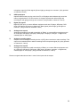
Cable configurations
a) Different audio connectors
Sleeve
Sleeve Ring Tip
Tip
JACK 3 pole 1/4 inch male
RCA (Cinch) male
Tip
Sleeve
Pin 4
Pin 3 Pin 2
Pin 1
USB A male
JACK 2 pole 1/4 inch male
Pin 2
Pin 2
Pin 1
USB B male
Pin 1
XLR 3 pole female
Pin 4
Pin 3
Pin 3
Pin 1
PHOENIX 4 pole female
Pin 2
XLR 3 pole male
Pin 3
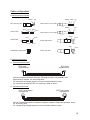
b) Different audio cables
1) Asymmetrical RCA cable:
RCA male
Asymmetrical
RCA male
Asymmetrical
Used for connections between: CD-player, MD-player/recorder, Vinyl turntable, DVDplayer/recorder, amplifier, etc. and mixing panel.
For connections of analogue signals, you need 2 of these cables for stereo
For connections of digital S/P DIF, you need only 1 cable for stereo
2) Symmetrical XLR cable:
XLR 3 pole female
Symmetrical
2
1
3
XLR 3 pole male
Symmetrical
1
2
3
Used for connections between: microphone, amplifier, equalizer, loudspeaker-processor, limiter,
etc. and mixing panel.
For connections of analogue signals, you need 2 of these cables for stereo
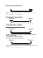
16
3) Symmetrical XLR female to JACK 3pole male cable:
XLR 3 pole female
Symmetrical
2
JACK 3 pole 1/4 inch male
Symmetrical
1
3
Used for connections between: microphone, amplifier, loudspeaker-processor, etc. and mixing
panel.
For stereo connections, you need 2 of these cables
4) Asymmetrical JACK 2 pole male to RCA male cable:
JACK 2 pole 1/4 inch male
Asymmetrical
RCA male
Asymmetrical
Used for connections between: electronic musical instrument, synthesizer, sampler, effectsmachine, amplifier, recorder, etc. and mixing panel.
For stereo connections, you need 2 of these cables
5) Symmetrical XLR female to asymmetrical RCA male cable:
XLR 3 pole female
Symmetrical
2
RCA male
Asymmetrical
1
3
Used for connections between: professional CD-player, professional MD-player, sampler, effectsmachine, etc. and mixing panel.
For stereo connections, you need 2 of these cables
6) Asymmetrical RCA male to symmetrical XLR male cable:
RCA male
Asymmetrical
XLR 3 pole male
Symmetrical
1
2
3
Used for connections between: professional recorder, sampler, effects-machine, amplifier, etc. and
mixing panel.
For stereo connections, you need 2 of these cables
17
7) JACK 3 pole 1/4 inch male to 2 times JACK 2 pole 1/4 inch male (Y-split) cable:
JACK 3 pole 1/4 inch male
Symmetrical
JACK 2 pole 1/4 inch male
Asymmetrical
JACK 2 pole 1/4 inch male
Asymmetrical
Used for connections between: effects-machine, audio-filter, delay-loop, etc. and mixing panel.
For stereo connections, you need 2 of these cables.
The upper 2 pole JACK is the signal send cable, this has to be connected to the input of the effectsmachine.
The lower 2 pole JACK is the signal return cable, this has to be connected to the output of the
effects-machine.
8) JACK 3 pole 1/4 inch male to 2 times RCA male (Y-split) cable:
JACK 3 pole 1/4 inch male
Symmetrical
RCA male
Asymmetrical
RCA male
Asymmetrical
Used for connections between: effects-machine, audio-filter, delay-loop, etc. and mixing panel.
For stereo connections, you need 2 of these cables
The upper RCA is the signal send cable, this has to be connected to the input of the effectsmachine.
The lower RCA is the signal return cable, this has to be connected to the output of the effectsmachine.
18
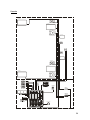
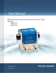
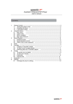
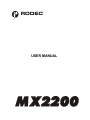
Operating instructions
For correct operation of the mixing panel, please follow the instructions below.
1) Before connecting anything to the mixing panel, be sure all equipment is turned off. Then
connect the different audio sources, amplifiers, effects-units, headphones, etc.. Next step is to
turn on the audio sources and effects-units.
When all these units are in ready state, you can switch on the power switch (A) of the mixing
panel. The power indicators (18) will light up.
After 5 seconds, you can turn on the loudspeaker processors and amplifiers.
PHONO
TURNTABLE
PHONO
TURNTABLE
DJ
MICROPHONE
SYNTHESIZER
SUB MIXER
REVERB
PROCESSOR
S
SS
IO
SS
SE
EE
ESS
SS
SSIO
IO
ION
NN
N// //
A
AU
UX
X IN
IN
AA
UU
XX
ININ
IN
1
ININ
INP
PP
PU
UU
UT
TT
T1
11
II IIN
NP
PU
UT
T2
2
NN
PP
UU
TT
22
PHO
PHONO
NO1 1
PHO
PHONO
NO1 1
L LEVEL
EVEL
L LEVEL
EVEL
STRAI
STRAIGHT
GHT
STRAI
STRAIGHT
GHT
REVER
REVERSE
SE
REVER
REVERSE
SE
RO
ROUT
UTININGG
RO
ROUT
UTININGG
LINE
LINE1 1
LINE
LINE1 1
MA
MAX X
MA
MAX X
MM
ICIC3 3
LINE
LINE3 3
LINE
LINE3 3
0 0dBdB
0 0dBdB
LEVEL
LEVEL
LEVEL
LEVEL
L LEVEL
EVEL
L LEVEL
EVEL
00
00
MA
MAX X
MA
MAX X
00
00
00
00
MM
AX
AX
MM
AX
AX
VU
VU
VU
VU
SELEC
SELECT T
SELEC
SELECT T
EQ
EQUALIZER
UALIZER
EQ
EQUALIZER
UALIZER
EEQQHIG
HIGHH
EEQQHIG
HIGHH
++
++
---
00
00
++
++
---
++
++
PPFL
FL
PPFL
FL
MM
IDID
MM
IDID
00
00
MM
AAX X
MM
AAX X
PF
PFL M
LM
IXIX
PF
PFL M
LM
IXIX
++
++
00
00
MM
ON
ONOO
MM
ON
ONOO
MM
OD
ODEE
MM
OD
ODEE
--LO
LOWW
LO
LOWW
MM
IDID
MM
IDID
HHIGH
IGH
HHIGH
IGH
WET
WET
WET
WET
FX
FX
- I-NINSSERT
ERT
FX
FX
- I-NINSSERT
ERT
FX
FX
- IN
- INSERT
SERT
FX
FX
- IN
- INSERT
SERT
LL
LL
RROU
OUTING
TING
RROU
OUTING
TING
00
00
MM
AX
AX
MM
AX
AX
EQ
EQUA
UALIZER
LIZER
EQ
EQUA
UALIZER
LIZER
---
HIHIGH
GH
HIHIGH
GH
MM
AAX X
MM
AAX X
MM
ASTER
ASTER
MM
ASTER
ASTER
22
22
L LEVEL
EVEL
L LEVEL
EVEL
CH
CH1 1
CH
CH1 1
CH
CH2 2
CH
CH2 2
00 00
00 00
--LOLOWW
LOLOWW
00
00
C
CC
CH
HH
HA
AA
AN
NN
NN
NN
NE
EE
EL
LL
L2
22
2
++ ++
++ ++
00
00
---
EEQQLO
LOWW
EEQQLO
LOWW
MM
ASTER
ASTER
MM
ASTER
ASTER
11
11
SE
SELECT
LECT
SE
SELECT
LECT
LILI
NNEE2 2
LILI
NNEE2 2
MM
IXIXL/CH
L/CH1 1 MM
IXIXR/CH
R/CH2 2
MM
IXIXL/CH
L/CH1 1 MM
IXIXR/CH
R/CH2 2
+5
+5
+5
+5
+3
+3
+3
+3
+ +1 1
+ +1 1
0dB
0dB
0dB
0dB
-1-1
-1-1
-3-3
-3-3
-5-5
-5-5
-10
-10
-10
-10
-20
-20
-20
-20
PPOWE
OWERR
PPOWE
OWERR
C
AN
CC
CH
HH
HAN
AN
ANN
NN
NE
EE
EL
LL
L1
11
1
INP
INPUT
UT
INP
INPUT
UT
SSELECT
ELECT
SSELECT
ELECT
EFFECTS MACHINE
O
TP
TS
OO
OU
UU
UTP
TP
TPU
UU
UTS
TS
TS
PPHO
HONO
NO2 2
PPHO
HONO
NO2 2
SELEC
SELECT T
SELEC
SELECT T
00
00
C
HA
EL
3
3
CC
CHA
HA
HAN
NN
NN
NN
NMEL
EL
EL
33
M
ICIC3 3
RR
RR
LL
LL
RR
RR
BALAN
BALANCE
CE
BALAN
BALANCE
CE
BA
BALANC
LANCEE
BA
BALANC
LANCEE
PFL
PFL
PFL
PFL
CCH1-2
H1-2
CCH1-2
H1-2
DDRY
RY
DDRY
RY
F FX-IN
X-INSER
SERT M
TM
IXIX
F FX-IN
X-INSER
SERT M
TM
IXIX
CH
CH1 1 MIX
MIX CH
CH2 2
CH
CH1 1 MIX
MIX CH
CH2 2
CU
CUT T
CU
CUT T
CU
CUT T
CU
CUT T
SAMPLER
PF
PFL C
L CH1
H1- CH2
- CH2SE
SELECT
LECT
PF
PFL C
L CH1
H1- CH2
- CH2SE
SELECT
LECT
RODEC
CH
CH1 1
CH
CH1 1
fi l te rt ec h nol og y
CH
CH2 2
CH
CH2 2
in s i d e
RODEC
RE
NO
NORM
RM
AL
AL
NO
NORM
RM
AL
AL
NO
NORM
RM
AL
AL
NO
NORM
RM
AL
AL
RREVERSE
EVERSE
RREVERSE
EVERSE
L
R
REVERS
REVERSEE
REVERS
REVERSEE
L
L
R
R
L
R
L
R
PS
E
L
R
L
R
Professional
Audio
Equipment
Made in
Belgium
WARNING
RODEC
DISCONNECT
POWERCORD
BEFORE OPENING
www.rodec.com
HEADPHONES
L
R
L
L
R
R
L
R
L
R
RODEC
fi l te rt ec h nol og y
in s i d e
RE
MASS STORAGE
PLAYER
DVD-PLAYER
LOUDSPEAKER
PROCESSOR
EFFECTS MACHINE
ACTIVE BOOTH
MONITORS
DAB RECIEVER
PROFESSIONAL
DOUBLE CD PLAYER
PC BASED MUSIC
PLAYER/RECORDER
TO MAIN
AMPLIFIERS
2) Connect the headphones to the headphones JACK connector (29) or (J). Use headphones with
impedance between 32 and 600Ω.
ATTENTION!
Always turn headphones volume to “0” (fully counter clockwise) BEFORE
putting the headphones on your or somebody else her/his ears! Then slowly
raise the volume by turning the volume knob in clockwise direction.
3) Choose with the input select switch (1) the right audio-source.
4) Switch the PFL button (8) in position ON to listen at the desired source. Turn the phones select
button (27) completely to the left and turn the phones volume potentiometer (28) to the desired
position to get the stereo signal on the headphones and the two left VU-meters. The PFL circuit
19
works as a sum-system, there is a possibility to listen to more sources at the same time. All
these operations have no influence on the output signal! Adjust with the level control (2) the
input signal until the red indicators of the level meters (13) will light up occasionally. Adjust if
necessary the quality of the sound with the equalizer (3).
LOOK OUT:
The equalizer at each input is used to manipulate the sound of each of the
input sources. To correct the acoustic of the room it is probably best to use an
external equalizer.
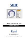
5) To send the input signal through one of the effects outputs, first check if the desired effects bus
is free. This can be done by checking the input channel effects assign indication LED’s (4). If
the FX-1 LED does not light up, the FX-1 bus is free. If the FX-2 LED does not light up, the FX2 bus is free. If one of the LED’s is blinking red, the input channel effects assign potentiometer
(5) is in a wrong position. Then first turn the input channel effects assign potentiometer to its 12
o’ clock position, so the LED will stop blinking. To select the FX-1 bus, turn the input channel
effects assign potentiometer to the left, first, no effect will be audible, but the influence of the
effect will increase when the potentiometer is turned further to the left. When the potentiometer
is completely to the left, 100% of the signal will be influenced by the effect.
The same procedure can be followed to select FX-2, but then the potentiometer has to be
turned to the right.
When the FX-1 bus is selected, the according LED will light up green, same for the FX-2 bus.
On the other input channels and on the main mix, the according LED will light up red, to
indicate the according effects-bus is occupied.
NO EFFECT SELECTED
NO SIGNAL
NO SIGNAL
RODEC
RODEC
f il t e r t e c h n o l o g y
i nsi de
RE
EFFECT SELECT POTENTIOMETER 1 ON WRONG POSITION
f il t e r t e c h n o l o g y
in s i d e
f il t e r t e c h n o l o g y
in s i d e
f il t e r t e c h n o l o g y
in s i d e
RE
L
L
R
R
NO SIGNAL
NO SIGNAL
RODEC
RODEC
f il t e r t e c h n o l o g y
i nsi de
RE
RE
BLINKING RED
L
L
R
R
SIGNAL OF CHANNEL 1
EFFECT 1 SELECTED ON CHANNEL 1
NO SIGNAL
RODEC
RODEC
f il t e r t e c h n o l o g y
i nsi de
RE
GREEN
RED
RE
RED
FX 1 SELECTED ON CH 1 AND FX 2 SELECTED ON CH 3
L
L
R
R
SIGNAL OF CHANNEL 1
SIGNAL OF CHANNEL 2
RODEC
RODEC
f il t e r t e c h n o l o g y
i nsi de
RE
GREEN
RED
RED
RED
RED
FX 1 SELECTED ON CH 1 AND
CH 2 POTENTIOMETER ON WRONG POSITION
L
L
R
R
SIGNAL OF CHANNEL 1
f il t e r t e c h n o l o g y
in s i d e
RODEC
f il t e r t e c h n o l o g y
BLINKING RED
in s i d e
NO SIGNAL
RODEC
i nsi de
RE
GREEN
f il t e r t e c h n o l o g y
RE
GREEN
RE
RED
L
L
R
R
6) Open up the fader (9) of the chosen input channel
7) Slide up master fader (19) till desired volume is reached. Also open the monitor potentiometer
(20), to hear the music at the DJ-booth.
8) The music in the DJ-booth can be manipulated with the monitor equalizer (21).
20
9) Correct if necessary the balance with button (6), for monophonic sound on master output set
switch (23) in mono position. For monophonic sound on monitor output, set switch (22) in mono
position.
10) If you like to use the crossfader (14), you can route the channel to the left (X) side of the
crossfader by putting the routing switch (7) on CF-X position. Or to the right (Y) side of the
crossfader when you put the routing switch (7) on the CF-Y position. The response curve of the
cross fader (14) can be adjusted with the cross fader curve potentiometer (30).
11) To change the source, repeat point 3) to 6).
12) By turning the headphones select potentiometer (27) more clockwise, you will increase the
amount of the main mix signal in the headphones.
13) To add a microphone signal, connect the microphone to the MIC input (C). Turn the level
control (11) and the talk-over (12) to zero, slide up the MIC fader (15) to maximum and adjust
with the level button (11) the volume of the microphone. Adjust with the equalizer (10) the
sound of the microphone. To use the talk over, adjust the talk over button (12) (0= no decrease,
10= total decrease). With the pan MIC (17), the DJ microphone signal can be placed
somewhere between left and right. Eventually you can connect an external processor
(example: compressor or reverb) to the effects insert (D) of the microphone channel.
14) The mixed signal can be recorded, simply by connecting a recorder to the analogue (R) or
digital (N) record-connectors. Depending on the position of the record-select switch (24) you
can decide if the microphone signal is also recorded or not. The mixed signal can also be
recorded with a computer through the optional USB connector (O).
15) The main mix signal can also be lead to one of the effects insert outputs. This can be done in
the same way as leading the signal of an input channel to the effects insert outputs, follow the
instructions of point 5). The effects assign indication LED’s for the main mix are LED’s (25). The
effects assignation for the main mix can be done with the main mix effects assign potentiometer
(26).
16) When no PFL is selected with the PFL switches on the input channels (7), the mixed signal will
appear on the VU-meters. If you like to compare via the VU-meters the pre-fade signal with the
output signal, you can do this by switching all PFL switches off first. Then switch the PFL switch
of the input channel you wish to compare with the mixed signal, on an off. In that way, both
signal levels can be compared.
SUBSONIC FILTER
The master output and the monitor output have a subsonic filter to protect the bass loudspeakers from
DC and subsonic signals. This filter cannot be switched off. The filter gives a reduction of 25dB at 10Hz.
21
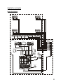
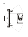
Application examples
Large discotheque
MAIN HALL
HORNLOADED LOUDSPEAKERS
HORNLOADED LOUDSPEAKERS
SUBWOOFERS
DJ-BOOTH
TECHNICAL ROOM
TABLETOP
CD PLAYER
LAPTOP
COMPUTER
EFFECTS MACHINE
RODEC
f i l ter tec hnol ogy
EFFECTS MACHINE
RODEC
i ns i de
f i l t e r t e c h n ol o g y
RE
RE
i ns i d e
POWER
AMPLIFIERS
TABLETOP
CD PLAYER
DJ
MICROPHONE
PHONO
TURNTABLE
PHONO
TURNTABLE
BOOTH
MONITOR
BOOTH
MONITOR
EXTERNAL
MULTICHANNEL
SOUNDCARD
BLUE-RAY-PLAYER
RODEC
POWER
AMPLIFIERS
LOUDSPEAKER
PROCESSOR
LJ HEADPHONES
LOUDSPEAKER
PROCESSOR
DJ HEADPHONES
X
Y
SUBWOOFER
22
Live electronic
PUBLIC AREA
FOH AREA
FOH MIXING PANEL
LINE ARRAY
LINE ARRAY
STAGE
LOUDSPEAKER
PROCESSOR
POWER
AMPLIFIERS
LOUDSPEAKER
PROCESSOR
POWER
AMPLIFIERS
LOUDSPEAKER
PROCESSOR
LOUDSPEAKER
PROCESSOR
LOUDSPEAKER
PROCESSOR
LOUDSPEAKER
PROCESSOR
POWER
AMPLIFIERS
POWER
AMPLIFIERS
POWER
AMPLIFIERS
POWER
AMPLIFIERS
LAPTOP
COMPUTER
LAPTOP
COMPUTER
EFFECTS MACHINE
SAMPLER
LOUDSPEAKER
PROCESSOR
LOUDSPEAKER
PROCESSOR
POWER
AMPLIFIERS
POWER
AMPLIFIERS
EFFECTS MACHINE
RODEC
RODEC
VOCAL
MICROPHONE
MONITOR MIXING DESK
MIDI KEYBOARD
EFFECTS MACHINE
RODEC
SYNTHESIZER
SOUND MODULE
RODEC
ACTIVE DI BOX
MONITOR
MONITOR
LOUDSPEAKER
PROCESSOR
DJ HEADPHONES
SUBBASS
SUBBASS
POWER
AMPLIFIERS
ACTIVE DI BOX
X
Y
23
Karaoke
PUBLIC AREA
STAGE
LOUDSPEAKER
LCD SCREEN
LCD SCREEN
SUBWOOFER
LCD SCREEN
STAGE MONITOR
VOCAL MICROPHONES
STAGE MONITOR
LCD SCREEN
LOUDSPEAKER
LCD SCREEN
LCD SCREEN
SUBWOOFER
DVD-PLAYER
DJ-BOOTH
EFFECTS MACHINE
LASER DISC-PLAYER
MC
MICROPHONE
RODEC
f i l te r t e c h n o l o g y
in s i de
RE
DVD-PLAYER
BLUE-RAY-PLAYER
ACTIVE BOOTH
MONITOR
CD PLAYER
POWER
AMPLIFIERS
LCD PREVIEW SCREEN
RODEC
LOUDSPEAKER
PROCESSOR
POWER
AMPLIFIERS
VIDEO MIXER
DJ HEADPHONES
X
Y
24
AMPLIFIERS WITH
BUILT IN PROCESSOR
TECHNICAL
ROOM
LINE ARRAY
CENTER FILL
LOUDSPEAKER
UHF ANTENNA
FLASH-CARD
PLAYER
FOH
PUBLIC AREA
MONITOR
LOUDSPEAKER
X
STAGE
Y
RODEC
WIRELESS TRANSMITTERS
WITH HEADSET MICROPHONES
DJ HEADPHONES
MONITOR
LOUDSPEAKER
EQUALIZER
ANTENNA COMBINER
WIRELESS
MICROPHONE
RECIEVERS
UHF ANTENNA
CENTER FILL
LOUDSPEAKER
LINE ARRAY
AMPLIFIERS WITH
BUILT IN PROCESSOR
TECHNICAL
ROOM
Theatre
25
Internet radio broadcast
PRESENTATOR AND
INTERVIEW BOOTH
HEADPHONES
HEADPHONES
HEADPHONES
RADIO
BROADCAST
MICROPHONE
RADIO
BROADCAST
MICROPHONE
RADIO
BROADCAST
MICROPHONE
HEADPHONES
AMPLIFIER
TECHNICAL-BOOTH
EFFECTS MACHINE
LCD-DISPLAY
PC BASED MUSIC
PLAYER/RECORDER
RODEC
PC BASED JINGLE
PLAYER
f i l te r t ec h n o l og y
INTERNET
SERVER
COMPUTER
i n s i de
RE
STUDIO
CD-PLAYER
PC-KEYBOARD
COMPRESSOR
TO THE INTERNET
RODEC
ACTIVE
MONITORS
ACTIVE
MONITORS
TECHNICIAN
HEADPHONES
X
Y
26
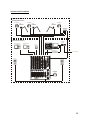
Options
1) USB I/O set MX00
Optional input/output kit to connect the mixing panel with a computer. The USB connector
contains 1 stereo input signal and 1 stereo record output signal. With this option music can be
played from a computer via USB. Simultaneous the mixed music can be recorded via the
computer. The option must be built in as follows: First pull off the fader knobs (9, 14, 15 & 19) at
the frontpanel. Then unscrew the aluminum fader cover plate (6 screws). Take of this aluminum
plate. Then unscrew the bottombox, 3 screws at the frontpanel, one screw at each side and 3
screws at the bottom.
Screw of the hole cover plate (at the backpanel) which covers the desired hole for the USB
option set. Place the USB option so that the 6 pole angled connector on the USB PCB fits in
the 6 pole angled connector on the input PCB. Screw the screw in the hole in the backpanel to
mount the USB option kit. Close the mixing panel again by replacing the bottombox (8 screws),
the aluminum fader cover plate (6 screws) and the fader knobs (8 pieces).
Connect the USB I/O set to a computer via a USB-cable. The computer will recognize the USB
I/O set. Select the USB I/O set as playback- and recording device in the sound and audio
configuration menu of the computer or audio-software.
The USB I/O set MX00 can be ordered at every authorized RODEC-dealer.
Order code: 94 001 0070
2) Digital optical input channel fader MX00 set
Users can upgrade their mixing panel with digital faders on the music input channels. The
digital faders replace the standard analogue faders. The option must be built in as follows: First
pull off the fader knobs (9, 14, 15 & 19) at the frontpanel. Then unscrew the aluminum fader
cover plate (6 screws). Take of this aluminum plate. Unscrew the channel fader, which you like
to replace (2 screws). Pull off the 4 pole flat cable at the input PCB. Place the 10 pole flatcable
(delivered together with the digital optical input channel fader set) on the 10 pole connector
(right below the PFL switch) on the input channel PCB. Connect the other side of the flatcable
to the digital optical input channel fader. Screw the fader to the frontpanel (2 screws), attention,
the 10 pole connector on the fader PCB must be placed at the side of the crossfader (14).
Replace the aluminum fader cover plate and fader knobs. The digital optical input channel fader
is ready to use.
The digital optical input channel fader MX00 set can be ordered at every authorized RODECdealer.
Order code: 94 001 0072
3) Digital optical crossfader MX00 set
The standard analogue crossfader can be upgraded by a digital optical crossfader. The option
must be built in as follows: First pull off the fader knobs (9, 14, 15 & 19) at the frontpanel. Then
unscrew the aluminum fader cover plate (6 screws). Take of this aluminum plate. Then unscrew
the bottombox, 3 screws at the frontpanel, one screw at each side and 3 screws at the bottom.
Unscrew the crossfader (2 screws). Pull off the 4-pole flatcable of the crossfader on the output
PCB. Place the 10 pole flatcable (delivered together with the digital optical crossfader set on
the 10 pole connector on the output PCB. Connect the other side of the flatcable to the digital
optical crossfader. Screw the digital optical crossfader to the frontpanel (2 screws), attention,
the 10 pole connector on the fader PCB must be placed at the opposite side of the output PCB.
Replace the bottombox (8 screws), the aluminum fader cover plate (6 screws) and fader knobs.
The digital optical cross fader is ready to use.
The digital optical cross fader MX00 set can be ordered at every authorized RODEC-dealer.
Order code: 94 001 0073
27
4) Standard knobs set MX00 series
The knobs of a MX00 series mixing panel can be ordered in a set. For a MX2200 you need 1 of
these sets to replace all the knobs.
The standard knobs set MX00 series can be ordered at every authorized RODEC-dealer.
Order code: 94 001 0074
5) Fader knobs BX/CX/MX MKIII/MX00 series
The fader knobs of a MX00 series mixing panel can be ordered in a set. For a MX2200 you
need 1 of these sets to replace all the fader knobs.
The fader knobs BX/CX/MX MKIII/MX00 series can be ordered at every authorized RODECdealer.
Order code: 94 001 0041
28
Specifications
0dBm = 0.775V RMS
Nominal analogue input levels:
- Line A asymmetrical (RCA): 500mV / 50kΩ
- Line B asymmetrical (RCA): 500mV / 50kΩ
- Phono asymmetrical (RCA gold plated): 5.2mV / 50kΩ
- Microphone (channel 1 – 5) symmetrical (XLR): 9.1mV / 3.6kΩ
- Microphone symmetrical (XLR or ¼” TRS JACK): 4.2mV / 1.8kΩ
- Effects return (1/4” TRS JACK): 775mV / 10kΩ
- Priority in (optional) (RCA): 500mV / 1.5kΩ
Nominal analogue output levels:
- Master asymmetrical (RCA): 775mV / 10kΩ
- Master symmetrical (XLR): 1.55V / 600Ω
- Monitor symmetrical (XLR): 1.55V / 600Ω
- Record asymmetrical (RCA): 500mV / 10kΩ
- Effects send asymmetrical (1/4” TRS JACK): 775mV / 10kΩ
- Headphones (1/4” TRS JACK):
- 8Ω: (1kHz – 1%THD) 417mW (1.8V) / 1.1W music power
- 32Ω: (1kHz – 1%THD) 1.0W (5.7V) / 1.7W music power
- 600Ω: (1kHz – 1%THD) 520mW (17.7V) / 0.6W music power
Digital input:
- Line B (RCA): S/P DIF IEC 958 type II 32kHz – 192kHz
- USB (optional): 32kHz - 48kHz 16bit
Digital output:
- Record (RCA): S/P DIF IEC 958 type II 44.1kHz
- USB (optional): 11.025kHz - 48kHz 16bit
Signal headroom: 20.0dB @ 1kHz / THD < 0.05%
Crosstalk:
-
Left to right of an input channel: >60dB @ 1kHz
Channel to channel: >86dB @ 1kHz
Frequency response: +/- 0.25 dB from 20Hz to 20kHz
Subsonic filter: -25dB at 10Hz
Dynamic range: 103dB
Signal to noise ratio: 90dB
Total harmonic distortion: < 0.006%
29
Music equalizer:
- Low: +10dB / -21dB at 100Hz
- Mid: +10dB / -21dB at 1kHz
- High: +10dB / -21dB at 10kHz
Microphone equalizer:
- Low: +12dB / -12dB at 100Hz
- Mid: +12dB / -12dB at 1kHz
- High: +12dB / -12dB at 10kHz
Monitor output equalizer: - Low: +12dB / -12dB at 100Hz
- High: +12dB / -12dB at 10kHz
Power supply voltage: 90VAC – 264VAC
Power supply frequency: 47Hz – 63Hz
Power consumption: 45W (On), 68W (Full load), 6W (Stand by)
Operating temperature: 0°C (32°F) – 40°C (104°F)
Operating humidity: 5% - 90% (no condensation)
Mechanical specifications:
Frontpanel dimensions (W x D): 320.0mm (12.6”) x 355.0mm (14.0“) (8HE)
Bottombox dim. (W x D x H): 312.0mm (12.3“) x 343.0mm (13.5“) x 110.0mm (4.3“)
Panel cut out dimensions (W x D): 316.0mm (12.4“) x 347.0mm (13.7“)
Packed box dimensions (W x D x H): 410.0mm (16.2“) x 414.0mm (16.3“) x 207.0mm
(8.1“)
Weight: 5.54kg (12.21lbs)
Packed weight: 6.70kg (14.77lbs)
30
Explanatory words list
Amplitude: The amplitude is the size, the strength of a vibration. This can be a mechanical vibration,
for example a snare of a guitar, or the, from that arisen, sound wave or from any other cyclical varying
appearance in time. Because any waveform always varies in size, the value of the wave will also vary.
The amplitude is the value from zero to the maximum hit out or strength of the wave.
Analogue signal: (synonym: analog signal) An analogue signal is any time continuous signal. The
amplitude of the signal varies continiously in function of time. Human-ears can only hear analogue
signals (sounds). Digital sounds must always be converted to analogue signals to make them audible.
Asymmetrical (synonym: unbalanced): An unbalanced line is a transmission line, usually coaxial cable,
whose conductors have unequal impedances with respect to ground.
Balance: Balance means the amount of signal from each channel reproduced in a stereo audio
recording. Typically, a balance control will have 0dB of gain in the center position for both channels,
and attenuate one channel as the control is turned, leaving the other channel at 0 dB.
Binary: The binary numeral system, or base-2 number system, is a numeral system that represents
numeric values using two symbols, usually 0 and 1.
Bit: A bit is a binary digit, taking a value of either 0 or 1.
CD: Abbreviation for Compact Disc. It is an optical disc used to store digital data, originally developed
for storing digital audio. The CD, available on the market since late 1982, remains the standard
playback medium for commercial audio recordings to the present day. An audio CD consists of one or
more stereo tracks stored using 16-bit PCM coding at a sampling rate of 44.1 kHz. Standard CDs have
a diameter of 120 mm and can hold approximately 80 minutes of audio.
Crossfader (synonyms: CF, X-fader or XF): A crossfader essentially functions like two faders
connected side-by-side, but in opposite directions. It allows a DJ to fade one source out while fading
another source in at the same time with one knob.
DAB: Digital Audio Broadcasting (DAB), is a technology for broadcasting of audio using digital radio
transmission.
DAT: Digital Audio Tape is a signal recording and playback medium. The audio data is stored on a
magnetic tape. It uses 48, 44.1 or 32 kHz sampling rate and 16 bits quantization.
dB: Abbreviation for decibel (1/10 of a Bel). dB is a logarithmic unit of measurement that expresses the
size of a physical quantity relative to a reference level. Its logarithmic nature allows very large or very
small ratios to be represented by a convenient number. The decibel is commonly used in acoustics to
quantify sound levels relative to some 0dB reference. The reference level is typically set at the
threshold of human perception. A reason for using the decibel is that the ear is capable of detecting a
very large range of sound pressures.
Digital signal: A digital signal is one that uses discrete values (electrical voltages), rather than a
continuous spectrum of values (ie, as in an analogue signal).
DJ: Abbreviation for Disc Jockey. A DJ is a person who plays pre-recorded (not live) music, either or
not in front of an audience.
Dry signal: Opposite of “Wet signal”. This is the signal as it is, without added deformation, effects,
tone-manipulation, etc.
31
DVD: Also known as "Digital Versatile Disc" and "Digital Video Disc", is a popular optical disc storage
media format used for data storage, mainly movies. Most DVDs are of the same dimensions as
compact discs, but store more than 6 times the data.
Equalizer: Equalization (or equalisation, EQ) is the process of changing the frequency envelope of a
sound. The audio band is subdivided in 2, 3 or more subbands, the volume of each of these bands can
be amplified or attenuated with an equalizer.
Fader: Is a linear potentiometer. Faders are mostly used to increase or decrease in the level of an
audio signal. By moving the knob, the volume increases or decreases. A fader can be either analogue,
a movement of the knob will result in a change of the resistance or digital, the movement of the knob
generates a binary code, this code is used to change the volume.
Flash card: A memory card or flash memory card is a solid-state (no moving parts) electronic flash
memory data storage device, which can be electrically erased and reprogrammed.
Frequency: Frequency is the measurement of the number of occurrences of a repeated event per unit
of time. The result is measured in hertz (Hz). A baby can hear tones with frequencies from 20Hz to
20000 Hz (20kHz), but these frequencies become more difficult to hear as people age. When a tone
with a frequency of 20Hz is played by a loudspeaker, the loudspeaker will reciprocate 20 times per
second.
FX: Abbreviation for effects-unit. An effects unit is used to manipulate the sound of music or voice.
Some effect units transform the sound completely, others just color the sound picture in a minor way.
HD: Abbreviation of hard disc. It is a non-volatile storage device, which stores digitally encoded data on
rapidly rotating platters with magnetic surfaces.
Headphones: Are a pair of tiny loudspeakers that are hold close to humans ears. DJ’s use types with
pads that go around the ears, usually very large and very comfortable.
Hz: Abbreviation of Hertz, named after the German physicist Heinrich Rudolf Hertz. The hertz is the unit
of frequency. Its base unit is cycles per second. Each musical note corresponds to a particular
frequency which can be measured in hertz.
I/O: Abbreviation for input / output
Insert: An insert is an access point built into the mixing console, allowing the user to add external line
level devices into the signal flow.
JACK: It is cylindrical in shape, typically with three contacts (TRS), although sometimes with two (a TS
connector) or four (a TRRS connector). TRS stands for Tip, Ring and Sleeve. In audio-systems, it is
used to connect headphones, microphones, effects-units, electrical musical instruments, etc.
kHz: Abbreviation of kilo Hertz, is 1000 Hertz (see Hz)
LED: Abbreviation of Light emitting diode. Is an electronic component that emits light when an electrical
current flows through it.
Loudspeaker: A loudspeaker, speaker, or speaker system is an electromechanical transducer that
converts an electrical signal into sound. The term loudspeaker can refer to individual devices (or
drivers), and complete systems consisting of an enclosure incorporating one or more drivers and
additional electronics.
32
Line: Line level is a term used to denote the strength of an audio signal used to transmit analogue
sound information between audio components such as CD-players, DVD-players, input signals of audio
amplifiers, mixing consoles, etc. Sometimes also called AUX (auxiliary) signals.
MD: Abbreviation of Mini Disc. It is a rewriteable magneto-optical disc-based data storage device for
storage of up to 80 minutes of digitalized audio.
Micro: Abbreviation of microphone. (synonym: mike or mic) Is an acoustic to electric transducer that
converts sound into an electrical signal.
Mono: Abbreviation of monaural. Typically there is only one microphone, one loudspeaker, or, in the
case of headphones or multiple loudspeakers, they are fed from a common signal path, and in the case
of multiple microphones, mixed into a single signal path at some stage.
MP3: Abbreviation of MPEG-1 Audio Layer 3. This is an audio encoding format. It uses a lossy
compression algorithm that is designed to greatly reduce the amount of data required to represent the
audio recording, yet still sound like a faithful reproduction of the original uncompressed audio to most
listeners.
Mute: If an audio signal is muted, it is turned off or it’s volume is turned to a lower level.
Pan: Abbreviation of panoramic or panning. Panning is the spread of a monaural signal in a stereo or
multi-channel sound field. A typical pan control is constant power. At one extreme, the sound appears
in only one channel. In the middle, the sound is decreased in that channel by 3 dB, and the other
channel is brought up to the same level, so that the overall sound power level is always constant.
PCM: Abbreviation of Pulse Code Modulation is a digital representation of an analogue signal where
the magnitude of the signal is sampled regularly at uniform intervals, then quantized to a series of
symbols in a digital (usually binary) code.
PFL: Abbreviation of Pre Fader Listening. (synonym: cue) This is a function in an audio mixing panel to
allow the user of the mixing panel to listen to the music (mostly via headphones) before the audience
hears the music.
Phono: Abbreviation of phonograph. Also called turntable, record player or pick-up. Is a device to play
music from vinyl records.
Potentiometer: Is an electrical device, which has a user-adjustable resistance. Usually, this is a threeterminal resistor with a sliding contact in the center (the wiper). By moving the wiper, the resistance
changes. These changes are used to to change the characteristics of the audio signal.
Quantized: Quantization is the process of approximating a continuous range of values (or a very large
set of possible discrete values) by a relatively small set of discrete symbols or integer values.
RCA (cinch, tulip): Is a type of electrical connector that is commonly used in the audio/video market.
The name "RCA" derives from the Radio Corporation of America, which introduced the design by the
early 1940s to allow phonograph players to be connected to amplifiers. Now these connectors are used
for connections between amplifiers, CD-players, phono-turntables, etc. For analogue audio you need 2
of these connectors for a stereo signal. For digital audio (S/P DIF) only one connector is needed for a
stereo signal. The connectors are colour coded: Left or mono -> White, Right -> Red, S/P DIF ->
Orange.
Rec (recording): Sound recording is the electrical inscription of sound waves, usually used for the voice
or for music. The two main classes of sound recording technology are analogue recording and digital
recording.
33
RIAA: RIAA equalization is a specification for the correct playback of vinyl records, established by the
Recording Industry Association of America (RIAA). The purpose of the equalization is to permit greater
playback times, improve sound quality, and to limit the physical extremes that would otherwise arise
from recording analogue records without such equalization. A record is cut with the low frequencies
reduced and the high frequencies boosted, and on playback the opposite occurs. The result is a flat
frequency response.
Sample: In music, sampling is the act of taking a portion, or sample, of one sound recording and
reusing it as an instrument or element of a new recording. This is typically done with a sampler, which
can be a piece of hardware or a computer program.
In signal processing, sampling is the reduction of a continuous signal to a discrete signal. Sampling
picks out samples from a continious signal at a certain frequency. When it is necessary to capture audio
covering the entire 20-20kHz range, such as when recording music, audio waveforms are typically
sampled at 44.1 kHz (CD) or 48 kHz (professional audio).
Sound: Sound can be perceived by the sense of hearing. By sound, we commonly mean the vibrations
that travel through air and are audible to people. Humans and many animals use their ears to hear
sound, but loud sounds and low-frequency sounds can be perceived as vibrations by other parts of the
body via the sense of touch. Sound propagates as waves of alternating pressure, causing local regions
of compression and rarefaction.
S/P DIF: Abbreviation for Sony / Philips digital interconnect format. It specifies a protocol for carrying
digital audio signals between devices.
Stereo: Stereophonic sound is the reproduction of sound, using two independent audio channels.
Stereophonic sound attempts to create an illusion of location for various instruments within the original
recording.
Subsonic signal: This is an audio signal with frequency below 20Hz. This signal is not audible, it only
creates air movement that can be felt.
SUM signal: This signal is the proportional summation (mix) of all input signals. Also called main mix
signal.
Symmetrical (synonym: balanced): A balanced line or balanced signal pair is a transmission line
consisting of two conductors of the same type, and equal impedance to ground and other circuits.
Balanced lines are operated with differential signals, one of which is the inverse of the other. Balanced
lines reduce the amount of noise per distance, allowing a longer cable run to be practical. This is
because electromagnetic interference will affect both signals the same way. Similarities between the
two signals are automatically removed at the end of the transmission path when one signal is
subtracted from the other.
Talk-over (synonym: voice-over, ducker): It is an effect where the level of one signal is reduced by the
presence of another signal, through the use of side chain compression. A typical application is to
automatically lower the level of the musical background when a talk-over starts, and to automatically
bring the level up again when the talk-over stops.
THD: Abbreviation of Total Harmonic Distortion. When a signal passes through a non-linear device,
additional content is added at the harmonics of the original frequencies. THD is a measurement of the
extent of that distortion.
USB: Abbreviation for Universal Serial Bus. It is a serial bus standard to transport data between (mostly
computer related) devices.
34
Volume: The amount of audio level. If the volume increases, the audio level will increase, which results
in a louder sound.
VU: Abbreviation of volume units. A VU meter is often included in audio equipment to display a signal
level. It is intentionally a "slow" measurement, averaging out peaks and troughs of short duration to
reflect the perceived loudness of the material.
Wave: A wave is a mode of energy transfer from one place to another, often with little or no permanent
displacement of the particles of the medium. Mechanical waves require a medium to transverse the
distance, electromagnetic waves can travel through a vacuum.
Wet signal: Opposite of “Dry signal”. This is the signal inclusive added deformation, effects, tonemanipulation, etc.
XLR: This is a connector invented by Cannon. Originally the "Cannon X" series, subsequent versions
added a Latch ("Cannon XL") and then a Rubber compound surrounding the contacts, which led to the
abbreviation XLR. The most common is the 3-pin XLR3, used almost universally as a symmetrical
audio connector for high quality microphones and connections between equipment.
35
36
Manufactured by:
Transtel – Sabima NV
Duboisstraat 50
B-2060 Antwerp
Belgium
Tel: 00 32 (0)3 237 36 07
Fax: 00 32 (0)3 216 97 62
e-mail: [email protected]
URL: http://www.rodec.com
37