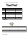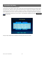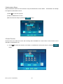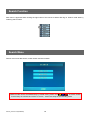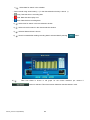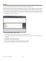
1
STAND-ALONE DVR EL-4000 SERIES USER MANUAL 2008.08.22 INDEX System Introduction---------------------------------------------------1 Warning------------------------------------------------------------------------2 EL-4000 Series System Components--------------------------------4 EL-4000 System Front / Back Panel----------------------------------5 Remote Control Function----------------------------------------------14 EL-4000 System Connection------------------------------------------15 EL-4000Series Specification------------------------------------------16 General Information--------------------------------------------------18 Precaution for Setup------------------------------------------------------19 Initial Surveillance Screen-----------------------------------------------22 EL-4000 Setup Configuration--------------------------------------25 User Log IN-------------------------------------------------------------------26 Setup Configuration-------------------------------------------------------27 System Setup------------------------------------------------------------28 Menu-----------------------------------------------------------------------------29 System Setup-----------------------------------------------------------------30 Information--------------------------------------------------------------30 Time Setup---------------------------------------------------------------32 Disk Manager------------------------------------------------------------37 User Setup----------------------------------------------------------------42 Factory Default----------------------------------------------------------44 Log Off---------------------------------------------------------------------45 System Shutdown------------------------------------------------------45 Device Setup-------------------------------------------------------------------46 Camera---------------------------------------------------------------------46 Audio------------------------------------------------------------------------51 Alarm------------------------------------------------------------------------52 Screen Display Setup--------------------------------------------------56 Buzzer Setup--------------------------------------------------------------58 Recording Setup---------------------------------------------------------------59 Setup-------------------------------------------------------------------------59 Schedule Setup-----------------------------------------------------------62 Network Setup-------------------------------------------------------------------63 Network Setup-------------------------------------------------------------63 E-mail Notification Setup-----------------------------------------------65 Manual_Version 3.00(20080822) i Web Server Setup---------------------------------------------------------66 DDNS Setup-----------------------------------------------------------------67 Event Notification Setup------------------------------------------------68 Bendwidth Limit------------------------------------------------------------69 Event Information Search-----------------------------------------------------70 Sensor Log-------------------------------------------------------------------70 Camera Loss Log-----------------------------------------------------------71 System Log-------------------------------------------------------------------71 PTZ Function-----------------------------------------------------------------72 Digital PTZ---------------------------------------------------------------------------73 Freeze Function-------------------------------------------------------------------74 Dynamic PTZ-----------------------------------------------------------------------74 Search Function-------------------------------------------------------------76 Search Structure------------------------------------------------------------------77 Search Function-------------------------------------------------------------------78 Search Menu------------------------------------------------------------------------78 Calendar Search-------------------------------------------------------------------79 Operation---------------------------------------------------------------------79 Search Setup----------------------------------------------------------------79 Motion Search----------------------------------------------------------------------80 Operation---------------------------------------------------------------------80 Search Setup----------------------------------------------------------------81 Event Search-----------------------------------------------------------------------82 Operation---------------------------------------------------------------------82 Search Setup----------------------------------------------------------------83 Search--------------------------------------------------------------------------------85 Search Menu------------------------------------------------------------------------86 Screen Division in Search Mode---------------------------------------------87 Backup Function------------------------------------------------------------88 Backup Preparation--------------------------------------------------------------89 Backup Function------------------------------------------------------------------89 Backup Process------------------------------------------------------------90 Preview Player--------------------------------------------------------------92 Replay of Backup File----------------------------------------------------93 Simple Viewer-----------------------------------------------------------------------93 Manual_Version 3.00(20080822) ii Assembly & Installation Guide---------------------------------------96 HDD Connection---------------------------------------------------------------97 EL-4000 Relay Characteristies--------------------------------------------98 Remote Surveillance Function----------------------------------------99 Remote Surveillance Program-------------------------------------------100 Program Installation------------------------------------------------100 RS(Remote Surveillance) Environment Setup----------------------102 RS program ON-------------------------------------------------------102 Site Registration------------------------------------------------------103 Group Registration--------------------------------------------------104 User Registration-----------------------------------------------------105 System Setup----------------------------------------------------------106 Record--------------------------------------------------------------------107 RS(Remote Surveillance)---------------------------------------------------108 Site Connection-------------------------------------------------------108 Remote Surveillance Function-----------------------------------109 Remote PTZ Function-----------------------------------------------112 System Control--------------------------------------------------------113 Search Window--------------------------------------------------------123 Backup--------------------------------------------------------------------127 Finish and Reset-------------------------------------------------------130 Web Surveillance Program---------------------------------------------131 Web Surveillance Program--------------------------------------------------132 Static IP Connection--------------------------------------------------132 Dynamic IP Connection----------------------------------------------132 Security Warning------------------------------------------------------133 Connection and Termination------------------------------------------------134 Surveillance Function---------------------------------------------------------135 Surveillance Screen-------------------------------------------------135 Sensor and Control Icon-------------------------------------------135 Camera Selection----------------------------------------------------135 Screen Division-------------------------------------------------------136 PTZ Function---------------------------------------------------------------------136 Search Function----------------------------------------------------------------136 Surveillance Screen Search------------------------------------------------137 Manual_Version 3.00(20080822) iii APPENDIX (DDNS)-------------------------------------------------------138 DDNS Registration-----------------------------------------------------------139 Client Connection------------------------------------------------------------140 Manual_Version 3.00(20080822) iv System Introduction Manual_Version 3.00(20080822) 1 Warning WARNING: To prevent a risk of fire of electric shock, do not expose this product to rain or moisture. • This installation should be made by a qualified service person and should conform to all local codes. • This is a Class A product. In a domestic environment this product may cause radio interference in which case the user may be required to take adequate measures. z This system operates time using charge battery in the system. Use this system after time setup in the beginning. Battery can be discharged completely if battery is not used for a long time unplugged or moving the system during system operation. If system is reused after complete battery discharge by plugging power supply, time will be the initial time setup status. The data in HDD that is recorded with the date that is later than current time may be deleted in order to sync time. Therefore, separate HDD and approve power supply and then do time setup and install HDD again and use the system again. z Enquire to the supplier or dealers if you have any question or defective goods for repair. z Please read user manual carefully before starting the system. z Do not open the system as it is, because the inside of the system has very sensitive substances to the environment. z Put the power cord safely and do not touch power cord with wet hands. z Do not use loose plug outlet and damaged power cable. z Do not touch exposed plug outlet to prevent electrical shock. If necessary, wear electricity-proof gloves. z Exit power properly on the program before turning off the system with peripheral devices. z Be cautious not to drop conductive objects in the ventilation area of power supply device and the inside of the system. z Do not disassemble or modify system. z Do not put heavy objects on top of the system. z Do not give shock to the system while on the move. z Turn off the power switch right away if there is smoke or smell in the system. Consult with the supplier for the advice of expertise. Manual_Version 3.00(20080822) 2 EL-4000 Series System Components 25P Connector Model Name Mouse EL-4004L 1 EL-4008M Video Output Cable 25P Connector I/O Input Connector N/A 1 N/A 1 N/A 1 N/A EL-4016M 1 1 (16 ch ) 1 N/A EL-4016H 1 1 (16 ch ) N/A 2 (16 pin) (Loop Out Cable) ► Common feature: User manual, SW CD, Remote Control & power cable. ► Specification per model name, refer model specification table Manual_Version 3.00(20080822) 3 EL- 4000 System Front / Back Panel Front (Common) 1 2 3 ① Power Button 1. ② CD-R/W[DVD-R/W] Button & MOUSE function in the front panel 2. Button & MOUSE function in the front side Manual_Version 3.00(20080822) 4 ③ USB2.0 HOST PORT (1) LED group Power ON/OFF & Standby Mode Recording Alarm Occurrence Network Connection Status HDD Recording Status Power LED: Red, Green (2 Color ON/OFF/BLINK) Red: Stand-by, Red (Flickering): Booting status, Dark Green: Operation status HDD LED: Yellow (ON/OFF) ON: Operation status is OK after successfully access HDD OFF: Recognition is not fulfilled and can’t record Alarm LED: Yellow (BLINK) BLINK: When one or more sensor operate Network LED: Yellow (ON/OFF) ON: Cable connection is OK, OFF: LAN cable is not connected or problem occurs in LAN environment. Recording LED: Yellow (ON/OFF) LED ON: Recording status, OFF: STOP recording Manual_Version 3.00(20080822) 5 (2) Enter & Arrow button 1) Enter Button: Selection This button is used for the menu item, division screen selection etc Division screen: When pressing button, the channel is selected. If double clicking the channel, it becomes full screen and becomes previous division Mode status if double click again. MENU activation: Select item on the cursor.’ Motion area setup: Select area on the cursor 2) ▲►▼◄ Arrow Button: Movement This button is used for the menu item movement & Pan/Tile/Zoom control in PTZ mode. Division mode: Channel movement in the screen PTZ mode: PTZ or dynamic PTZ control in the screen 3) MENU Button: Enter to Menu Mode System LOG ON Status: Display system setup menu in the screen System LOG OFF Status: Display LOG ON screen It is the same with the right button of the mouse for the above status Motion Area Setup: Selection cancellation for the area of cursor (Enter button is used for the selection) 4) PTZ Button: PTZ Mode Activation/ Cancellation. It does not any function if PTZ module does not exist in LIVE mode. Menu->Device->Camera>Dynamic PTZ System Log Off status: LOG ON screen display JOY STICK icon is displayed in the right bottom of the PTZ module setup channel indicating PTZ activation. Arrow button is the Pan and Tilt function. Zoom in/out function are also activated. 5) SEARCH Button: Enter to Search mode System Log Off status: LOG ON screen display System Log On status: Search screen display 6) SEQ Button: Division page rotation activation / cancellation Current division screen pages are displayed in order based on page rotation time setup. Page rotation time setup : Refer system setup in DVR Menu->Device->Display->Sequence->Main Monitor Dwell Time Manual_Version 3.00(20080822) 6 If channel is not selected in the main monitor, it is not included in the sequence. Menu->Device->Display->Sequence->Main Monitor There is no change in case of 16 channels and 16 divisions mode. 7) MODE Button: Screen division mode change Division mode from 1 to Maximum division are displayed in order e.g. 16channel 16 division. The same when pressing the wheel button of the mouse Screen division mode is changed based on the sequence setup mode in the current division screen 8) JOG / Jog / Single 4 division 6 division 8 division 9 division 10 division 13 division 16 division SHUTTLE: Shuttle. JOG/SHUTTLE function is used in replay mode and do not have function in other mode. JOG: Device for Frame search. One frame is replayed to the forward direction per each movement of JOG in case of the clockwise direction. Previous key frame is replayed per each movement of JOG in case of backward replay mode. Key frame is the frame that has complete image in MPEG. JOG/SHUTTLE: Device for Ultra speed search. Forward and backward replay and control speed ± 1, ± 2, ± 4, ± 16, ± 32, ± 64, ± 128, ± 256 is possible. It operates by forward x1 speed by default. Audio is activated only for ±1 mode and key frame is replayed. Manual_Version 3.00(20080822) 7 9) ESC Button: Cancellation Menu mode is disappeared. Return to the previous menu. (The same function with return button in menu) 10) ◄ / Zoom In Button Replay mode: Backward x1 times replay speed PTZ Mode: Used for the screen Zoom in 11) ► / Zoom Out Button Replay mode: Forward x1 times replay speed PTZ Mode: Used for the Screen Zoom out 12) Button: Mute. Stop replay temporarily. This function is used for replay mode only and no function except for replay mode. 13) Q Button: Emergency Recording Start/ Cancellation Emergency recording records all channel by full frame recording (CIF) regardless of recording setup. It records all channel continuously by maximum frame regardless of recording setup such as resolution, sensor, motion etc. In case of this situation, current time is displayed by blue and dark green from yellow color display. Resolution is CIF to maintain maximum frame. If selecting this function key, normal recording mode is returns. It is very useful in case of emergency situation. Manual_Version 3.00(20080822) 8 (3) USB 2.0 Port: External USB device connection. Connect by Max.480Mbps with external USB device 1) Connectable device: USB stick memory, USB CD/RW and USB HDD for backup devices. 2) 10Mbps (USB1.1) is possible to connect depending on the device of connection. 3) Be careful not to put metal pieces etc near the port connection area because power (5V) output exists in the port. (4) IR receiver IR (Infra Red) remote control receiver 1) Receiver that receives signal for the system control and setup through remote control Back Panel [Model: EL-4016H] 1. Port in the back side ⓞ Video Input [1~16] ① VGA Video Output ② Composite Video Output ③ S-Video Output ④ 2-WAY AUDIO Input ⑤ NTSC/PAL Selection ⑥ USB2.0 HOST 2 PORTS ⑦ LAN Port ⑧ RS-232C Port ⑨ ⑩ Loop Video Output [1-16] ⑪ Power [110~220V AC] ⑫ Spot Video Output ⑬ Audio Output ⑭ Audio Input[1~4] ⑮ Main Power Switch ⑧ RS-232C: Joystick etc ⑨ RS-485 : PAN/TILT Control Manual_Version 3.00(20080822) 9 Sensor/Relay/RS-485 Connector 2. JOY Stick Connector Pin Arrangement Pin No. Signal Name Pin No. Signal Name 1 RS-422 TX- 6 NC 2 RS-422 TX+ 7 NC 3 RS-422 RX+ 8 NC 4 RS-422 RX- 9 NC 5 GND Manual_Version 3.00(20080822) 10 3. SENSOR/RELAY/RS-485 Input/Output Connector Pin Configuration Pin No. Signal Name Pin No. Signal Name 1 Relay 1-A 17 Sensor 1 2 Relay 1-COM 18 Sensor 2 3 Relay 1-B 19 Sensor 3 4 Relay 2-A 20 Sensor 4 5 Relay 2-COM 21 Sensor 5 6 Relay 2-B 22 Sensor 6 7 Relay 3-A 23 Sensor 7 8 Relay 3-COM 24 Sensor 8 9 Relay 3-B 25 Sensor 9 10 Relay 4-A 26 Sensor 10 11 Relay 4-COM 27 Sensor 11 12 Relay 4-B 28 Sensor 12 13 GND 29 Sensor 13 14 GND 30 Sensor 14 15 RS-485+ 31 Sensor 15 16 RS-485- 32 Sensor 16 Manual_Version 3.00(20080822) 11 Back Panel [Model: EL-4016M, EL-4008M & EL-4004L] 1. Port in the back side : EL-4016M ⓞ Video Input ① VGA Video Output ② S-Video Output ③ Composite Video Output ④ 2-WAY AUDIO Input ⑤ NTSC/PAL Selection ⑥ USB2.0 HOST 2 PORTS ⑦ LAN Port ⑧ RS-232C Port ⑨ ⑩ Loop Video Output ⑪ Power[110~220V AC] ⑫ Audio Output ⑬ Spot Video Output ⑭ Audio Input [1~4] ⑮ Main Power Switch 2. [1~8] EL-4008M Video Input (1~4) EL-4004L Sensor/Relay/RS-485 Connector Port in the back side : EL-4008M , EL-4004L ⓞ Video input[1~8] EL-4008L/M ① VGA Video output ② S-video output ③ Composite Video output ④ 2-WAY AUDIO input ⑤ NTSC / PAL selection ⑥ USB2.0 HOST 2 PORTS ⑦ LAN port ⑧ RS-232C PORTS ⑨ ⑩ Loop Video output ⑪ Power[110~220V AC] ⑫ Audio output ⑬ Spot video out ⑭ Audio input [1~4] ⑮ Main Power Switch Manual_Version 3.00(20080822) Video input[1~4] EL-4004L 12 Sensor/Relay/RS-485 Connector 3. SENSOR/RELAY/RS-485 Input/Output Connector Pin Configuration 13 12 11 10 9 8 7 6 5 4 3 2 1 4 24 23 22 21 20 19 18 17 16 15 14 Pin No. Signal Name Pin No. Signal Name 1 Sensor 13 14 Relay out (NO) 2 Sensor 12 15 Relay out com 3 Sensor 11 16 NC 4 Sensor 10 17 COM 5 Sensor 9 18 RS 485 (+) 6 Sensor 8 19 RS 485 (-) 7 Sensor 7 20 Com 8 Sensor 6 21 Com 9 Sensor 5 22 Com 10 Sensor 4 23 Sensor 16 11 Sensor 3 24 Sensor 15 12 Sensor 2 25 Sensor 14 13 Sensor 1 z NC : Not connected 4. JOY Stick Connector Pin Configuration Pin No. Signal Name Pin No. Signal Name 1 RS-422 TX- 6 NC 2 RS-422 TX+ 7 NC 3 RS-422 RX+ 8 NC 4 RS-422 RX- 9 NC 5 GND Manual_Version 3.00(20080822) 13 Remote Control Function Power button Input Control ID Control ID Setting Set Control ID UP Select function Left Down Right Zoom In Back MENU Zoom Out Run Sequence PTZ Pause Play forward Screen Mode Search Record Play backward Play fast forward Play fast backward Play one frame backward Play one frame forward * Warning : Remote control ID must be set to communicate with DVR system. Remote control ID setup: ① Press for ID button 3 seconds approximately (red LED flickers) ② Input 2 digit ID number for DVR. (Menu->SYSTEM->Information->Control ID) ③ Record setup by pressing ID SET button. Manual_Version 3.00(20080822) 14 EL- 4000 System Connection 1. Model: EL-4016L/M/H 2.EL-4008L/M & EL-4004L Manual_Version 3.00(20080822) 15 EL- 4000 Series Specification Model Video Audio Camera input EL-4004L EL-4008M EL-4016<M>/H 4 8 16 Output 1 BNC, S-Video, VGA(OPTION)/1 SPOT/LOOP OUT Audio input 4 RCA /1 2-WAY AUDIO Output 1 RCA Sensor In (NO, NC)/Alarm out 4/1 8/1 Operating System 16/4 Embedded Linux OS Speed[NTSC/PAL] 120/100 fps 240/200 fps Resolution (Pixel) Display 16/1 480/400 fps 704 X 480(NTSC), 704 X 576(PAL) Split screen 1,4,SEQ 1,4,6,8,9,SEQ 1,4,6,8,9,10,13,16,SEQ Zoom Digital x 2 others De-interlaced Video, Graphic OSD On/Off, HDD automatic Calculation and ETC Compression MPEG-4 SP Resolution (Pixel) 704x480, 704x240, 352x240 (NTSC) / 704x576, 704x288, 352x288(PAL) Picture quality High, middle, low Mode Continuous/Motion/Sensor/Sensor & Motion/Schedule NTSC Recording Total Speed PAL 30 fps (704x480) 60 fps(704x480) 120<60> fps(704x480) 60 fps (704x240) 120 fps(704x240) 240<120> fps(704x240) 120fps (352x240) 240 fps(352x240) 480<240>fps(352x240) 25 fps (704x576) 50fps (704x576) 100<50> fps(704x576) 50 fps (704x288) 100fps (704x288) 200<100> fps(704x288) 100fps (352x288) 200fps (352x288) 400<200> fps(352x288) Each NTSC Max30fps Max30 Max30<15> channel PAL 25 fps Max25 Max25<12> Water Marking Manual_Version 3.00(20080822) Own Algorithm 16 Playback Display 1,4,SEQ Search mode 1,4,6,8,9,SEQ 1,4,6,8,9,10,13,16,SEQ Date, time, event (motion, alarm), camera Zoom Digital x 2 Normal, REW & FF [recorded speed ±4, ±16, ±32], Frame to frame, Pause Jog : ± 1 Frame Speed Suttle : recorded speed ± 1, ± 2, ± 4, ± 16, ± 32, ± 64, ± 128, ± 256). Device Internal / External HDD from USB2.0 Interface Device Backing up file MPEG4 compression or AVI Format format Network Interface Network Protocol TCP/IP, SMTP, HTTP, DHCP, PPPOE(ADSL) Application Windows XP(PC Client system) Web Browser Backup Ethernet, USB Port Internet Explorer 5.0 Higher ( DVRs control or viewing ) Internal Device DVD or CD-RW(option) External device USB HDD, Memory Stick(USB2.0), Network Each Area Control / channel Motion Detection Sensitivity : 3 steps for each channel Area : Selectable motion detection area for each camera individually Control Alarm Pre Hold time Max 180 fps Hold time 5 ~ 240 SEC Event log Alarm, Motion, video Loss, power loss, power on/off, record on/off IR/MOUSE/JOG YES Pan/Tilt YES Joystick Interface Others Others YES(OPTION) HDD Supports Max. 4 HDD Storage Temp/Humidity -20~ 0’C/20~80% RH Oper. Temp/Humidity -5~40’C/20~80% RH Power Source AC100~240V 50/60Hz Dimension/Weight Manual_Version 3.00(20080822) 420mm(W)*70mm(H)*390mm(D)/8Kg 17 General Information Manual_Version 3.00(20080822) 18 Precaution for Setup 1. The method of changing SETUP parameters. Hot function key of the System in the front side, remote control, mouse and virtual keyboard can be used to change DVR system menu, setting etc. Most of items (items that user want to change) can be changed by mouse, button. Regarding text input that needs to be added or changed in the setting, virtual keyboard is used for text insertion. In case of keyboard, put the cursor to the item (the item that user wants to change) and press Enter / Front Enter. Then virtual keyboard is appeared for the text insertion. Virtual keyboard is disappeared by pressing Enter / Front ESC button after input Saving of newly changed setup is completed automatically when main menu is closed. Manual_Version 3.00(20080822) 19 ♣ Maximum number of word in the input box. Input Location Component Max. Number Of Word DVR Title SYSTEM -> Information 47 Time Server SYSTEM -> Time Setup -> Time Sync 40 User ID SYSTEM -> USER ACCOUNT 19 Password SYSTEM -> USER ACCOUNT 9 Camera Title DEVICE - > Camera 47 XDSL ID NETWORK -> IP Setup 39 XDSL PWD NETWORK -> IP Setup 19 IP NETWORK -> IP Setup 15 MASK NETWORK -> IP Setup 15 GW NETWORK -> IP Setup 15 DNS NETWORK -> IP Setup 15 MAC NETWORK -> IP Setup 19 Receiver NETWORK -> E-MAIL Notification 49 Sender NETWORK -> E-MAIL Notification 49 SMTP Server NETWORK -> E-MAIL Notification 49 Account NETWORK -> E-MAIL Notification->Authentification 49 Password NETWORK -> E-MAIL Notification->Authentification 49 WEB Port NETWORK -> WEB SERVER SETUP 6 DDNS ID NETWORK ->DDNS 49 DDNS PSWD NETWORK -> DDNS 19 Target Address NETWORK ->Event Notification 49 Network Port NETWORK 6 Manual_Version 3.00(20080822) 20 2. Setup saving and menu movement à OK button: Saving the selected setup mode until now. à Cancel button: Go out of the GUI menu à Back button: Go back to the previous menu from current GUI à 3. System rebooting after setup. Some of setup mode is not possible to operate during system operation after saving setup. These items are only available after rebooting the system again. Our system is made to reboot automatically if these items setup are recorded. 4.HDD data automatic deletion when time/date change Our system operates time using embedded charge battery. Setup time newly In the beginning for the initial use. Charge battery can be discharged if the system is on the move during operation or disuse for a long time with unplugged. If discharged completely and use again by plugging power supply then initial time setting is the initial time as factory default. . The data in HDD that is recorded with the date that is later than current time may be deleted in order to sync time. Therefore, separate HDD and approve power supply and then do time setup and install HDD again and use the system again. 5. The initial operation status after POWER ON This system checks system status such as camera/HDD etc after power authorization. If there is no problem after checking, recording is processed by factory default (Full frame recording by CIF mode for the all channel). If recording mode is processed alright, red color wheel is appeared in the LIVE channel screen. Manual_Version 3.00(20080822) 21 Initial Surveillance Screen Screen Introduction When DVR system starts, real-time video surveillance screen is shown after logo screen. 3 2 4 5 6 7 1 8 10 11 9 1.Screen Introduction 1) 1 2) 2 Basic surveillance screen Surveillance camera name Camera name can be reviewed in the directory as below. Menu -> Device -> Camera -> Camera Title 3) 3 Recording status: It shows continuously when recording status is continuous mode. When recording status is motion detection and alarm/sensor mode, it shows when event occurs. 4) 4 Audio recording status: It shows when audio recording is set. It appears in the upper right side in the channel screen if camera is setup with audio in the audio setup. (Menu -> Device -> Audio) Manual_Version 3.00(20080822) 22 5) 5 This is acronym of Frames per Second for the camera. Go to Menu -> Device -> Display -> FPS and select. 6) 6 Dynamic PTZ: This appears when PTZ module is set. Go to Menu -> Device ->Camera -> Dynamic PTZ and register. 7) 7 Motion & Alarm Sensor z Yellow: Motion detection occurs in the continuous or alarm sensor mode. z Blue: No motion detection occurs in the motion recording mode. z Red: Motion detection is occurs in the motion recording mode. z Yellow: Alarm occurs in the continuous or alarm sensor mode. z Blue: No Alarm occurs in the alarm mode. z Red: Alarm occurs in the alarm sensor mode. 8) 8 Screen division selection button. This button appears when mouse is located to the bottom of surveillance screen. Division screen mode is changed by pressing the middle wheel button of the mouse Screen rotates based on sequence order in the current screen mode. 1 screen 4 division screen 6division screen 8 division screen 9 division screen 10division screen 13division creen 16 division screen ; Reference: Screen division icon is different per each model based on each system. 4channel system(up to 4channel) / 8channel system (up to 9channel) / 16channel system (up to 16channel) 9) 9 Current time (Mode: year-month-date/month-date-year/date-month-year) Blue and dark green color shows emergency recording status and yellow color for the normal recording status. Emergency recording is started when Q button in the front panel or remote control. Manual_Version 3.00(20080822) 23 10) 10It shows system temperature status and run based on the temperature (temperature that user set) à Blue: It shows that system temperature is alright à Red: It shows that system temperature is higher than system temperature setup. (Cooling fan is run to lower system temperature.) It operates based on Temperature Indicator setup. (Menu -> Device -> Alarm -> System -> Temperature Indicator) 11) 11 HDD status: It runs based on the setup status that user set. à Blue: It shows that HDD has enough space for recording. à Yellow: It shows that HDD is very near to the setup value by user. à Red: It shows that current HDD is over than the setup value by user. Go to Menu -> Device -> Alarm ->System -> HDD Indicator and setup. 2.Screen Location Change Channel swapping function is in the division screen mode. When no.1 screen needs to be shown bigger than current mode, press the left button of mouse and drag to no.2 screen, then no.1 and no.2 screen locations swap. 2 1 1 2 After Swap Before Swap #Screen Zoom IN Double click the left button of mouse in the screen among multiple screens. The screen will be changed to the Full screen mode. The screen becomes full screen from division screen mode when pressing enter button twice very fast after moving the cursor to the channel by arrow button in the front panel or remote control. Previous division screen mode is back when pressing enter button twice very fast again. Manual_Version 3.00(20080822) 24 EL- 4000 Setup Configuration Manual_Version 3.00(20080822) 25 User Log IN Log In process must be completed in order to change system setup or to use system function. There are administrator who control system and normal users up to 1~9 users based on authorization. Normal user input user password to log-in after selecting user in the ID using scrawl button. However, normal users can be applied when administrator registers normal user in advance. √ Live screen can be shown and division mode control of live screen is possible without logging in. ; Note: Initial password of administrator is “1234” ; This initial password can be changed after log-in with initial password. Manual_Version 3.00(20080822) 26 Setup Configuration Manual_Version 3.00(20080822) 27 System Setup Manual_Version 3.00(20080822) 28 Menu Main menu is shown at the left bottom of the screen when pressing the right button of the mouse. Authorization for each item is applied to administrator and normal users have only permitted authority by administrator. 1)Menu System, device, record, network, event setup is possible and only administrator can do this. This item needs very careful control due to its status of system operation 2)Search Recorded data can be searched by various type such as calendar search/motion search/event search) 3) Backup Backup is possible to CD/DVD-RW and external USB backup device. 4) Digital PTZ Zoom In/Out and movement is possible for the surveillance screen. 5) Freeze Freeze function for the surveillance screen for the temporary period of time. 6) Dynamic Pan/Tilt Zoom In/Out/movement/focus control are possible for the surveillance screen when PTZ module is connected. Manual_Version 3.00(20080822) 29 System Setup There are specific function items such as information, time setup, disk manager, user account, factory default, log off, shut down in the system window. √ Information Information such as system name, remote control setup, language system version, video signal type can be obtained or changed in the system setup. 1 2 3 4 5 6 Manual_Version 3.00(20080822) 30 1 System Name System name: Virtual keyboard is appeared when selecting the left button of mouse in the system name input window and system name can be modified. It is possible to input maximum 48 characters but it only shows 18 characters when inputting system name. 2 System ID (Remote Control ID) Remote control ID is used when remote control ID is needed to change & setup. ID can be set between 0~99. Initial ID of the system is 0. This ID is to connect DVR system and remote control by one to one relation. 3 Auto Lock[Minute] If there is no operation during set time, the DVR will be automatically logged off. NOT USE : No use of this function Even though NOT USE is selected, the DVR will be also automatically logged off if there is no operation for one hour. Time set: 1 minute ~ 15 minutes 4 Language Selection Select system language and when factory default item is selected, English is selected. English, Korean, Japanese, Taiwan language can be selected. 5 Version Show version information of system operation program There are main version and sub version. The first 2 numbers are main version and the last 4 numbers are sub version. ex) 2.0.080101 : 2.0 Main version, 080101 Sub version 6 Signal Type Signal type is shown for TV Video standard based on the region it belongs and this signal type is changed by NTSC/PAL switch in the back panel. ; Note: When signal type is changed, it must be rebooted with system. Manual_Version 3.00(20080822) 31 Time Setup There are items for time setup, DST, holiday & time sync in the time setup window. 1.Time Setup Activate time setup item by selecting time setup tab of time setup main menu. Time and standard time zone in the system can be selected for the time setup. This time setup is used for record and real-time surveillance screen. 1 2 3 4 1) 1 Standard Time Zone: Korea is GMT+09. Change the time zone using the scrawl bar button in the display window. 2) 2 Date Display: Setup time display mode in the system. (YY-MM-DD/MM-DD-YY/DD-MM-YY) Change date display mode using scrawl bar button in the display window. ; Date display example ♦ YY-MM-DD: 0000year-00month-00date ♦ MM-DD-YY:00month-00date- 0000year ♦ DD-MM-YY: 00 date 00 month 0000 year 3) 3 Date: Change date for the system. Change date by using the scrawl bar Manual_Version 3.00(20080822) 32 button to change. 4) 4 Time: Change the time in the system. Use the scrawl bar button for each item display window to change. Only the standard time zone and date format can be changed when time sync is selected. If time and date is changed, error message appeared as below. Apply the time setup after completion of time setup by selecting button. ; In case of changing to the past time, data in the past is deleted. So, prepare the backup or other method to save the data ; It is highly recommended to boot the DVR and set time before HDD install when initially system sets in order to avoid data loss in case. Manual_Version 3.00(20080822) 33 2. DST (Daylight Saving Time) It is used on daylight saving time applied area. Check USE. Set Start and End time and date. When the DVR system time is in daylight saving time, the function will be automatically applied and letter D will be shown on the DVR system time of the below of main screen. Manual_Version 3.00(20080822) 34 3. Holiday Setup Selected holidays are applied to the holiday recording schedule in the recording schedule. Activate holiday setup item by selecting holiday tab in the time setup main menu. Holiday can be deleted or added. Holiday setup is applied to when schedule recording is applied and then it is recorded according to holiday schedule. 2 1 1)Add Holiday Max. 10 holidays can be addable. To do so, delete past holidays to add new holiday cause it has no automatic deletion function. z Select holiday date in the calendar 1 . à Select month using arrow button(◀, ▶) in the date selection window(◀ 2007/4 ▶). à Gray has no holiday registration. à Red is the current date user selected. à Blue is holiday registration date. z Add holiday by selecting button z Selected date is registered in the holiday list 2 . 2)Holiday modification z Select new date to register in the calendar 1 z Select date to modify in the holiday list 2 . Selected date is shown in white color. z Apply holiday modification by selecting Manual_Version 3.00(20080822) button. 35 3)Holiday Deletion z Select the date to delete in the list 2 . button. z Delete selected date by selecting z Save holiday environment setup by selecting OK button. 4.Time Sync Time Sync function is matching time between DVR system and Time Server automatically. Activate time sync item by selecting time sync tab in the time setup main menu. Automatic time sync can bring time information from the time and fix time automatically. If automatic time sync is set, only time format can be changed for the time setup. After connection to Time Server, it takes Max.10 seconds to apply Time Server time in DVR. Time Sync is not possible if connection to Time Server fails. ; Time server default value is time.nist.gov 1 2 3 1) 1 Check checkbox in front of automatic sync item à Automatic sync à No automatic sync 2) 2 Input time server IP 3) 3 Select the interval time for the time sync from the time server. Manual_Version 3.00(20080822) 36 Disk Manager Data recording and backup of the system is managed in disk manager. Disk type is defined using format button when HDD is added for the data recording. Format is used when CD/DVD-RW media is used for the backup. USB disk is deleted by using delete button when USB disk needs to be deleted after use. 1. HDD Disk Information Check 1 4 2 3 1) 1 Disc information is reviewed after selection. 2) 2 Total size, free space and information etc are displayed. z Embedded HDD z CD/DVD RW: \ ※ If media do not exist in RW device, total size is 0 ※ Format is available for MEDIA which can be reusable. (RW TITLE) Manual_Version 3.00(20080822) 37 z USB MEMORY: ※ If recording type is NTFS, Output will be by WINDOW FORMAT. 3) 3 Select if format is wanted. 4) 4 Removal button is generated if external USB MEMORY is selected. If click this removal item, removal message is appeared and if confirming removal, USB MEMORY is disappeared. After that, USB can be removed safely. 2.HDD Disk Format HDD, USB Memory, CD-RW, DVD-RW format is possible. NTFS format is not supported. Therefore, USB Memory, USB HDD are formatted by DOS (FAT) Max. 32G Bytes Format is processed as follows. ; Note Do not operate other work when format is processed. Remind that recorded data is permanently deleted from formatted HDD disk and can be retrievable again. 1) Select Format Manual_Version 3.00(20080822) button after checking HDD-1. 38 2) Recording is stopped during format process. Select 3) Recorded data is deleted. Select button if format is continued. button if format is continued. 4)Generate format type after processing HDD disk format Manual_Version 3.00(20080822) 39 5)If format is finished, available space is displayed in the HDD disk information window 1 6) After formatting, a message pops up and it asks “Format completed Reboot?” Please click NO if there is another HDD that is needed to be formatted and proceed format again. Please reboot the DVR system after formatting all HDDs Manual_Version 3.00(20080822) 40 3. Additional HDD 1)Additional new HDD disk must be processed after closing the system. 2)Turn off the power supply switch of the system 3)Setup as slave for the additional HDD disk ; Be careful when additional HDD disk is put to the previous system. Master and slave setup for the HDD must be very careful. 4)Connect additionally to the previous HDD disk connection cable. 5)Format is processed after searching for the new device when system is turned ON. 6)Registration for the new HDD disk 1 and check HDD capacity 2 ; If additional new HDD disk information is not displayed, please check the connection status again. Manual_Version 3.00(20080822) 41 User Setup User addition/deletion & ID/password can be changed. Authorization & covert function setup per user by setup button 1.Normal User Registration Only administration can register normal user. 1) 1 Select USER1 in the user selection window. 2) 2 Input user ID, password, password confirmation 3) 3 Setup user authorization 4)Save environment setup by selecting Manual_Version 3.00(20080822) OK button 42 2.Authorization Setup Setup Authorization status for the normal user. Only the selected item can be usable. Administrator can manage to change this authorization control. 1)Check for the user to permit 2) Setup available items for users 3)Save environment setup by selecting OK button. 3.Covert Function Covert function can make live screen and recording data unavailable for normal users. Covert function can be changed by administrator only. 1) Check the items that needs to be hidden to usersRecord environment setup by selecting button Manual_Version 3.00(20080822) 43 OK Factory Setup Be precautious. Factory default function may cause all environment setup by administrators to the initial factory setup mode. If factory default function is selected, system is closed. Press the power button in the front panel to reboot the system. 1) 1 Click 2) 2 Click button 3) Setup box is appeared. Yes: Factory default is done and reboot. No: Factory default is done and shutdown. Manual_Version 3.00(20080822) 44 Log Off Log off function returns to the previous status before log in. when system operation/setup values are changed, log in must be reactivated. It is automatically log off if user does not use mouse, keyboard and remote control for 5 minutes. System Shutdown System shutdown function makes system shut down very safely after stopping of the recording and operation for the system. It is OK to unplug AC after system shut down. In case of this, system is restarted when power button in the front panel is selected. Manual_Version 3.00(20080822) 45 Device Setup Device setup window manages and setup all devices used in the system. Device setup function control camera, audio, alarm and screen display. Camera Camera name, recording frame number, recording image resolution and PTZ function can be set. Brightness, contrast and color are controlled by color control button. 1.Camera Setup Camera name, recording frame number of each camera or all cameras and recording image resolution can be set. Also, it is possible to set full image display when event occurs for the selected setup camera. 1 2 3 4 5 6 7 8 9 Manual_Version 3.00(20080822) 46 1) 1 ) in the camera selection window Select camera ( Select OK when each camera needs to be setup individually. 2) 2 Activate menu by selecting setup tap 3) 3 Select if selected camera will be used for the recording and display utility. Check 4) 4 for use. (Remain unchecked when unused) Selection of Popup Use: This function display in the full screen mode for the selected camera by users when event (motion detection etc) occurs. ( : Use / : No Use) 4000 SERIES FRAME RATE TABLE Select recording image size per channel. Select among High (D1), Middle (2CIF) and Low (CIF). Category Max. Frame Number Resolution EL-4016H EL-4016M EL-4008M EL-4004L NTSC PAL CIF 480 400 2CIF 240 200 D1 120 100 CIF 240 200 2CIF 120 100 D1 60 50 CIF 120 100 2CIF 60 50 VGA 30 25 5) 5 Input camera name that is displayed during recording and display. 6) 6 Setup Resolution 7) 7 Change recording frame number by using scrawl bar 8) 8 Select recording resolution 9) 9 Display selected Frame Rate 10) Save environment setup by selecting OK button. Manual_Version 3.00(20080822) 47 button. 2. Dynamic PTZ Setup All kinds of PTZ camera can be connected to use. Dynamic PTZ function is usable by selectingPTZ device (PTZ module) and H/W address. 1) 2 Activate menu by selecting dynamic PTZ tap 2) 1 Select camera ( ) in the camera selection window à All cameras are selected if button is selected. If you press the button, the setting vakue will be applied to all à (Example: Select select by the right button of the mouse and setup each camera and and confirm OK.) 3) 3 Select the camera that is currently used by selecting PTZ device using scrawl bar button. PTZ LIST ORX-1000 UNITEC LG_LPT_A100L Samsung_SCC641 Sungin, Samsung_SSRX100A VICON, Fine CRR1600 PELCO-D PELCO-P KALATEL_KTD312 Manual_Version 3.00(20080822) 48 4) 4 5) 5 Select HW address for the same device of the PTZ setup using scrawl bar Setup specific features to connect PTZ device by selecting button button After input Baud rate, data bit, stop bit, parity bit value provided in the PTZ device user manual, save it by selecting OK button If not setup, default mode is applied that was registered by manufacturer. 6) 6 Save environment setup by selecting Manual_Version 3.00(20080822) 49 OK button. 3.Color Setup Setup the brightness, contrast and saturation for the camera signal per camera. Setup value is applied to the recording & display mode. 1)Start Color Control color button. 1 3 2 4 2) 1 Select camera for color control in the camera selection window. 3) 2 Select wanted color using brightness/contrast/saturation control bar 4) 3 Save environment setup by selecting 5) 4 Default Color value Manual_Version 3.00(20080822) 50 button control by selecting Audio This system has 4 audio input terminals and can be used by connecting to each video channel. 1) 1 Select camera for audio channel by using scrawl bar 2) 2 Select Not Use in case of no use for the audio channel 3)Save environment setup by selecting Manual_Version 3.00(20080822) button. OK 51 button Alarm This alarm function is used for the setup of event input/output that is available by connecting to the system. User can setup and use system alarm based on the sensor, motion and video loss event input. 1. Sensor Alarm Sensor alarm is setup by normal close, normal open and sensor input port can be used by setting video image, output relay terminal and operation time. 1) 2 Activate menu by selecting sensor tab 2) 1 Select sensor for setup in the sensor selection window. (A number of cameras can be selected with the right button of the mouse) : All cameras are selected if button is selected. : If yoy press the button, the setting value will be applied to all selected sensor (ex Select and press 3) 3 by the right button of mouse and setup per sensor and confirm OK) Select sensor/alarm function use mode between use and no use ( : Use / : No Use) Manual_Version 3.00(20080822) 52 4) 4 Setup for the specific information about the sensor/alarm à Type: Select Normal Open or Normal Close. à Camera: Select camera channel to connect. à Relay: Select alarm relay port. à Dwell: Select alarm operation time 5)Save environment setup by selecting OK button. 2.Motion Alarm Alarm function for the motion detection. It is possible to use this function by setting video image and the maintenance time of relay output terminal. 1) 2 Activate menu by selecting motion tab 2) 1 Select sensor for setup in the sensor selection window. (A number of cameras can be selected with the right button of the mouse) : All cameras are selected if button is selected. : If you press the the button, the setting value will be applied to all sellected camera. (ex Select by the right button of mouse and setup per sensor and press confirm OK) 3) 3 Select motion detection alarm function mode between use and no use ( : Use / : No Use) 4) 4 Setup for the specific information about the motion detection alarm Relay: Select alarm relay port. Dwell: Select alarm operation time 5) Save environment setup by selecting Manual_Version 3.00(20080822) OK 53 button. and 3.Video Loss Alarm This video loss alarm function is used by setting output relay terminal and operation time as the alarm function for the video loss. 1) 2 Activate menu by selecting video loss tab 2) 1 Select sensor for setup in the sensor selection window. (A number of cameras can be selected with the right button of the mouse) : All cameras are selected if button is selected. : If you press the button, the setting value will be applied to all selected camera. (Select by the right button of mouse and setup per sensor and press and confirm OK) 3) 3 Select video loss detection alarm function mode between use and no use ( : Use / : No Use) 4) 4 Setup for the specific information about the video loss detection alarm Relay: Select alarm relay port. Dwell: Select alarm operation time 5)Save environment setup by selecting Manual_Version 3.00(20080822) button. OK 54 4. Temperature & HDD Device Event Setup HDD and internal Temperature of the system can be setup by alarm function setup. This System has HDD indicator and internal temperature sensor and shows HDD & Temperature status in the initial screen. 1 2 3 1) 1 Activate menu by selecting system tab 2) 2 Input the starting point of alarm for the HDD status as HDD surveillance function. It displays system status in the real-time surveillance screen Blue means that current HDD has enough space for the recording. Yellow: It shows that HDD is very near to the setup value by user. Red: It shows that current HDD is over than the setup value by user. Go to Menu -> Device -> Alarm ->System -> HDD Indicator and setup. 3) 3 Input temperature for temperature alarm’s starting point. Therefore, system temperature status is displayed in the real-time surveillance screen à Blue means that system temperature is OK à Red means that system temperature is higher than temperature that user set. Supplementary assistant cooling fan is operated to lower temperature of the system 4) Save environment setup by selecting Manual_Version 3.00(20080822) OK button. 55 Screen Display Setup Set the items in the surveillance screen to display such as system setup items & event information etc. 1.OSD Setup User can set OSD items in the initial real-time surveillance screen. 1) 1 Activate menu by pressing OSD tab. 2) 2 Select the items for the surveillance screen to display by Motion detection area is displayed when motion detection occurs. à Camera Title à HDD Indicator à Motion Detection à Date & Time à FPS: Frame Per Second à Temperature Indictor à Audio Connection à Motion Area: Motion area display during motion mode à USE TV :Match screen size to the TV output size 3)Save environment setup by selecting Manual_Version 3.00(20080822) OK 56 button. checking 2.Screen Sequence (Sequence) Setup Sequence display of main monitor, spot monitor can be set. Only checked cameras in the sequence mode are operated for the sequence mode. 1) 1 Activate menu by pressing sequence tab 2) 2 Set screen sequence for the main screen. à Select camera for screen rotation by checking à Set screen operation time 3) 3 Set screen sequence for the spot monitor à Select camera for screen rotation by checking à Set screen operation time 4)Save environment setup by selecting Manual_Version 3.00(20080822) button. OK 57 Buzzer setting This is a notification function by buzzer sound when button is pressed or alarm, error or events activates." NOT USE : not use / Others : use / Manual_Version 3.00(20080822) : use : not use 58 Recording Setup Recording setup sets image size, recording mode (method), PRE / POST alarm and motion detection area. When user select schedule in the mode, recording is processed by the chosen mode in the schedule window. Setup Setup recording video features and motion area. 1.Video & Alarm Setup 1 2 5 3 4 1) 1 Select continuous mode or schedule recording mode Manual_Version 3.00(20080822) 59 2) 2 Select Pre alarm/Post alarm use mode With this function, 120frame before motion detection and 60 seconds after motion detection are recorded. 3) 3 Set motion detection area for the camera 4) 4 Select overwrite use mode. 5) 5 This is to set period of days to only keep the recorded data. Recorded data will be erased after set period 6) Save environment setup by selecting button. OK 2.Motion Area Setup Basic motion detection area for each camera is full video screen area. User can set specific area as in the following picture. Also user can set motion detection sensitivity per camera. (1)Motion Detection Are Setup 1) 1 Select camera 2) 2 Select sensitivity in the sensitivity control bar 3) 3 Motion detection area is shown in the red checked color if mouse moves in the camera selection window. in the diagonal direction by pressing the left button of the mouse. If the left button of the mouse clicks on the block, one block is set for the motion detection area. Select cell using the mouse or arrow button of the front panel and press Enter and select MENU Motion detection is cancelled. 4) Record environment setup by selecting Manual_Version 3.00(20080822) 60 button (2)Motion Detection Area Cancellation 1) 1 Select camera 2) 3 Motion detection area is cancelled and red checked color is disappeared if mouse moves in the camera selection window. in the diagonal direction by pressing the right button of the mouse. When clicking one block in the red checked screen by the right button of the mouse, this red checked block is cancelled for the motion detection Select cell using the mouse or arrow button of the front panel and press Enter and select MENU Motion detection is cancelled. 3)Select environment setup by selecting Manual_Version 3.00(20080822) 61 button Schedule Setup Schedule setup function can set the schedule for the recording mode of the camera image based on date/time. User can decide the date/time/recording mode by mouse. 1) 1 Select camera ( ) in the camera selection window : All cameras are selected if button is selected. : If you press the button, the setting value will be applied to all selected camera 2) 2 Select recording mode among Continuous / Motion / Sensor / Motion & Sensor / No Recording 3) 3 Set by clicking the left button of mouse in the schedule table. (Mouse drag is possible) 4) Save environment setup by selecting Manual_Version 3.00(20080822) OK 62 button. Network Setup Set network information. IP/MAC/DNS address, e-mail notification for event occurrence, web server port & network port etc can be setup for the system. Network Setup Setup IP address used for the system. Static IP, dynamic IP and xDSL are supported. DHCP and xDSL can be only available when there is DHCP server. In case of xDSL, ID and PASSWORD are input to use with the same ID and P/W registered in the network service provider. Manual_Version 3.00(20080822) 63 1.Static IP Use Static IP can be available when IP/NET MASK/GATE WAY/DNS address of the system is setup after asking those information to network manager to use static IP. 1) 1 Check 2) 3 Input TCP/IP information and ask network manager for the TCP/IP static IP item in network type information. 3)Save environment setup by selecting OK button. 2.Dynamic IP Use DHCP, xDSL can be used when DHCP server exist. 1) 1 Check dynamic IP item in network type 2) Save environment setup by selecting OK button. 3.xDSL Use xDSL is only possible for the use when DHCP server exist and ID & PW should be input that are registered to the service provider 1) 1 Check 2) 2 Input ID & PW that are registered to the service provider xDSL item in network type. 3) Save environment setup by selecting Manual_Version 3.00(20080822) OK 64 button. E-mail Notification Setup This function transmits event information to the registered recipient in the system when event occurs. Initial setting is unchecked for the e-mail notification setup. 1) 1 Check to use e-mail notification 2) 2 Input receiver e-mail and sender e-mail and SMTP server 3) 3 4) 4 Input necessary information for the authorization about sender e-mail server (SMTP server) Save environment setup by selecting Manual_Version 3.00(20080822) OK 65 button. Web Server Setup This system embedded Web Server. Therefore, user can access to the system with IP. Web port can be set differently based on the network environment for user. Initial setting value is 80. 1) 1 Check 2) to use web server 2 Input web port number to use 3)Save environment setup by selecting Manual_Version 3.00(20080822) OK 66 button. DDNS Setup Dynamic DNS service (DDNS service) must be supported to maintain updates of IP address. IP address is changed very frequently in the DHCP, xDSL environment. The external DDNS server should be connected to maintain updates of IP address. Setup user ID (ID) and Password (PSWD) and refer appendix for the external DDNS server user registration. 1 2 3 4 5 1) Check to use item. Use DDNS Do not use DDNS 2) This is DDNS site. (Please use ddnsin.com) System IP is registered every 1 minute to DDNS site. 3) Please register the domain name of the DDNS site if the DDNS site is different from ddnsin.com (It may not support DDNS service on other DDNS sites except ddnsin.com) 4) Please input registered DDNS ID 5) Please input registered DDNS domain’s password 6) Save environment setup by selecting Manual_Version 3.00(20080822) Ok 67 button. Event Notification Setup It transmits event information (motion detection etc) to the registered IP when event occurs. After checking Use item, input IP address of the computer that installed Remote Surveillance program of manufacturer (for example 192.168.1.111) to Target Address. 1) 1 Check 2) 2 Input IP address to receive to the target address for the item to use 2) Save environment setup by selecting Manual_Version 3.00(20080822) Ok button. 68 Bandwidth Limit It is possible to adjust transmission speed based on network bandwidth 1) Check to use item. : use : not use 2) It is to set network bandwidth limit. 3) Save environment setup by selecting Manual_Version 3.00(20080822) button. Ok 69 Event Information Search Information of sensor, video loss and system event that are occurred to this system can be searched in this window. Maximum number of each item is 20,000 and if the number of recorded data become the Max. 20,000 and then the longest information is deleted one by one in order. Sensor Log Event log that is detected by sensor is automatically recorded to log file. Users can search specific information that is detected by sensor such as sensor number, occurrence time etc. Select up/down button ( Manual_Version 3.00(20080822) ), ( ) in the left side of log file list for the page movement. 70 Camera Loss Log Save event information to log file automatically when camera loss signal is entered to the camera connection cable. Select up/down button ( ), ( ) in the left side of log file list for the page movement. System Log Save event information such as system setup change, log off, system close etc by log file. Select up/down button ( Manual_Version 3.00(20080822) ), ( ) in the left side of log file list for the page movement. 71 PTZ Function Manual_Version 3.00(20080822) 72 Digital PTZ Digital PTZ function is used for the fixed camera. Click the right button of mouse to see the main menu and select digital PTZ function. Digital PTZ function supports up to 2 times than original image using mouse and can move up, down, left, right in the screen. Digital PTZ function supports in the live and search mode all If pressing the left button of the mouse, screen becomes 2 times and if positioning the mouse on the direction to move in the screen, arrow appears and can control digital PTZ function. Manual_Version 3.00(20080822) 73 Freeze Function Freeze function is used when temporary freeze is necessary for the live image. It does not give an impact to the other functions. 1)Temporary Freeze Screen is stopped when freeze is selected in the main menu. Press the right button of mouse and select freeze item. 2)Cancel Freeze Freeze is cancelled when freeze item is selected in the main menu. During freeze mode, press the right button of mouse and select freeze item to cancel freeze status. Manual_Version 3.00(20080822) 74 Dynamic PTZ Dynamic PTZ function controls PTZ directly. Click the right button of mouse to see main menu and select dynamic PTZ item by mouse in the screen. Dynamic PTZ can move cameras to the any direction by pressing the right button of the mouse continuously to the direction in the screen. PTZ receiver must be connected and registered in the camera setup (PTZ module) to use this function. 1 2 4 3 1 ZOOM [+] appears if mouse is located in the left center of screen. When the left button is pressed, screen becomes ZOOM IN. ZOOM [-] appears if mouse is located in the right center of screen. When the right button is pressed, 2 screen becomes ZOOM OUT. FOCUS [+] / FOCUS [-] : When mouse is located to the bottom of the left/right center, Focus [+] / [-] is 3 appeared. FOCUS is set by the mouse clicking Focus [+] or Focus [-] Movement : Arrow is appeared if mouse is located in the screen. When the left button of mouse is pressed 4 on the arrow icon, screen moves to the arrow icon direction. Manual_Version 3.00(20080822) 75 Search Function Manual_Version 3.00(20080822) 76 Search Structure Search is possible by 3 categorized classes. Start search by selecting year, month, date, Hour, minute. Time with data is displayed. 1)Calendar Search: All date, hour, minute with data is displayed and can be selected. 2)Motion Search: Only data with motion is displayed and can be selected. 3)Event Search: Data recorded by event occurrence information e.g. sensor is displayed and can be selected. Manual_Version 3.00(20080822) 77 Search Function Main menu is appeared when clicking the right button of the mouse as below after log on. Search mode starts by selecting search button. Search Menu Search menu have date search, motion search and event search. ; Search mode can be accessed directly by double clicking motion icon ( ) in the live screen if record setup is schedule and motion or motion + sensor are setup for the recording mode. Manual_Version 3.00(20080822) 78 Calendar Search Calendar search is the way of selecting date and time directly for recording data search. Operation Run calendar search mode after selecting calendar search in the search menu. Search Setup Recording data is shown in Dark Green color based on the schedule recording setup. Manual_Version 3.00(20080822) 79 1) 1 Select date for search in the calendar. à Select month using arrow button(◀, ▶) in the date selection window(◀ 2007/4 ▶). à Gray: Date that has no recording data à Red: Date that does replay now. à Blue: Date that has recording data. 2) 2 Select time for search in the time selection window. 3) 3 Select minute for search in the minute selection window. 4) 4 Selected date and time is shown. 5) 5 Search is started after reading recording data in selected date if pressing OK button. Manual_Version 3.00(20080822) 80 Motion Search Motion search is the function to search for the recorded data in motion sensor occurrence. Operation Run search mode after selecting motion search in the search menu. Search Setup Recording date and time in motion detection status is shown in yellow color. 1 4 6 2 3 5 Manual_Version 3.00(20080822) 81 1) 1 Select date for search in the calendar. à Select month using arrow button(◀, ▶) in the date selection window(◀ 2007/4 ▶). à Gray: Date that has no recording data à Red: Date that does replay now. à Blue: Date that has recording data. 2) 2 Select time for search in the time selection window. 3) 3 Select minute for search in the minute selection window. 4) 4 Selected date and time is shown. 5) 5 Search is started after reading recording data in selected date if pressing 6) 6 OK button. Data size status is shown in 2D graph for the motion detection per camera if button is selected. This shows motion detection data size status in total. Manual_Version 3.00(20080822) 82 Event Search Event search is the function to search for the event data. Operation Run search mode after selecting event search in search menu. Search Setup Red color is shown on the date of event recording. 1 4 6 2 3 5 Manual_Version 3.00(20080822) 83 1) 1 Select date for search in the calendar. à Select month using arrow button(◀, ▶) in the date selection window(◀ 2007/4 ▶). à Gray: Date that has no recording data à Red: Date that does replay now. à Blue: Date that has recording data. 2) 2 Select time for search in the time selection window. 3) 3 Select minute for search in the minute selection window. 4) 4 Selected date and time is shown. 5) 5 Search is started after reading recording data in selected date if pressing button. 6) 6 Data size status is shown in 2D graph for the event per camera if button is selected. This shows event data size status in total. Manual_Version 3.00(20080822) 84 Search The recording data of the selected date in schedule/motion/event search is replayed. Search direction and speed is controlled by using play button and jog shuttle. 1 2 3 4 1) 1 Date and time of Replay are shown. 2) 2 Replay speed display: Play button USE: Speed is ± 1, ± 4, ± 16, ± 32 times JOG / SHUTTLE USE: Speed is ± 1, ± 2, ± 4, ± 16, ± 32, ± 64, ± 128, ± 256 times Plus mark (+) is for forward direction and minus (-) mark is backward direction replay. 3) 3 Replay Control Button à Change button for the replay channel. This button is used to change channel in the multiple channel mode. 4) 4 à Change button for the speed of backward replay (Change step: x-4 Æ x-16 Æ x-32 Æ x-4 Æ…) à Backward replay by 1 frame per click à Backward replay button à Replay stop button à Forward replay button à Forward replay by 1 frame per click à Change button for the speed of forward replay. (Change Step: x4 Æ x16 Æ x32 Æ x4 Æ…) It shows current system time. Manual_Version 3.00(20080822) 85 Search Menu Search menu is appeared when selecting the right button of the mouse in the search screen. 1) 1 Move to search main screen. 2) 2 Close search mode 3) 3 Backup mode 4) 4 Digital PTZ function is operated and the selected channel is changed to the full screen. If selecting the right button of the mouse, cancellation item of this function is appeared. ※If pressing search button during search mode, search is stopped. Manual_Version 3.00(20080822) 86 Screen Division in Search Mode 1. Division mode is changed when clicking scrawl button of the mouse. EX) 16CH 1 -> 4 -> 9 -> 10 -> 13 -> 16 -> 1… 2. Division mode is changed when pressing MODE button in the remote control or front panel. EX) 8CH 1>4->9->1 3. If double clicking in the channel, it becomes full screen and becomes previous division channel mode if double clicking. 4. The channel becomes full channel if pressing twice very fast with Enter button in the front panel or remote control and becomes previous division mode if pressing twice. Time Table Display When DST is Applied 1) Starting point of time - When it starts, one hour period will be empty. - DST applied data will be indicated by pink color. 1) Starting point of time - When it starts, one hour period will be empty. - DST applied data will be indicated by pink color. 2) Ending point of time - When DST applied period is ended, DST applied period and none DST period will be overlapped. Colored by pink is the end of the DST applied period and colored by green below pink indicates the data after finishing DST applied period of time. 3) If DST applied data is selected, DST will be indicated right after selected time. Manual_Version 3.00(20080822) 87 Backup Function Manual_Version 3.00(20080822) 88 Backup Preparation Insert new CD/DVD to CD/DVD-RW. Insert USB stick to the USB port if backup is necessary by USB Memory Stick. Run backup mode by selecting backup button in the main menu using right button of mouse on backup. Backup Function Backup function is necessary in order to record and keep the recording data to the media. This system supports 2 kinds of backup mode. They are VDB backup format and AVI backup format. It is possible to backup by users. When its own format VDB backup is selected, it is automatically installed to the video in the all PC for backup. Manual_Version 3.00(20080822) 89 Backup Process Backup is processed based on following step. 1)Select backup device in the backup media selection window 1 . ; Please check available backup size in the backup media. 2)Select backup data format in data format checkbox 3)Run backup start date selection by selecting 4)Select backup start date in the calendar 2 FROM button. 3 Select month using arrow button(◀, ▶) in the date selection window(◀ 2007/4 ▶). Gray: Date that has no recording data Red: Date that does replay now. Blue: Date that has recording data. 5)Select backup start time in the time display window 4 . 6)Select backup start minute in the minute display window 5 . 7)Backup data can be review in the preview player 8 . Run backup close date selection by selecting TO button. 8)Select backup close date in the calendar 3 . (9)Select month using arrow button(◀, ▶) in the date selection window(◀ 2007/4 ▶). Gray: Date that has no recording data Red: Date that does replay now. Blue: Date that has recording data. 10)Select backup close time in the time display window 4 . Manual_Version 3.00(20080822) 90 11)Select backup close minute in the minute display window 5 . Check whether backup size is OK in the available backup capacity display window. ; When capacity is more than its limit, it is shown in red color. Also it is shown in red color too when starting time and closing time for backup has been changed each other. 12)Select channel for backup in the channel (camera) selection window 7 . à Blue means channel is selected. à Yellow means channel is not selected. 13)Start for the backup by selecting button. 14)When backup is finished, real-time surveillance screen is automatically shown. ; Please be careful. If other work is processed during backup process, error may be occurred. Manual_Version 3.00(20080822) 91 Preview Player Video can be reviewed before backup by preview player function. 1 2 3 4 1) 1 Show the selected data. 2) 2 Show the date and time of the data that is currently replaying 3) 3 Review is possible per channel by selection. Blue means channel is selected. Yellow means channel is not selected. 4) 4 Replay Control Button à Change button for the speed of backward replay (Change step: x-4 Æ x-16 Æ x-32 Æ x-4 Æ…) à Backward replay by 1 frame per click à Backward replay button à Replay stop button à Forward replay button à Forward replay by 1 frame per click à Change button for the speed of forward replay. (Change Step: x4 Æ x16 Æ x32 Æ x4 Æ…) Manual_Version 3.00(20080822) 92 Replay of Backup File 1)VDB Backup VDB backup has its own backup player. By using this player, replay can be possible. 2)AVI Backup Replay is possible by standard Media Player. However, “DIVX” Codec must be installed. Manual_Version 3.00(20080822) 93 Simple Viewer 1) When you connect backup data loaded media (CD, DVD or USB memory stick) to PC, you will have following files. 2) There is a file named as SimpleView in SimpleView folder. Please execute the file. Manual_Version 3.00(20080822) 94 3) If you execute SimpleView file, you will have below window. Select the drive that contains backup data and click FolderHeaderFile.FOH. 4) Below is the SimpleViewer 2 4 3 1 5 Manual_Version 3.00(20080822) 95 6 7 1 Time and date selection for playback.. 2 Screen division selection. - 1 , 4, 6 , 8 , 9 , 10 , 13 , 16 3 Channel selection.. 4 Playback direction selection.. - Backward frame movement - Backward playback - Stop - Forward playback - Forward frame movement 5 Playback speed adjustment.. 6 New VDB backup file open. 7 Screen capture for saving or printing. Manual_Version 3.00(20080822) 96 Assembly & Installation Guide Manual_Version 3.00(20080822) 97 HDD Connection 1. EL-4016H ………J6 : HDD 1 J31 J6 J31 : HDD 2 J28 : HDD 3 J28 J29 : HDD4 J29 2. EL-4016M , EL-4008M , EL-4004L J6 : HDD1 J21 J6 J21 : HDD 2 J22 : HDD 3 J22 J23 J23 : HDD 4 * NOTE: 1) ‘SATA Data’ of HDD shall be connected to SATA 1(Limit 1.5Gb/s operation). - Jumper post selection for HDD. 2) HDD Shall be formatted to use.. 3) CD-R/W, DVD-R/W shall be connected to the HDD 4 socket Manual_Version 3.00(20080822) 98 EL-4000 Relay Characteristics 1. Coil Ratings Rated voltage 3 VDC Rated current 50 mA Coil resistance 60 W Coil inductance: Armature OFF 0.05 (H) (Ref. value): Armature ON 0.11 Must operate voltage 80% max. of rated voltage Must release voltage 10% min. of rated voltage Max. Voltage 200% of rated voltage at 23°C Power consumption Approx. 150 mW 2. Contact Ratings Load Resistive load (cosf = 1) Rated load 0.5 A at 125 VAC; 1 A at 24 VDC Contact material Ag + Au-clad Rated carry current 2 A Max. Switching voltage 125 VAC, 60 VDC Max. Switching current 1 A Max. Switching power 62.5 VA, 30 W Failure rate (reference value) 1 mA Manual_Version 3.00(20080822) 99 Remote Surveillance Function RS (Remote Surveillance) Manual_Version 3.00(20080822) 100 Remote Surveillance Program RS (Remote Surveillance) program inspects remote DVR in network environment. Features z Real Time Remote Image & Audio Surveillance Function z Remote Playback Function z Remote PTZ Control Function z Remote System Setup Change Function z Remote Backup Function Program Installation z NETINSTALL.EXE file is run in program CD. z Follow following step to install. ; Note: Windows Media Player Codec is AVI format and this codec must be needed to playback image that is in backup file. Manual_Version 3.00(20080822) 101 z When ‘’Install Remote System finished’’ is appeared in the message window, installation is finished and complete installation by clicking Close button. z When installation is completed, Start Items are created. Start ÆProgramÆDVRÆNetwork Manual_Version 3.00(20080822) 102 RS (Remote Surveillance) Environment Setup RS Program ON z StartÆProgramÆDVRÆNetworkÆ Remote Surveillance Proceed program. (Shortcut icon will be created on the main screen.) <Initial Screen> z Click log-in icon and input ID and password to log in. ; When there is no registered users in the beginning, ID is “system” and password is “manager”. Manual_Version 3.00(20080822) 103 Site Registration Open site registration window by clicking setup icon. z Input site name, IP address and registered ID/password. If the DVR system uses DDNS, it is necessary to input registered ID on DDNS server Ex) If the registered ID is ABCD, it should be abcd.ddnsin.com as its ID z Select embedded type. z Select the number of channel for SITE z Port is port that is used in TCP/IP. In case of prohibited port by firewall, port must be admitted in the firewall after consulting with network administration. 7301 : LIVE VIDEO : TCP 7302 : LIVE AUDIO : TCP 7303 : SEARCH : TCP 7304 : EVENT : UDP 7305 : CONTROL : TCP 7306 : REMOTE BACKUP : TCP 7307 : two-way Audio : UDP z When finished correctly, press register button and registration is finished. Manual_Version 3.00(20080822) 104 Group Registration Group registration can manage each DVR effectively that are registered as a site. Unlike site registration, it is possible to assemble with specific camera in the specific region, and domain registration that supports DDNS is possible too. z Group registration step is as follows. After selecting registration button, input group name and select save button Select group name in the group name by mouse Select site name in the group information window Select camera number to monitor in group information window Input group information by the same method. Manual_Version 3.00(20080822) Double click No.1 site in Index of group information. 105 USER Registration Register, revise or delete new users. z New user registration Register by pressing [Register (Add)] button after inputting new user registration information in input window. z User revision After marking in the information input window by clicking user, revise information that is needed and input password again in [Confirm password] and revise by pressing [Add] button. z User Deletion Select user in the user window and press [Delete] button to delete. ※ This user ID and password is ID and password in the Net Client program (RS). Manual_Version 3.00(20080822) 106 System Setup This manages basic item setup. 1. Version: It shows current program version. 2. Language: Select language that is used in program Korean / English / Chinese / Japanese / Russian / Spanish are supported. 3. Connection Method: Select connection method. In case of selecting LAN, ISDN/MODEM, set connection environment by clicking telephone number registration. 4. Single Screen Display: In case of single channel, select whether it is full screen size or original image size to display. 5. Event Popup: Select items that will be appeared when event occurs. -Channel POPUP is appeared if event occurs. 6. Alarm Sound: Select sound that will be used in the remote surveillance program when event occurs. 7. Backup directory (VDB & AVI), backup log directory: Set record directory when remote data recording function is used. Basic record directory is C:\RS Manual_Version 3.00(20080822) 107 Record This function is to setup for record file location and environment when clicking emergency recording button in the main screen. 1: Set file directory by pressing directory search button in the directory item. 2: Select file size by using scroll bar. 3: When add button is clicked, it is registered in the 6 item. 4: When file size needs to be changed, change by clicking change button after selecting it in the list. 5: It is deleted by clicking delete button after selecting item in the list. 6: Automatic deletion is done by schedule setting if checking automatic deletion item andset date. ※Note: This recording function is recording the current screen as it is. If contacting other site or entering to the search mode during recording by clicking recording button, recording is stopped. Manual_Version 3.00(20080822) 108 RS (Remote Surveillance) Site Connection z Click connection Icon after selecting site in the main screen. à Single site connection icon à Group site connection icon z Site status can be shown by the color of site icon in connection window. à Yellow Color: Connection ON à No color: No connection Single Site Connection z Click connection button at the bottom after selecting site that is in the single site connection mode or double click site name then site is connected. Also, it is possible to monitor only a couple of selected site image maintaining connection with each site. z Yellow color is maintained as long as connection is alive, and if specific site image is needed to monitor, select that site in the list. Manual_Version 3.00(20080822) 109 Group Site Connection To connect group site, select group name in the left and connect, then the images of registered camera set are appeared. Remote Surveillance Function User Log IN When remote surveillance program is initiated for the first time, user log in must be processed. After clicking log in icon in the main screen, please input ID and password to log in. Initial setting of ID is “system” and password is “manager”. Manual_Version 3.00(20080822) 110 Remote Surveillance Screen z 1. Surveillance Screen Explanation Site Name Real Time Image Camera Name Resolution z 2. Screen Division z It is possible to change division mode in surveillance screen mode. z Full Screen Button: It changes image to full screen size. Original screen is appeared when normal screen is selected by clicking the right button of mouse. z Screen Rotation Button: It changes images to divided screen mode in order. z Screen Capture Button: It captures current image. Manual_Version 3.00(20080822) 111 z Channel Button: It moves channel to the next channel when this button is pressed in the single channel mode. When current mode is division mode, it moves in division mode status. z Screen Movement It is possible to move the location of image in division screen by pressing the left button of mouse and drag/drop to the other location. z 3. Alarm / Event Window When remote alarm is set in the connected site, camera loss, sensor, motion detection status is appeared in real time. z 4. Emergency Recording This function can record image that is monitored remotely in real time to client PC with file. The directory of data recording is the directory which is set in SETUP. If pressing button, file recording starts and LIVE+REC is appeared in each channel of live image and LIVE is appeared after recording finished. z Alarm Sound Deletion This button is alarm sound off button. z Audio Off This button is audio off button. z Search This button is search button. z Control Window Pan/Tilt Control button System Control button Manual_Version 3.00(20080822) 112 Remote PTZ Function PTZ Control Screen 1. Select PTZ camera to control 2. Change camera direction 3. Zoom in/out surveillance screen 4. Zoom in/out camera focus 5. Control camera IRIS 6. Control camera light. 7. Control Iris. 8. Change direction automatically. 9. Control external connection items. Manual_Version 3.00(20080822) 113 System Control Do system environment setup remotely by clicking system control window button. Remote Environment Setup It is possible to set system environment remotely by clicking remote environment setup button. Activate remote environment setup by clicking remote environment setup button after site activation to do remote environment setup. System Environment Setup Information Basic information is appeared. à Title: Setup site name that is appeared in the surveillance screen. à Language: Setup language à Version: Firmware version is appeared. Manual_Version 3.00(20080822) 114 z Time Setup time zone, date type, holiday of the system. Time Zone: Setup standard time zone. Data Format: Setup date type. Holiday: Add, revise, delete holiday. à Add: Click Add button after selecting date that is designated for holiday in calendar. à Edit: Revise by clicking Edit button after selecting date that needs to be revised in the holiday list. à Delete: Delete by clicking Delete button after selecting date that needs to be deleted in the holiday list. Manual_Version 3.00(20080822) 115 z User Register and delete user. Click Add button after selecting ID, password, group at the time of registration. Click delete button after selecting user at the time of deletion. Authority Setting: Administrator can setup user authorization and all authority can be changed by administrator. à Author (User authorization setup): Setup system control authorization. à Covert (Secret window function): This function divides users so that the authorization of watching surveillance screen is given to the users selected. This function can be changed by the administrator only. Manual_Version 3.00(20080822) 116 Device Environment Setup (Device) z Camera: It is possible to setup camera name, frame number, image quality and PTZ function. Camera brightness, contrast, color can be controlled by control button z Audio: Setup audio item. Setup by selecting connected camera from audio channel. Manual_Version 3.00(20080822) 117 z Alarm: This function is setup for the alarm operation based on sensor, motion detection and video loss by connecting system. z Display: This is OSD display setup in the screen and main monitor, spot monitor rotation setup. Record Environment Setup Manual_Version 3.00(20080822) 118 z Schedule: Setup recording schedule for camera. z Record Setup: Setup resolution, recording mode for camera. (This section will be updated soon) Network Environment Setup z IP Setup: Setup IP address that is used in the system. Static IP means fixed IP and DHCP, xDSL is possible to use when there is DHCP server in environment. Especially xDSL needs ID and password and can be used after input ID and password. When static IP is used, ask network administrator following information such as Manual_Version 3.00(20080822) 119 System IP/NET MASK/GATE WAY/DNS address to setup for the use. z Email Notification This function transmits event information to registered recipient E-Mail address in system when event occurs. Enable item must be checked to use this function. This item is not checked in the initial setup. SMTP Server AUTHENTIFICATION is done by checking AUTHENTIFICATION item and inputting Account/Password. Manual_Version 3.00(20080822) 120 z WEB: Setup for WEB port z DDNS Dynamic DNS service must be supported to maintain the latest information of IP address that changes very frequently in DHCP, xDSL environment that changes IP address of system very frequently. In order to do this, it must be connected to external DDNS server. Setup is completed by inputting users ID and password. Please input registered user ID and password on DDNS ; Note: Please refer to appendix for the insturction of external DDNS interface. Manual_Version 3.00(20080822) 121 z Event notification This function transmits event information (motion detection etc) to registered IP when event occurs. Input IP address (e.g. 192.168.1.111) to Target address after checking Use item. Update (This section will be updated soon) z Update system program (firmware) remotely. Program (firmware) update is processed when update button is clicked after selecting update file by clicking [Select file] button. Manual_Version 3.00(20080822) 122 Open update file after selection. Update by clicking update button Selected updated is completed if following message is appeared. Manual_Version 3.00(20080822) 123 Remote Sensor Detection and Control Output Selected site sensor and control output is shown by real time. It is possible to ON/OFF by clicking control output button remotely. Manual_Version 3.00(20080822) 124 Search Window It changes to record search screen when search tap is clicked. Transition to the real time surveillance screen is done by clicking PTZ or system control tap. Remote Search If record time that is wanted to search is marked by Green color, click target date in the calendar and search by clicking playback button Manual_Version 3.00(20080822) after clicking hour, seconds 125 Record Search Setup a directory by clicking directory setup button in record search screen when record image is needed to search through record image or search per channel by clicking record button . Note: This function is recording the screen as it is without information such as site, recording status whether it is recorded in live mode or search mode etc. This function is temporary recording function that needs to know starting and closing time of recording. This function is recording the screen as it is. If access site or live search screen are changed, recording status is stopped. Select recorded data exist directory by pressing path search button on folder search window. Folder name is consisted of time and date. If you select path, files will display related folders and if you select a file that you want and click confirm button, it will return to search screen Manual_Version 3.00(20080822) 126 Popup Menu using mouse right button 1. Live Display - 1 channel screen ~16 channel screen division display.. - Next: Moving to next channel under 16 channel screen division. - Full screen mode: Making full screen. Select Normal screen mode to return to normal screen size using mouse right button Connection manager: Connecting to another sites’ camera to view live image or search and playback.. Manual_Version 3.00(20080822) Connecting another Search and Playback sites’ camera (playback mark display) 127 Disconnect all: Disconnecting all present connections. Disconnect channel: Disconnecting selected channel. Recording start: Starting recording selected channel’s live image. LIVE+REC will be displayed. (Refer to the page 106 ‘Record’ ) Covert mode off: This function does not support Embedded 4000 series. Panorama ON: Displaying panorama selected channel camera. Select Panorama Off to stop panorama display using mouse right button. Filter: This function does not support Embedded 4000 series. 2. Search mode Same as above stated live display except playback speed. Playback speed: Selecting playback speed or direction. Manual_Version 3.00(20080822) 128 Backup This is a function that process backup remotely for recorded data in the registered site. Manual backup and automatic backup (schedule backup), VDB file, AVI file are supported for backup method. Also it can backup when unconnected site is selected automatically and when network is unstable, backup is processed and complete within the time set by connecting automatically if network resumed after temporary stop. If remote program is finished during work processing, work is stopped. Below picture is backup work window. Currently registered work context is shown. z Backup Setup Button: Register new work. z Backup Deletion Button: Delete registered work or finished work in the list. z Covert Button (HIDE): Return to surveillance screen. Even though Covert is ON, current backup work is continued. z Start Button: Start manual backup work. z Stop Button: Finish current backup work. z Work List: Processing status of currently registered work is appeared. z Work Details: Setup details of selected work in work list are shown. Manual_Version 3.00(20080822) 129 Backup Setup z Backup Name: Input backup work name. z Site Name: Select backup site in the list. z Backup Schedule: Select Work Type. z Manual: Start work manually. z Daily: Start selected work automatically on the selected time daily. z Weekly: Start work automatically on the selected day weekly. z Monthly: Start work automatically on the selected day monthly. z Special Date: Start work automatically on the selected date. Manual_Version 3.00(20080822) 130 z Camera Selection: Press camera button to backup. All cameras are selected if ALL is chosen. z Record Type Selection Record type (Continuous, Motion, Sensors) and audio can be selected. All record types and audios are selected if ALL is chosen. z Backup Time Setup - Input start time and closing time of manual backup data. - Input start time and closing time of automatic backup date. Input 0 if date is today, select 1 if date is yesterday. z Backup Type - VDB: This is backup mode by its own file format. Playback is processed by program or network program that is supplied with the system. - AVI: Playback can be processed by media player (e.g. Windows media player) Manual_Version 3.00(20080822) 131 z Backup Data Record Directory: It shows folder for backup and can change this. Basic folder is folder that is set in the environment setup. Finish and Reset z Minimization - It is located in the work list bar of window at the bottom of the screen by minimizing remote surveillance program window size. When surveillance screen is wanted, click remote surveillance program icon of the work list bar. z Finish – Finish remote surveillance program. z Cancel – Return to remote surveillance screen after cancellation. Manual_Version 3.00(20080822) 132 Web Surveillance Function Manual_Version 3.00(20080822) 133 Web Surveillance Program Web surveillance program can connect to DVR with internet web browser only without any special program and process following functions. à Real Time image surveillance function à Real Time audio function à Real Time image search function à Real Time PTZ control function à Real Time sensor surveillance function ; Check in network use and web use in DVR setup network to use web surveillance function. ; Web connection protocol use TCP/IP and port number is 80. ; If web port number is changed, add changed port number after address in the web browser address window. ; Some telecommunication company prohibits web server operation. If so, please consult with telecommunication operators. Static IP Connection Input IP to web browser address window in case of Static IP. e.g. 61.76.252.89 Dynamic IP Connection Input domain address to address window by connecting external DDNS server because IP address can be known in case of dynamic IP. e.g. uriel.ddnsin.com ; Note: Please refer the method of connecting with external DDNS server in Appendix. Manual_Version 3.00(20080822) 134 Security Warning Input DVR IP or DDNS domain in web browser address window. Connection program is automatically downloaded in the beginning. If security warning window appears, please select YES. ; Note: Active X installation question is appeared in case of windows XP SP2 users. At that time, please select installation. Manual_Version 3.00(20080822) 135 Connection and Termination Log IN Log OUT z Log In à Input ID, Password after guest mode cancellation. (UNCHECK) à Input ID, Password of DVR that is wanted to connect. à Input real time mode for the current live image. à After all selection is finished, connection is done by clicking OK button. ; Note: Connection is possible after selecting Guest mode connect without ID/Password if anonymous user connection is accepted in DVR network setup. z Log Out à Terminate connection by clicking log out button. Manual_Version 3.00(20080822) 136 Surveillance Function Surveillance Screen Surveillance Screen - ① Seoul LIVE Site name offic Camera name CIF Resolution Sensor and Control Icon Sensor and control icon - ② à If sensor works, icon ⑦ changes RED. à If control works, icon ⑧ changes BLUE. Camera Selection Single screen mode is appeared if selecting number in camera selection icon ③. Also, single screen mode is appeared if double clicking in image screen. Manual_Version 3.00(20080822) 137 Screen Division ④ - Change screen mode to division mode. ⑤ - Change image to division mode screen in order. ⑥ - Change screen to the next division mode screen page. PTZ Function z ① Pan/Tilt: Control camera direction. (Up, Down, Left, Right, Diagonal) z ② ZOOM: Control ZOOM In/Out. z ③ FOCUS: Control FOCUS In/Out. ; Note: Camera selection is done if screen outline is changed to RED color in the live screen by mouse. Search Function This section will be updated soon. z Log in: Input ID and password to connect DVR. z Connection: Select ‘Search mode’ to search. z Search Time: Set date and time to search z OK: Start search. Manual_Version 3.00(20080822) 138 ; Note: Sometimes there is no image even though search function is processed. These symptoms are appeared when date and time were set wrongly or images are deleted due to the remote DVR overwriting. Surveillance Screen Search z ① – Channel connection: Select connect channel by clicking right button of mouse. z ② - Camera: Select channel to search. z ③ - Connection: Select search mode to search. z ④ - Search Time: Set date and time to search. z ⑤ - OK: Start search. Manual_Version 3.00(20080822) 139 APPENDIX (DDNS) Manual_Version 3.00(20080822) 140 DDNS Registration Launch Internet Explorer and input www.ddnsin.com to access DDNS server ‘Click new user signup’ User ID, Password and Confirm (Password) and click ‘Submit to complete registration. Manual_Version 3.00(20080822) 141 Close Internet Explorer CLIENT Connection Remote Surveillance Program 1. Site Registration Input the user ID that you registered on DDNS server. Ex) abcd.ddnsin.com Manual_Version 3.00(20080822) 142 2. Connection Click the check boxes of registered sites and Click CONNECT button to access ; Note: Designate Port Forwarding or use DMZ function on IP router (Regarding port, please refer to 9.Remote Surveillance..) Manual_Version 3.00(20080822) 143 WEB Surveillance Program 1. Connection Input registered User ID on DDNS server on Internet Explorer. ; Note: Designate Port Forwarding or use DMZ function on IP router Basic port is 80 and when the port is changed, it is necessary to add changed port number after the address Ex) abcd.ddnsin.com : 9000 Manual_Version 3.00(20080822) 144