1
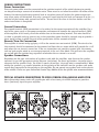
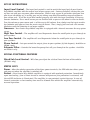
AMPLIFIER OWNERS MANUAL
INTRODUCTION
Dear Cerwin-Vega Mobile Customer,
Thank you for making Cerwin-Vega Mobile your choice for high performance car audio products. At
Cerwin-Vega Mobile, our goal is to produce products of unsurpassed quality. We believe you will not
find a better value anywhere in the mobile audio environment.
To ensure that your new Cerwin-Vega Mobile amplifier provides years of enjoyment, you should
consider having it installed by a professionally trained technician. They have the knowledge to make
your new amplifier perform its very best.
WARNING: Prolonged exposure to sound pressure levels in excess of 100dB can cause permanent
hearing loss. Cerwin-Vega Mobile amplifiers can exceed that level so please exercise restraint when
listening and enjoying your new amplifier.
GENERAL PRECAUTIONS
• This unit is designed for negative ground 12V DC operation only.
• Total system impedance must not be less than (2ohms for SX220.2 & SX440.4)(1ohm for SX500.1).
• Avoid installing the unit where:
- It would be subject to high temperatures, such as from direct sunlight or hot air from the heater.
- It would be exposed to rain or moisture.
- It would be subject to dust or dirt.
• Do not cover the unit with carpet or wires.
• Do not use the unit with a weak auto battery. Optimum performance depends on a normal battery
supply voltage.
• For safety reasons, keep the volume of your car audio system moderate while driving your vehicle
so that you can still hear normal traffic sounds outside your car.
MOUNTING PRECAUTIONS
Although Cerwin-Vega Mobile amplifiers incorporate heat sinks and protection circuits, mounting
the amplifier in a tight space without any air movement can still damage internal circuitry over time.
Choose a location that provides adequate ventilation around the amplifier. For easy system set-up,
mount the amplifier so the side panel controls will be accessible after installation. In addition, observe the following precautions:
1. For the most efficient cooling, mount the amplifier so that air runs along the length of the fins
rather than across them. Remember, any moving air across the amplifier will reduce heat.
2. Mount the amplifier on a solid surface. Avoid mounting to subwoofer enclosures or areas prone to
vibration. Do not install the amplifier on plastic or other combustible materials.
3. Prior to mounting the amplifier, make sure not to cut or drill into the fuel tank, fuel lines, brake
lines (under chassis) or electrical wiring.
WIRING PRECAUTIONS
1. Before installation, make sure the source unit power switch is in the OFF position.
2. Disconnect the negative (-) lead of the battery before making any power connections.
3. When making connections, be sure that each one is clean and secure. Insulate all of your connections. Failure to do so may damage your equipment.
4. A secure clean ground connection is critical to the performance of your amplifier. Connect the
ground directly to the car chassis to minimize resistance and avoid any noise problems.
5. Add an external fuse on the amplifier’s positive (+) power lead and connect it as close as possible
to the vehicle’s (+) battery terminal. Use a rating that equals the total current consumption at full
output of all amplifiers in the system. This external fuse will protect the vehicle from short circuits
that can cause a fire.
WIRING INSTRUCTIONS
Power Connection
The main power cable must be connected to the positive terminal of the vehicle battery to provide
an adequate voltage source and minimize noise. There must be an inline fuse within 18 inches of the
battery. Connecting the battery terminal lead to any other point will reduce the power output and
may cause noise and distortion. Use only 4 gauge or larger wire for this lead and connect it to the (+)
terminal of the battery with system fuse inline. Do not install the fuse in the fuse holder until the
entire installation is completed.
Ground Connection
The ground terminal (GND) connection is also critical to the correct operation of the amplifier. Use a
wire of the same gauge as the power connection and connect it between the ground terminal (GND)
of the amplifier and a metal part of the vehicle close to the mounting location. This wire should be
as short as possible and any paint or rust at the grounding point should be scraped away to provide a
clean metal surface to which the end of the ground wire can be screwed or bolted.
Remote Turn-On Connection
The amplifier is turned on by applying +12V to the remote turn-on terminal (REM). The wire lead to
this terminal should be connected to the remote lead from the car stereo which will provide the +12V
only when the car stereo is turned on. If the car stereo does not provide a remote lead, the remote
turn-on lead may be wired to an accessory terminal in the car’s fuse block. This will turn the amplifier
on and off with the ignition key, regardless of whether the car stereo is on or off.
Speaker Connections
Depending on the type and number of speakers used with the amplifier, wire them to the speaker
terminals as per the appropriate wiring diagram (see below). For most applications 18 gauge wire is
adequate for the speaker leads. For leads in excess of ten feet, 16 gauge wire is recommended. When
wiring the speakers, pay careful attention to the polarity of the terminals on the speakers and make
certain they correspond to the polarity on the amplifier. Do not ground any speaker leads to the chassis
of the vehicle. Please see your authorized Cerwin-Vega Mobile dealer for specific wire recommendations.
RIGHT
LEFT
REAR
RIGHT
LEFT
FRONT
REAR
FRONT
TYPICAL SPEAKER CONNECTIONS TO YOUR CERWIN-VEGA MOBILE AMPLIFIER
Most aftermarket source units will provide you with at least one pair of RCA
outputs to provide
a
RF FULL RANGE
LF FULL RANGE
clean (low-level) input for your amplifier.
RR FULL RANGE
RIGHT
RIGHT
RIGHT
LEFT
LR FULL RANGE
LEFT
LEFT
REAR
REAR
RIGHT
LEFT
FRONT
FRONT
REAR
FRONT
RF FULL RANGE
LF FULL RANGE
RF FULL RANGE
RR FULL RANGE
LF FULL RANGE
LR FULL RANGE
RR FULL RANGE
RIGHT
LEFT
SX440.4
SX440.4
RIGHT
LEFT
LR FULL RANGE
SX220.2
REAR
RIGHT
LEFT
SX500.1
RIGHT
FRONT
REAR
FRONT
RF FULL RANGE
LE
SET-UP INSTRUCTIONS
Input Level Control – The input level control is used to match the input level of your Cerwin-
Vega Mobile amplifier with the output level of your source unit. Contrary to belief, turning the gain
up does not give your any more power whatsoever. While it may appear to get louder when you turn
your input sensitivity up, in reality, you are just taking away from the working range of volume on
your source unit. To set the input level control properly, start with the input sensitivity all the way
counter clockwise. Use a music source you are familiar with so you can tell when it starts to distort.
Turn the volume on your source unit I of the way to full volume, then slowly turn the input sensitivity clockwise until you can hear the music start to distort. Then, simply just turn back a bit counter
clockwise until the distortion is no longer audible.
Crossover – Your Cerwin-Vega Mobile amplifier is equipped with a internal crossover for easy system
set-up.
High Pass Control – The amplifier will send frequencies above the cutoff point to pass through to
your speakers.
Low Pass Control – The amplifier will send frequencies below the cutoff point to pass through to
your speakers.
Phase Control – Lets you control the output phase to your speakers (0/180 degrees). Available on
SX500.1 only.
Subsonic Filter – Controls the lowest frequency that will pass through to the speaker. Available
on SX500.1 only.
SPECIAL FUNCTIONAL FEATURES
Wired Sub Level Control – Will allow you adjust the sub level from the front of the vehicle.
(SX500.1 only)
STATUS LED’S
Power - After the orderly connection of the three power terminals, the LED indicator shines green
and goes out when the amplifier is switched off.
Protect - Your Cerwin-Vega Mobile amplifier is equipped with overload protection. Immediately
upon overloading, (due to short circuit or extreme temperature) the protection is activated, and
the red LED indicator is illuminated. The amplifier is now protected against damage. In case of
thermal protection a short cooling time must be allowed after which the amplifier automatically
resumes operation.
QUICK TROUBLESHOOTING GUIDE
No Power: Check that all the fuses are good. If so check to be sure that the remote turn on lead is
properly connected, and that both Power and Ground connections are secure.
No Sound: Check to make sure input cables (RCA) are installed properly. Also, check all speaker
connections both at the amplifier and at the speaker itself.
No Sound / Red LED: Check that the speaker leads are not touching each other or the vehicle
chassis. Be sure the total impedance of the speakers is not too low for the configuration.
Poor Sound Quality (Distortions): Check the amplifier Input Sensitivity setting. It may need
to be turned down (counter clockwise). Check that the speaker wires are not touching the vehicle
chassis. Verify that the vehicle battery is properly charged.
Weak Bass: One or more speaker connections (+ and -) are reversed or are wired out of phase.
PRODUCT SPECIFICATIONS
SX220.2
SX440.4
SX500.1
RMS Power Rating
4 Ohm @14.4v
65 x 2
65 x 4
200 x 1
2 Ohm @14.4v
110 x 2
110 x 4
350 x 1
1 Ohm @14.4v
n/a
n/a
500 x 1
4 Ohm Bridged
220 x 1
220 x 2
n/a
Power Supply
Full PWM
Full PWM
Full PWM
Topology
Class D
Class D
Class D
Frequency Response
20Hz-30KHz
20Hz-30KHz
20Hz-250Hz
Battery Voltage Range for Operation
10.8VDC - 15.0VDC
10.8VDC - 15.0VDC
10.8VDC - 15.0VDC
S/N Ratio
>80dB
>80dB
>85dB
<0.2%
<0.2%
<0.2%
Total Harmonic Distortion
THD 4 Ohm per Channel
THD 2 Ohm per Channel
<0.4%
<0.4%
<0.4%
THD 1 Ohm per Channel
<0.7%
<0.7%
<0.7%
150mV - 5V
150mV - 5V
150mV - 5V
22K Ohm
22K Ohm
22K Ohm
Variable High-Pass
50Hz - 250Hz
50Hz - 250Hz
n/a
Variable Low-Pass
50Hz - 250Hz
50Hz - 250Hz
50Hz - 250Hz
25A
(2) x 20A
(2) x 25A
(6.6”)x(7”)x(1.85”)
(9.35”)x(7”)x(1.85”)
(9.35”)x(7”)x(1.85”)
Input Sensitivity
Low Input Level
Input Impedance
Low Input Level
Crossover
Fuses
Dimensions
(L) X (W) X (H)
$)"//&-".1-*'*&349
1
4
3
2
6
5
7
9
8
10
$)"//&-".1-*'*&349
1
7
2
3
6
5
4
8
10
9
.0/0#-0$,".1-*'*&3449
11
4
3
12
13
14
6
7
1
8
9
10
1
Status LED’s - These lights indicate when the amplifier is powered up normally and when there
is a protection fault (SX500.1 Only). See the “Troubleshooting” section for details on what these
useful indicators can tell you if there’s a problem.
2
HPF Crossover Adjustment- Use this adjustment to select the crossover point. Remember that
you must select the High Pass position (HPF) of the crossover adjustment switch first. The range
of adjustment is limited between 50-250 Hz.
3
Vega Bass - This control adds 0 to +12dB of boost at 45Hz (On the SX500.1 the frequency is
variable). Be cautious when adding boost to some subwoofer systems as they may not be able to
handle the additional low frequency boost. In the 0dB position, no bass boost is added.
4
LPF Crossover Adjustment- Use this adjustment to select the crossover point. Remember that
you must select the Low Pass position (LPF) of the crossover adjustment switch first. The range
of adjustment is limited between 50-250 Hz.
5
Crossover Selection Switch - This switch allows you to select the crossover. Use High Pass for
midrange or high frequency speakers. Use Low Pass for subwoofers. In the FLAT position, neither
crossover adjustment knob has an affect.
6
Input Gain Adjustment - This control matches the preamp stage of the Cerwin-Vega Mobile amplifier
to your source unit. This is NOT a volume control. The range is between 150mV and 5V.
7
RCA Input and Pass-Thru Output - These RCA jacks allow for a normal Left and Right channel
signal input. Simply connect to the source unit using RCA type audio cables, keeping them away
from power wiring wherever possible.
8
Power Input Connections - These connections are for input power, chassis ground, and remote
turn-on. Use a minimum of 4 gauge wiring for power and ground connections. The terminals will
handle up to 4 gauge wiring with no problem whatsoever. Be sure any wiring that passes through
metal has a grommet!
9
Power Fuses - Standard automotive type ATC/ATO fuses are used on Cerwin-Vega Mobile
amplifiers. Always replace with the correct fuse size. Never insert fuses of higher values. Doing
so will void the warranty of your Cerwin-Vega Mobile amplifier. Also include a main fuse at the
connection to the vehicle battery within 18 inches of the positive battery post. It is also important
to upgrade the connection between the negative battery post and the chassis of the vehicle. This
greatly reduces possibilities of weak electrical “links” in the circuit.
10
Speaker Output Terminals - Connect your speakers to these terminals. Stereo connections are
connected as labeled. Bridged connections use the LEFT + and RIGHT - as the two connections.
The 2 and 4 channel amplifiers will perform into 2 Ohm stereo loads or 4 Ohm bridged loads. DO
NOT run 2 Ohm bridged loads on these amplifiers!
11
Remote Level Control (SX500.1 Only) - This port is for the remote level control (included). The
control is intended to allow the user to control the level of gain up to the maximum adjustment
level set on the amplifier. The control does not add additional boost, it only attenuates the setting
that is fixed at the amplifier’s control panel.
12
Vega Bass Frequency EQ - Use this adjustment to select the specific frequency that your Vega
Bass will boost (40Hz - 100Hz)
13
Phase Adjustment (SX500.1 Only) - This control allows you to adjust the phase of your subwoofer
in time with your mids and tweeters. 0 or 180 degrees of adjustment capability. This is EXTREMELY
useful to get the best and most bass out of your system.
14
Sub-Sonic Adjustment (SX500.1 Only) - This control allows you to remove the unwanted sub-sonic
frequencies below the tuning frequency of a ported enclosure. This helps to protect the woofer
from over excursion.
Warranty
Cerwin-Vega Mobile warrants all amplifiers and speakers to be free of defects in
material or workmanship for a period of 1 year.
Warranty Procedure:
Cerwin-Vega Mobile strongly suggests all warranty claims should be handled
through an authorized dealer. Because of the technical nature of our products,
performance problems can often be the result of improper usage or installation.
An authorized retailer can help determine if this is the case and will save you the
time of returning an item that is not actually defective.
For all VEGA subwoofer models the cone is to be removed from the basket as completely as possible. Cut the surround and then the spider. After this, the cone should
lift out.
For VEGA coaxial models, the tweeter needs to be broken off and sent in with the
cone.
All returns must have the serial number taped to the cone. The serial number can
be found on the basket on all speakers and underneath the spider attached to the
top of the magnet plate.
Please remove the sticker and tape it to the cone. This process will save everyone
on shipping costs and allow us to check and replace speakers much faster.
For all VMAX models as well as all amplifier models, the defective unit needs to be
returned. For speaker systems such as VMAX component models only return the
defective part (i.e midbass, tweeter or crossover).
Shipping:
Once you have your RA number, ship your return to:
Cerwin-Vega Mobile
ATTN: Customer Service Dept.
6915 W. Frye Road
Chandler, AZ 85226
When we receive your return, we will process your order. Please make sure that you
clearly mark the RA number on the outside of the box and on the shipping label.
If the RA number is not on the outside of box/label, it will be returned to sender!
Specifications subject to change without notice.
121807
6915 W. Frye Road
Chandler, AZ 85226
480 838 9422 • 480 491 1201 [fax]
www.cerwinvegamobile.com