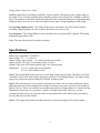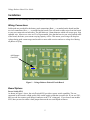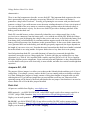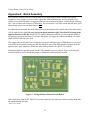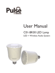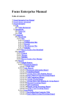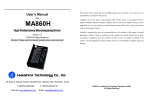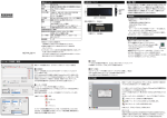
1
LiFePO4 2S Voltage Reducer Board
User Guide
Revision History
Date/Who
Description
Dec 12, 2011 / CJB
First production user guide release.
Liability Disclaimer
The developer has used his best engineering judgment, skills, and experience to design a voltage reducing solution
intended for use in RC sailplanes using LiFePO4 2S battery packs. Under no circumstances will EMFScan.com LLC or
Chris Bajorek be responsible for specific outcomes of the use of this board in your planes, be they intended or
unintended uses. It is therefore of the utmost importance that you follow the recommended pre-flight test guidelines
after installing this board. The act of installing this board in your plane(s) signifies your agreement that you assume
full responsibility for the ultimate outcomes when using this board.
Voltage Reducer Board User Guide
Table of Contents
Revision History....................................................................................................................................1
Liability Disclaimer...............................................................................................................................1
Contact Information.............................................................................................................................. 2
Voltage Reducer Board Overview..............................................................................................................3
Voltage Reducer Benefits......................................................................................................................3
Specifications.............................................................................................................................................4
Installation..................................................................................................................................................5
Wiring Connections...............................................................................................................................5
Board Options........................................................................................................................................5
IMPORTANT!! Pre-Flight Testing Required.......................................................................................6
Theory of Operation...................................................................................................................................7
Circuit Description................................................................................................................................8
Jumpers JU1, JU2.............................................................................................................................9
Parts List................................................................................................................................................9
Maintenance............................................................................................................................................. 11
Problems and Solutions............................................................................................................................11
Credits...................................................................................................................................................... 11
Appendix A: Board Assembly ................................................................................................................12
Contact Information
Orders and Technical Support
Email me with your questions and I'll either respond back via email or by phone or SMS if you leave
your number. Thanks!
Chris Bajorek
[email protected]
RC Groups: SoaringDude
2
Voltage Reducer Board User Guide
Voltage Reducer Board Overview
More and more RC sailplane enthusiasts are using LiFePO4 (“LiFe”) 2S receiver battery packs because
they offer superior energy density, very low self-discharge rates, and a fairly flat discharge curve.
Unfortunately very few popular servos are yet available in versions that can safely be used with straight
LiFe packs since their output voltage exceeds the typical 6.0v maximum rating for servo supply
voltage. Worse case, LiFe packs right off the charger can have output voltages that exceed 7.0v. While
these levels drop quickly to 6.8-6.9v after being put into active use, the voltage output for most of the
discharge curve still exceeds 6.6v.
Popular solutions to this too-high voltage problem for LiFe packs are either to use an RC voltage
regulator or to use NiMH battery packs.
The Voltage Reducer board was designed to reliably drop LiFe 2S pack voltage to a safe level for
standard servos that are rated for a 6.0v maximum voltage. Since one of the more popular servo
manufacturers (as of this writing) is MKS, they were contacted to get their official take on what
voltages are safe to use for their servo product line. Here are direct extracts from an email answer
received from Tom at MKS on Nov 4, 2011:
"MKS recommends to keep the voltage below 6v. ... MKS recommends a voltage between 5.55.8v for maximum performance."
So the Voltage Reducer board was designed to deliver those voltages which should also work well with
all other popular “6 volt maximum” or “6.6 volt maximum”servos.
Voltage Reducer Benefits
There are definite advantages to using the Voltage Reducer board over a typical RC voltage regulator:
Size. The board is a thin 1.2" x 2.1", the parts are low profile surface mount diodes which do not need
a heat sink, and the board can accept an optional sealed high quality toggle power switch.
Intrinsically more reliable. The Voltage Reducer is constructed solely using two pairs of high current
capacity diodes. No transistors, integrated circuits, or support components are used. The diodes run
cool to the touch under even relatively high continuous current loads. Thus, the Voltage Regulator
board is considerably more reliable than any voltage regulator solution.
More voltage to your servos. For a typical LiFe 2S battery pack, your servos will get more usable
voltage as compared to many regulators with a fixed output voltage. This means your servos will
deliver better speed and torque performance.
Better current capacity. There is no hard current limit imposed by the Voltage Reducer as compared
to regulators so short periods of high current surge as in launch zooms or high-G maneuvers are
3
Voltage Reducer Board User Guide
handled without limits. Exceeding a regulator's current capacity will typically cause voltage drops on
the output. If you exceed a regulator's power handling capacity for too long (like a binding or defective
servo), the regulator could enter a thermal limiting state; this would either then pass unregulated battery
voltage to the receiver/servos or reduce the output current and/or voltage depending on the design.
No switching regulator noise. The Voltage Reducer does not produce any RF or electrical noise;
switching voltage regulators do and can induce interference in your receiver.
Less lost power. The Voltage Reducer circuit consumes less power than an RC regulator. This means
potentially longer battery runs.
Cost. The cost of this board is less than a regulator.
Specifications
Battery types supported: LiFePO4 2S
Input voltage: 5.8 – 7.5v (Note 1)
Output voltage: Input voltage – 1.2v (under typical 6-servo loads)
Output current: 20A surge, 5A continuous (Note 2, Note 3)
Weight: 13g/0.46oz with switch installed, 9g/0.32oz without switch
Dimensions: 54 x 32 x 9.8mm with switch installed
54 x 32 x 7mm without switch
Note 1: The Voltage Reducer does not have a strict input voltage drop out limit. Thus there are no bad
“threshold” effects if the input voltage sags due to a defective or discharged battery. The input voltage
range given reflects the expected range for LiFePO4 2S battery packs.
Note 2: The vast majority of 6 servo planes will require less than 0.6A of average continuous current
although typical servo loads during launch or high G maneuvers can cause very short current spikes as
high as 8 to 10A. There is no artificial current limit imposed by the Voltage Reducer. As such it will not
immediately shut down if you experience a failed servo high current fault. This gives you the
maximum possible time to get your plane back on the ground with such a failure before your battery
runs dry and you lose radio control.
Note 3: The output load current is divided across two series-paired strings of 10A power diodes.
4
Voltage Reducer Board User Guide
Installation
(for those who are soldering their own board, please refer to Appendix A for details)
Wiring Connections
Solder pads are provided for the battery pack connections (Batt +, LM as marked on the board) and the
receiver connections (Rcvr + , LM as marked on the board). You will need to solder wires from the board
to your own connectors on both sides. The drill holes are 1.8mm diameter which will accept up to 16ga
stranded wire. Most servo wires are 22 to 24ga stranded. Note that the heavier your wires on both ends
of the board, the better your current carrying capacity will be. This means your wiring will drop less
voltage during peak current surges and result in a more stable receiver and servo voltage level during
all phases of flying.
Add Jumper
if no SW1
Figure 1 – Voltage Reducer Printed Circuit Board
Board Options
Power Switch SW1
As shown in Figure 1 above, the on/off switch SW1 provides a power switch capability. The one
supported by this board is a high quality fully sealed toggle switch that is rated at 6A. If you use SW1,
then you can also connect your charger connector to the “Ch” wiring pad. If you chose to not include
SW1, then you need to solder a short jumper between the two switch pads as shown.
5
Voltage Reducer Board User Guide
Diode Jumpers JU1, JU2
The standard board is delivered with all 5 diodes installed and with no JU1 or JU2 jumpers installed. If
you are using all 6.6v servos and don't need the full 1.2v drop that the standard board provides, you can
optionally solder in wire jumpers across the JU1 and JU2 pads. This will short out diodes D2 and D4
and reduce the voltage drop to ~0.8v. Note that you must install both jumpers if you want this lower
voltage drop option.
IMPORTANT NOTE ON YOUR PLANE'S RECEIVER IDLE CURRENT
Be aware that there needs to be enough current flowing at all times (even during idle when no servos
are moving) to bias the diodes and allow them to drop a consistent amount of voltage. If your setup is
drawing less than about 50mA at idle, you may not get consistent voltage drops across the diode
pairs. That is why pre-flight testing is important before you actually fly for the first time with the
Voltage Reducer.1
IMPORTANT!! Pre-Flight Testing Required
AFTER INSTALLING THIS BOARD BUT BEFORE YOU FLY YOUR PLANE:
First fully charge your battery and perform at least a full 15 to 30 minutes of continuous simulated
flying, moving the servos slowly and quickly as in real flight, and carefully watching all control
surfaces for any unusual movement, flutter, chatter, buzzing, or hesitation. During this test also grab
your fuselage and give it a few good firm twists and shakes to simulate bumpy conditions and shakes
during landing; this may expose a bad connector or wiring connection. Make sure all your servos are
behaving normally. Better to find any problems on the ground.
1 A simple solution to the rare case of too little idle current is to solder a small resistor across the Rcvr + (J2A) and Rcvr LM
(J2B) pads which will increase the idle current. If needed, the value will have negligible impact on your battery pack's
run time. Contact us for support assistance if your pre-flight tests suggest too little idle current.
6
Voltage Reducer Board User Guide
Theory of Operation
This section gives an overview of how the Voltage Reducer board does its job. This board does not
perform a voltage regulation function; instead it always subtracts a fixed amount of voltage depending
on the diodes used. The standard Voltage Reducer board delivers approximately 1.2v less than the LiFe
2S battery pack voltage. Since the overall goal of this board is to protect your servos from battery pack
voltages that exceed 6.0v, even a typical LiFe 2S battery pack that just comes off a charger at 7.1-7.2v
will still deliver ~6.0v to the receiver and servos. See the Voltage Drop Plot below for an idea of how
the receiver/servo voltage varies with battery pack voltage. Note that the X axis in the graph is not
linear; it has compressed ranges between some X axis voltage values. The overall goal is to show how
the receiver voltage varies across the usable LiFe 2S discharge curve.
Figure 2 – Typical Voltage Drop Performance
7
Voltage Reducer Board User Guide
Circuit Description
(Please refer to the schematic diagram in Figure 3 below. A parts list is available at the end of this
section.)
Your LiFePO4 2S battery pack + and – wires are connected to the board via the Batt + (J1B2) and Batt
– (J1C) wire pads respectively. In the ON position, battery voltage is fed through SW1 pin 3 to the
diode circuit. In the OFF position you can connect your battery to an external charger if wired with the
appropriate connector. Note that SW1 is optional; if you have omitted it on your board, then you would
need to solder the SW1 wire jumper as shown in the Installation section.
The Voltage Reducer routes the battery through two parallel pairs of diodes to the receiver V+ wire
pad: pair D1 + D2, and pair D3 + D4. Each of these is a high current rectifier diode rated at 10A. Each
diode pair is designed to drop the same required amount of voltage (~1.2v). The reason for two parallel
pairs is two-fold: (1) current load balancing, and (2) circuit redundancy. Under normal operation any
single diode pair would be able to handle even unusually high combined servo current spikes. Adding a
second parallel pair ensures that each pair will only carry approximately half of the full current load.
Additionally, in the unlikely event that any single diode fails open circuit, the other diode pair would
continue to operate and deliver reduced voltage normally.
Figure 3 – Schematic Diagram, LiFe 2S Voltage Reducer Board
A word about diode selection for this board. You cannot choose just any 10A rectifier diode and expect
them to work in this application. We are using standard silicon junction power diodes for D1 and D3
that drop about 0.75v; for diodes D2 and D4 we are using Schottky junction power diodes that drop
about 0.45v. Thus the combined total voltage drop is 1.1-1.2v. These diodes are also selected to require
only a nominal amount of idle current to properly bias them for their desired voltage drop
2 Note that the wire pad 'J' designations from the schematic are not shown on the board silkscreen.
8
Voltage Reducer Board User Guide
characteristics.
There is one final component to describe: reverse diode D5. This important diode suppresses the noise
that is generated by the servos when they are moving. When a DC servo motor is in motion, it
generates a voltage called "back emf." Actually, just spinning the servo motor with your hand would
generate a voltage if you could measure across the motor windings themselves. From a circuit point of
view you can think of the servo motor as a transient voltage generator where the induced voltage is
proportional to the motor's velocity. So, the reverse diode D5 provides a discharge path back to the
battery pack for that back emf.
Diode D5 is needed because we have electrically isolated the servo voltage supply line (via the
receiver's servo connectors) from the battery pack + wire with the two diode pairs. While the Voltage
Reducer does a great job dropping the voltage to the receiver and servos, it also blocks the battery pack
from doing what it would normally do: terminate and thus suppress much of the back emf since the
battery pack itself presents a low impedance to this generated noise. So the reverse diode connects the
servo-generated back emf to the battery pack and thus gets greatly suppressed (the degree depends on
the length of your servo wires, etc). Note that the actual current that this diode has to handle is minimal
but on this board we are using another 10A power diode since we buy those devices in quantity.
One final point about diode D5: you could eliminate it if instead you connected the right filter
capacitor(s) across the receiver voltage supply line. To do the job right you would need a very large
capacitance (e.g. 2200 uF 10v) in parallel with a smaller capacitor (0.01uF or 0.1uF 50v) to suppress
the higher frequency noise components. From our bench tests and flight time we have determined that
a reverse diode works just as well electrically, is more reliable, and takes less vertical board height than
capacitors.
Jumpers JU1, JU2
The purpose of these jumpers is to allow you to short out the Schottky diodes and thus get 0.4v less of
voltage drop. For example, you may want to do this if you are running with servos that have a higher
6.6v limit. Adding these jumpers is simply a matter of using short lengths of stripped solid wire and
soldering them in. If you add one jumper then you must add the second one too, otherwise all the
operating current will be borne by the diode path that has the one jumper. Note that there is no need to
remove diodes D2 or D4 with these jumpers installed.
Parts List
All parts are available from Digikey www.digikey.com
SW1 (optional) – p/n M2012SA2W30-ND, sealed SPDT toggle switch, silver contacts, rated 6A at
125VAC (Mfgr: NKK; Datasheet: http://www.nkkswitches.com/pdf/MtogglesAnglePC.pdf)
Digikey cost in small quantities: ~$4.40 + shipping
D1, D3, D5 – p/n S10A-TPMSCT-ND, 10 amp silicon rectifier 50v PRV, surface mount package
(Mfgr: MCC; Datasheet: http://61.222.192.61/mccsemi/up_pdf/S10A~S10M%28HSMC%29.PDF)
Digikey cost in small quantities: ~$0.53 each + shipping
9
Voltage Reducer Board User Guide
D2, D4 – p/n SK106-TPCT-ND, 10 amp Schottky rectifier, 60v PRV, surface mount package
(Mfgr: MCC; Datasheet: http://61.222.192.61/mccsemi/up_pdf/SK102-SK1010%28HSMC%29.PDF )
Digikey cost in small quantities: ~$1.00 each + shipping
10
Voltage Reducer Board User Guide
Maintenance
The only maintenance task is to occasionally (twice a year is suggested) verify that both diode pairs
D1-D2 and D3-D4 are functioning. Since the board was designed to safely work even if only a single
diode pair is good, it's possible that you could (safely) run for a long time under this condition without
knowing it.
The simplest way to do this test is to turn your plane power on and using a digital voltmeter check the
voltage across each diode in both pairs. There is enough room to put small voltmeter probes on the
metal leads on each side of the diodes. Across each of the diodes D1 and D3 you should see a voltage
drop of ~0.75v +/– 0.1v. Across each of the diodes D2 and D4 you should see a voltage drop of ~0.4v
+/– 0.1v. If any diode is defective you will likely see 0v across it indicating that either no current is
flowing in that pair, or that one of the diodes may be shorted. Diagnose further if any diode reads 0v.
Problems and Solutions
Problem/Symptom
Possible Solution
No servo or receiver activity when ON
1. Re-check the wiring to your battery pack and
receiver.
2. If no SW1 is used, make sure you have installed
the jumper as illustrated in the Installation section.
One or more servos acting erratically
1. Turn the plane's power on. Using a digital
voltmeter, observe the voltage across the “Rcvr + -”
pads and verify that you are seeing a fairly steady
voltage while you move the servos. It should be 1.1
to 1.2v less than the battery pack voltage. If the
voltage is varying quite a bit when going from idle to
servos moving, your combined receiver and servos
combination may not have enough idle current to
keep the diodes biased on. If you can, measure
your receiver idle current and contact us with the
current and Rcvr voltage levels you are seeing. We
may suggest soldering a small resistor across the
Rcvr +- pads to ensure minimum idle current.
Credits
Special thanks to RC Groups “Flo” in Munich for his initial description in 2010 of this voltage
reduction solution concept. Thanks also to all the RC Groups Sailplane forum members who offered
their insights and helped validate this solution.
11
Voltage Reducer Board User Guide
Appendix A: Board Assembly
This section is for those who are building their own Voltage Reducer from a blank board. Board
assembly is fairly simple if you have basic experience with soldering larger surface mount devices
(SMD). If you need help then it is suggested that you do an Internet search on “surface mount soldering
tips.” One excellent text reference is found here. You can also do a YouTube search and find some good
instructional videos (one excellent video is here).
For all diodes on the board, the small white silkscreen dot indicates the cathode side of the diode which
will be marked with a band. Be sure you get the diode polarities right! Note that D5 is facing in the
opposite direction of D1-D4. Diodes D1, D3, and D5 should be centered over the pads and soldered
by applying a generous amount of “no-clean” flux before you apply the soldering iron heat. Very little
solder will be needed for each lead.
The copper pads for D2 and D4 are designed to accept two different types of SMD diodes so you need
to be a little more careful to make sure that the underside part of the diode pins do not short out to the
opposite side's pads. Otherwise follow the same solder procedure as with D1, D3, and D5.
Install and solder the optional switch into the SW1 position if you are using it. If you are leaving the
switch off, then be sure to install the jumper as illustrated in the Installation section.
Figure 4 – Voltage Reducer Printed Circuit Board
Only install wire jumpers JU1 and JU2 if you know ahead of time that you want less voltage drop than
the standard board provides.
--End of User Guide--
12