1
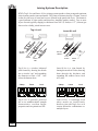
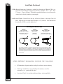
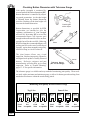
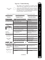
Patented
Sheet Metal Joining Systems
Cross Section of a
Lance-N-Loc Joint
Cross Section of a
Tog-L-Loc Joint
Tog-L-Loc & Lance-N-Loc are protected by patents
in the U.S.A. and most other industrialized nations.
Tog-L-Loc & Lance-N-Loc are registered
trademarks of BTM Corporation, Marysville,
Michigan U.S.A.
Contents
Joining Systems Description------------------------------------------------- Page 2
Tog-L-Loc Basics-------------------------------------------------------------- Pages 3-4
Joint Data----------------------------------------------------------------------- Pages 5-6
Joining Theory and Quality Control----------------------------------------- Page 7
Maintaining Joint Quality ---------------------------------------------------- Page 7
Checking Button Dimension With A Tolerance Gauge------------------- Page 8
Maintenance & Adjustment-------------------------------------------------- Page 9
Changing The Die Blades---------------------------------------------------- Pages 10-12
Troubleshooting---------------------------------------------------------------- Pages 13-15
Tooling Record----------------------------------------------------------------- Page 16
®
CORPORATION
BTM Corporation 300 Davis Road Marysville, Michigan 48040 U.S.A.
Phone 810-364-4567 • Fax 810-364-6178
Revised 042508
User's Guide for Tooling
BTM's
Tog-L-Loc® and Lance-N-Loc®
Joining Systems Description
BTM’s Tog-L-Loc and Lance-N-Loc joining systems produce clean, strong and consistent
joints in most coated or uncoated metals. The joints are characterized by a “button” formed
on the die side layer of metal and a recess formed in the punch side layer. The button is
a good indicator of joint quality and therefore, simplifies quality control. Two or more
layers of metal typically ranging in thickness from .008” (0.2mm) to .157” (4.0mm) per
sheet can be reliably joined in most cases.
Tog-L-Loc®
Die Side
''Button''
Die Side
''Button''
Cross
Section
o
Cross
Section
Punch
Side
Tog-L-Loc is a circular, leakproof
joint formed by drawing the metals
into a circular “cup” and expanding
the diameter to form a 360o lock
below the bottom sheet.
Clamp
Draw
Lock
Tog-L-Loc is generally preferred
due to its omnidirectional strength
characteristics, excellent fatigue
properties and exceptional tool life.
Page 2
Lance-N-Loc®
Punch
Side
Lance-N-Loc is a joint formed by
lancing the metals on 2 sides, drawing
them through the thickness and
expanding the width to form a lock
on 2 sides.
Clamp
Lance
Lock
Lance-N-Loc is commonly used
where metals are insufficiently
ductile to join with Tog-L-Loc or in
certain dissimilar combinations or
multiple layers.
Tog-L-Loc Basics
A Tog-L-Loc / Lance-N-Loc system consists of 5 major components.
2. The Force Frame:
Forces must be contained to prohibit flexing
at the punch / die. Deflection will cause
degraded joint strength and tool breakage.
1.
2.
4.
3.
5.
3. The Tog-L-Loc / Lance-N-Loc Punch:
Tog-L-Loc punches are available in various tip
diameters (see joint size page 5), lengths and
styles to suit differing application requirements.
The perimeter of the round Tog-L-Loc punch tip has a slight radius to prevent piercing.
Lance-N-Loc punches are also available in various lengths and styles. The square LanceN-Loc punch tip has cutting edges on two sides and angular ramps on the other two.
(Tog-L-Loc Basics continued on following page.)
Tog-L-Loc 940
BTM Ball Washer
Tog-L-Loc Punches
Screw
Lance-N-Loc Punches
Ball Lock
Standard
Tog-L-Loc & Lance-N-Loc Metal Joining Systems
1. The Force Mechanism:
A device capable of producing sufficient force
to form the joint(s). Hydraulic, pneumatic or
mechanical presses are generally used.
Standard
Ball Lock
Page 3
4. The Stripper:
Both Tog-L-Loc
and Lance-N-Loc
require use of a spring
stripper / clamping
mechanism which
surrounds the punch
tip. The stripper
must preload the
parts before punch
entry, and must allow
full punch travel. The
spring force must be
sufficient to clamp the
parts together during
joining and prohibit
upward extrusion of
the metal around the
punch.
Tog-L-Loc Basics Continued
Double Spring
Stripper Assembly
Preferred
Stripper Assembly
940
Stripper Assembly
5. The Tog-L-Loc / Lance-N-Loc Die:
Tog-L-Loc dies are available in many styles to suit differing application requirements. The
dies have a fixed anvil which is recessed from movable or pivoting blades. A radius is
given to the blades' inside edge. Dies are retained by ball lock, set screws or socket head
cap screws. The 940 Tog-L-Loc and Lance-N-Loc dies feature a one piece anvil and shield.
A spring is used to close the 940 blades.
Lance-N-Loc dies are also available in various styles, however, all are two bladed. The
blades have cutting edges to the inside, with a fixed anvil recessed from the blade surface.
Blade shields are supplied with several die styles. These shields protect the die blades from
the force of the stripper and help to retain the blade assembly to the die. In some cases, dies
are mounted in pockets within a block which functions as the shield.
940 Lance-N-Loc Die
(Preferred Tooling)
Tog-L-Loc (Preferred)
Die 3 blades and
elastomeric ring
The spherical retainer is
positioned here in this pocket.
The retainer and screw hold
the die in place.
BTM
Spherical
Retainer
Tog-L-Loc
(Special Dies)
Page 4
940 Tog-L-Loc
3 Bladed Dies
(Preferred Tooling)
Lance N-Loc
(Special Dies)
Joint Data
BTM sheet metal joining tools are furnished with joint data documentation
expressed in the following terms.
Punch
940 Style Tog-L-Loc
940 Style Lance-N-Loc
Punch
Stripper
Stripper
PTR
Joint
Size
Joint
BD
Joint
Size
Joint
BD
(Button Dimension)
(Button Dimension)
AD
AD
(Anvil
Depth)
(Anvil
Depth)
Die
Die
Elastomer Style Tog-L-Loc
Punch
Punch
Stripper
Stripper
PTR
Joint
Special Style Lance-N-Loc
Joint
BD
BD
(Button Dimension)
(Button Dimension)
AD
AD
Die
Joint
Size
Joint
Size
(Anvil
Depth)
Die
(Anvil
Depth)
Tog-L-Loc & Lance-N-Loc Metal Joining Systems
1. Joint Size: Expressed as the punch tip diameter (Tog-L-Loc) or width of the die anvil
(Lance-N-Loc). For example, a .18" Tog-L-Loc has a punch tip diameter of .180" (4.6mm).
Common sizes are: .12" (3.0mm), .18" (4.6mm) and .25" (6.4mm) with special sizes used
on occasion.
2. PTR: (Punch Tip Radius): Tog-L-Loc only. Expressed as a decimal figure example:
.010'' (0.25mm). This dimension is determined at BTM to suit the application.
Joint Data continued
Page 5
Joint Data Continued
3. BD (Button Dimension): Diameter or width of the formed joint ''Button.'' BD is expressed as a decimal figure and given a tolerance. Example: .295" + .010" -.000"
(7.49mm + .25mm -.000mm). This highly repeatable dimension is used for quality
control and is directly linked to joint strength.
4. AD (Anvil Depth): Depth from the top of the die blades to the top of the die
anvil. Expressed as a decimal figure Example: .035'' (0.9mm). This dimension is
determined at BTM to suit the application.
Measuring Button Dimension (BD)
2 Bladed
Tog-L-Loc® Die
BD=Maximum obtainable
measurement in direction
of blades opening
BD
3 Bladed
Tog-L-Loc® Die
BD=Minimum
obtainable
measurement
BD
2 Bladed
Lance-N-Loc® Die
BD=Minimum
obtainable measurement
in direction of blades opening
BD
Joint quality (strength) is monitored by measurement of the button dimension (BD).
Button dimension is controlled by adjusting punch penetration. Button dimensions
specified by BTM are intended to give the optimum combination of joint strength and
tool life. BD specification includes a tolerance to accomodate standard mill tolerances
in the metals.
OTHER PERTINENT INFORMATION INCLUDES THE FOLLOWING:
Page 6
1.
BTM numbers of punch and die tooling for reference and re-ordering.
2.
Metal type and thickness as specified by the customer, as well as
orientation - (i.e. punch side/die side.)
3.
Location of Tog-L-Loc tooling within machinery where applicable.
Joining Theory and Quality Control
In order to function reliably, a Tog-L-Loc or
Lance-N-Loc system must conform to the following guidelines.
The parts to be joined must allow adequate access for the tooling and mate without
gaps at the joint locations.
2.
The metals to be joined must be sufficiently ductile, within the thickness capabilities
of the system and the parts must conform to the tolerances the machine was designed
around.
3.
The machine must consistently produce sufficient force to form the joints.
4.
The machine must contain the force without excessive flexing.
5.
The stripper/clamp must apply sufficient force to contain the flow of metal within the
die.
6.
The tooling must be appropriate to the metals being joined, (i.e. Tog-L-Loc or
Lance-N-Loc, joint size, AD and PTR.) Tools purchased for one metal type and
thickness may not give the best results with a different metal.
7.
The tooling must be adjusted & aligned to properly form the joints, and be secured to
maintain these settings.
8.
The machine and tooling must be maintained properly so that all components perform
their intended function. For example, worn seals can reduce force output thereby
affecting joining ability.
Maintaining Joint Quality
The Lance-N-Loc Punch must have sharp angled edges. (See page 3 of this document.)
Lance-N-Loc die blades must be sharp to maintain consistent joint quality.
Correct anvil depth in Tog-L-Loc and Lance-N-Loc dies is required to obtain a
superior joint.
The force unit should be in proper operating condition. A unit in poor condition could
influence joint quality.
Tooling must be free from dirt, paint chips or sludge that may develop after long use.
Inspect tooling at weekly intervals to ensure punches and dies are clean.
Punch and die must be in proper alignment to form a good joint.
Inspect for weak, compressed or broken stripper springs and replace as necessary.
BTM recommends changing springs every 100,000 cycles or when changing tooling.
Tog-L-Loc & Lance-N-Loc Metal Joining Systems
1.
Page 7
Checking Button Dimension with Tolerance Gauge
Joint quality (strength) is monitored by
measurement of the button dimension (BD).
Button dimension is controlled by adjusting punch penetration. As the shut height
is adjusted down the button dimension
increases. Backing off the shut height will
decrease the button dimension.
Button dimensions, as specified by BTM
Corporation, are intended to give the
optimum combination of joint strength
and tool life. Increasing BD to exceed the
recommended figure will increase peel
strength without measurable effect on shear
strength, but will reduce tool life. Reducing
BD to less than the recommended figure will
prolong tool life at the cost of reduced peel
strength; again, shear strength is not greatly
affected as long as a lock is achieved.
The joint button allows easy visual
inspection. Broken, improperly adjusted or
misaligned tools produce visually distorted
buttons. Defective strippers and part
nonconformity will also show up in visual
inspection. Refer to “Trouble Shooting”
pages 13-15 for specific information.
Checking BD
with a caliper.
Shear
Max
Peel
Go
No Go
Tolerance Gauge
(Go - No Go Gauge)
Min
The tolerance gauge is a reliable and easy method of monitoring joint quality. These tools
are made with a maximum and minimum gauge to allow for button growth resulting from
standard mill tolerance within the metals being joined.
Monitoring Joint Quality With a Tolerance Gauge
Tog-L-Loc
MAX.
MAX.
(GO)
(NO GO)
(NO GO)
MIN.
MAX.
MAX.
(GO)
(NO GO)
(NO GO)
Good
Joint
Not
Acceptable
Good
Joint
Not
Acceptable
Good
Joint
Not
Acceptable
Good
Joint
Not
Acceptable
(GO)
Page 8
MIN.
Lance-N-Loc
(GO)
MIN.
MIN.
Maintenance & Adjustment
1. Tog-L-Loc tools are manufactured to be interchangeable so that replacing a punch and
or die will not require any shut height adjustment.
3. Machines should be properly maintained, as problems with seals, friction, lubrication,
loose or broken parts, cracks in the force frame, etc. can adversely affect the Tog-LLoc Joints.
4. If a problem with the Tog-L-Loc joints arises, use the following checklist before
adjusting tools. Tog-L-Loc tools are full hard, (Rockwell C-60 Range) and will not
usually require adjustment due to wear.
•Check part metals for thickness and hardness.
•Check for damage to punch and die.
•Check condition of stripper springs. (Replace after 100,000 cycles)
•Check operating pressure.
•Check machine controls sequence and positive down cycle.
•Check adjusting mechanism for loose parts.
•Check for flexing, yielding or damage within the force frame.
5.
We support our customers and want to know of any problems you may encounter. Should
you encounter problems with Tog-L-Loc tooling, call our service department. BTM
corporation has extensive experience with Tog-L-Loc in production environments, and
will provide expert support.
Caution:
Observe common safety practices when working
with any press tooling equipment.
Tog-L-Loc & Lance-N-Loc Metal Joining Systems
2. While periodic adjustment may be necessary, a machine which begins to require
frequent shut height adjustments is indicating a problem. Refer to items 3 and 4 below
for typical causes.
Page 9
Changing the Die Blades
7.
THREE BLADE TOG-L-LOC DIE ASSEMBLY:
1. Place the three blades on the anvil, surrounding the top.
2. Slide the elastomeric ring over the top of the blades and into its groove.
Blade
Anvil
Elastomeric
Ring
Die Body
Tog-L-Loc three blade
die assembly with elastomeric ring.
TWO BLADE TOG-L-LOC DIE ASSEMBLY:
1. Drive the roll pins out of the die body with a punch & hammer.
2. Remove the springs and die blades.
3. Replace with new die blades (and springs if necessary).
4. Replace new roll pins in die body.
Anvil
Anvil
Blade
Blade
Roll Pin
Roll Pin
Die Body
Spring
Body
Tog-L-Loc two blade die assembly
with internal spring.
Page 10
Tog-L-Loc two blade die assembly with
external springs.
Changing the Die Blades (continued)
940 TOG-L-LOC DIE ASSEMBLY (Canted Coil Spring)
Blade
Anvil
Spring
Top
View
Guard
Die Body
940 Die Springs
Clockwise Direction
3 blade 940 Style Die
940 LANCE-N-LOC DIE ASSEMBLY
Anvil
Blade
Elastomeric Ring
Die Body
Lance-N-Loc 2 blade die assembly.
940 TOG-L-LOC DIE ASSEMBLY (Elastomer)
To change the die blades in the 940 Elastomer Series dies, special tools (kit numbers
listed below) are required to effectively install the elastomer and blade assembly into
the die. It will be necessary to also replace the elastomer because it cannot be removed
without damaging it.
Size
Took Kit No.
Size
Tool Kit No.
3.0-940
711400J
5.5-940
741900N
3.0-940M
710200G
5.5-940M
747700K
3.8-940
793900J
6.4-940
711600N
4.6-940
711500L
6.4-940M
710500X
4.6-940M
710100U
7.6-940
779600P
Tog-L-Loc & Lance-N-Loc Metal Joining Systems
1. Remove spring with a small screw driver
or tool to pry the spring out.
2. Discard old spring. Springs cannot be reused.
3. Set new blades together in a circle on a flat surface.
4. Place spring over new blades and into groove.
Spring should flow around the blades in a clockwise direction.
5. Press spring and blade assembly over diameter of anvil, being careful
not to damage or pinch spring.
6. If spring is crimped, bent or breaks during assembly, replace with a new spring.
(A damaged spring will produce poor joint quality.)
Page 11
Changing the Die Blades (continued)
940 Elastomer Blade Assembly Instructions
1. First, remove the old elastomer by digging it out of the die with a pick or a small screwdriver.
2. Discard old elastomer as it cannot be reused.
3. Replace blades and install a new elastomer as detailed in the procedure outlined below:
Place 3 blade sections in assembly base with
bottom (larger outside diameter) of blade in
counterbore.
1
ASSEMBLY BASE
Place elastomer with groove facing down over
small end of assembly pin. Push down to
beginning of tapered portion of pin.
2
ASSEMBLY PIN
3
Place assembly pin and elastomer on top of blade
set with pilot diameter in assembly pin
surrounding the blades. Slide elastomer over
blades and remove assembly pin.
4
Remove blade sub-assembly from assembly base.
5
Place top of blade sub-assembly into pilot
diameter in assembly pin and lubricate elastomer
(light oil).
6
Push blade sub-assembly into tapered hole in
assembly base until it reaches counterbore (for die
assembly).
7
8
9
Page 12
Place counterbore at end of assembly base over
top of guard on die assembly.
Push assembly pin until the blade assembly snaps
past guard and is retained in die assembly. Repeat
steps 1-8 as required.
Install assembly pin in assembly base as shown for
storage when not in use.
Tog-L-Loc Trouble Shooting
Problems, causes and their corrective actions are given in the order in which they should be checked.
Problem
Probable Cause
l. Total Failure of Joint
A. No Button Formed 1.
2.
3.
1.
B. Button Partially
Formed
No "Squeeze"
2.
(See also III. Deformed or Distorted Joints)
Broken Punch or Die
Loss of Operating Pressure
Insufficient Force
Metals Not of Specified Thickness
Die Elastomer or Die Spring Broken
3. Pressure Drop
4. Incorrect Tooling for Metals
See also
Item E Pg. 9
C. Piercing or cracking of Punch Side
Sheet Metal
Corrective Action
-Replace Tool
-Restore Pressure
-Check Force
-Use Specified Metals or
Change to AppropriateTooling
-Replace Elastomer or Spring
-Restore Pressure
-Verify Joint Data / Change
Tooling if Necessary
5. Incorrect Shut Height /
Tool Adjustment
-Adjust Shut Height for Correct BD *Refer to Maintenance
Section (pg. 7)
1. Metals Not of Specified Thickness
-Use Specified Metals or
Change to appropriate Tooling
2. Incorrect Tooling for Metals
-Verify Joint Data / Change
Tooling if Necessary
3. Weak or Broken Stripper Springs
-Replace Spring(s)
4. Punch and Die Not Concentric
-Realign Tooling
II. Intermittent Failure
A. Same Tooling
1. Insufficient Stripper Force to Compensate for Part Variation or NonProduces IntermitMating Parts.
tently Good and
Bad Parts
2. Parts Do Not Fit Gauging / Nesting
3. Parts Interfere with Tooling
Operation
-Correct Parts to Conform.
Increase Stripper Force
-Correct Parts or Gauging
to Fit
-Correct Parts or Gauging to
Allow Clearance
Tog-L-Loc & Lance-N-Loc Metal Joining Systems
The symbol at left represents a properly formed
TOG-L-LOC joint, viewed from the "button" (die) side
and in section. BTM TOG-L-LOC tools can commonly
produce in excess of 200,000 good joints. Problems
can, however, occur. The illustrations below represent
possible problem variations of the joint.
(Continued)
Page 13
Trouble Shooting
Problem
Corrective Action
Probable Cause
III. Deformed or Distorted Joints
A. Cracks Appear
on Button
1. Metals Not of Specified
Thickness or Hardness
2. BD Too Large, Tooling Over
Adjusted
3. Incorrect Tooling for Metals
B. Cracks Appear Inside
Joint Cup
C.
Lump or
Irregularity
on Button.
D.
Concentric
Double Button
E. No Backflow
of ButtonRound Top
-Use Specified Metals or
Change to Appropriate Tooling
-Back Off Shut Height
Adjustment.
-Verify Joint Data / Change
Tooling if Necessary
4. Punch and Die Not Concentric
-Realign Tooling
5. Excessive Deflection
- Check for Damage
1. Metals Not of Specified Thickness or Hardness
-Use Specified Metals or
Change to appropriateTooling
2. Tooling Incorrect For Metals
-Verify Joint Data / Change
Tooling if Necessary
3. Punch and die Not Concentric
-Realign Tooling
4. Weak or Broken Stripper Spring(s)
-Replace Spring(s)
1. Chipped Tool
-Replace Tool
1. Missing or Non-Functional Stripper
-Replace or Repair Stripper
2. Double Hit
-Check Controls / Operator
1. Broken or Weak
Stripper Springs
-Replace Springs
1. Die Blade Missing or Opened
Before Joining
-Replace Blade if Missing, or
Check for Intererence Causing
Blade to Open upon Part
Loading.
2. Deflection in Force Frame or
Tool Holder
-Check for Damage
1. Die Blades Missing
-Replace Blades
2. Elastomer or Die Spring
Broken (Blades Open)
-Replace Elastomer or Spring
"Squeezed"
See also Item B pg. 8
F. Partial Back
Flow of Button
G. Dimpling and
Unformed Button
Page 14
(Continued)
Trouble Shooting
H. Button Restricted
Asymmetrically
I. Witnessing (Scarring)
J. Button is Out of Round
K. Button Restricted
Symmetrically
Problem
Probable Cause
Corrective Action
1. Blade is Not Opening
-Check for Interference
2. Deflection is
Binding Blades
-Check for Damage
1. If Heavy: Stripper Spring
is Bottoming - Insufficient
Spring Travel
-Replace With Correct
Stripper
2. If Light: Dies are not
Protected Adequately
-Add Blade Shielding
1. Flexing of Force Frame
-Check For Damage
2. Punch and Die are not
Concentric
-Realign Tooling
1. Metal is Thick for Joint
Size or Metal is Soft
-Generally not Detrimental
to Joint Strength
Probable Cause
-Check Blade Guarding
Corrective Action
IV. Distortion of Parts
A. Parts are Distorted
During Joining
1. Insufficient Stripper Force
2. Stripper Tip too Small
-Replace Stripper Springs
to Suit
-Replace with Large
Diameter Tip
3. Die Not Protected
-Add Blade Shield
4. Die Blades Below Shield
-Adjust Shield Height
5. Misgauging / Nesting
-Adjust or Replace
Gauging / Nesting to Suit
6. Incorrect Equalization
of units on part
-Adjust Equalization Stop
Tog-L-Loc & Lance-N-Loc Metal Joining Systems
Problem
Page 15
Tooling Record
This Tooling Record form is provided for your convenience. Fill in the form with your data to have this
important information readily accessible. Tooling records are provided with your tooling from BTM.
Job No.
& Location
Notes:
Pg. 16
Metal Type & Thickness
Punch Side
Die Side
Other
Punch No.
PTR
Die No.
AD
BD