1
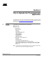
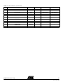
AVR Butterfly Evaluation Kit
..............................................................................................
User Guide
Table of Contents
Section 1
Introduction ........................................................................................... 1-5
1.1
Resources Available on the AVR Butterfly Kit ..........................................1-6
Section 2
How to Operate the Pre-programmed Application................................ 1-7
2.1
2.2
2.3
2.4
Included Firmware ....................................................................................1-7
Joystick Input ............................................................................................1-8
Menu System ............................................................................................1-9
Bootloader...............................................................................................1-11
Section 3
Using the AVR Butterfly ...................................................................... 1-15
3.1
3.2
3.3
3.4
3.5
3.6
3.7
3.8
3.9
3.10
3.11
Connectors..............................................................................................1-15
Programming the AVR Butterfly ..............................................................1-15
JTAG .......................................................................................................1-19
LCD Display ............................................................................................1-20
Joystick ...................................................................................................1-20
Sensors...................................................................................................1-21
Connect to PC.........................................................................................1-23
USI ..........................................................................................................1-24
External DataFlash .................................................................................1-25
Piezo element .........................................................................................1-26
Battery.....................................................................................................1-26
Section 4
Troubleshooting Guide ....................................................................... 1-27
Section 5
Technical Specifications ..................................................................... 1-29
Section 6
Technical Support............................................................................... 1-31
Section 7
Schematics ......................................................................................... 1-33
7.1
iii
4271C–AVR–04/05
Bill of Materials........................................................................................1-40
AVR Butterfly User Guide
-iv
4271C–AVR–04/05
AVR Butterfly User Guide
Section 1
Introduction
The AVR Butterfly evaluation kit is designed to demonstrate the benefits and key features of the AVR microcontrollers. It is a stand alone microprocessor module that can be
used in numerous applications:
! The AVR architecture in general and the ATmega169 in particular
! Low power design
! The MLF package type
! Peripherals
– LCD controller
– Memories
- Flash, EEPROM, SRAM, external DataFlash
– Communication interfaces
- UART, SPI, USI
– Programming methods
- Selfprogramming/ Bootloader, SPI, Parallel, JTAG
– Analog to Digital Converter (ADC)
– Timers/Counters
- Real Time Clock (RTC)
- Pulse Width Modulation (PWM)
It also serve as a development kit for the ATmega169, and can be used as a module in
other products.
Figure 1-1. AVR Butterfly
AVR Butterfly User Guide
-5
4271C–AVR–04/05
1.1
Resources
The following resources are available on the Butterfly kit.
Available on the ! ATmega169 (MLF-package)
AVR Butterfly Kit
! LCD-on-glass display with 120 segments, for demonstrating the ATmega169 LCD
controller.
! Joystick, 4-directions with centre push, as user input
! Piezo element, to play sounds
! 32kHz Xtal for the RTC
! 4 Mbit DataFlash, for data storage
! RS-232 level-converter, for communicating with off-board units
! Negative Temperature Coefficient (NTC) thermistor, to measure temperature
! Light Dependent Resistor (LDR), to measure light intenisty
! 3V button cell battery (600mAh) to provide operating power
! JTAG emulation, for debugging
! USI-interface, for additional communication interface
! Supported by AVR Studio 4.
! Pre-programmed with a demonstration application, including bootloader
! No external hardware is required to reprogram the AVR Butterfly
The ATmega169 in the kit controls the external peripherals, and can also be used to do
voltage readings from 0 to 5 volts. The kit can be reprogrammed a number of different
ways including serial programming through the JTAG port. Most users will prefer to use
the preloaded bootloader with AVR Studio to download new code.
For more information about the ATmega169, see the datasheet at www.atmel.com.
-6
4271C–AVR–04/05
AVR Butterfly User Guide
Section 2
How to Operate the Pre-programmed
Application
The AVR Butterfly comes with a preprogrammed application. This section will go
through the basics of this application. The firmware can be downloaded from the AVR
Butterfly web-site, http://www.atmel.com/products/AVR/butterfly.
2.1
Included
Firmware
These modules are preprogrammed with the AVR Butterfly:
! Bootloader code
! Application code
– State machine
– Features included
- Name-tag
- Clock (date)
- Temperature measurements
- Light measurements
- Voltage readings
- Play tunes/melodies
- Auto power save
- Adjust LCD contrast
– More functions can be added later on
- Calculator
- Reminder function
- Alarm (daily alarms, kitchen timers, etc…)
- Play melodies and displaying the text (Karaoke-function)
- With the 4Mbit dataflash one can store large amount of data. (Some
examples: AVR Info Bank (Basic of all AVR-parts); your local bus-table;
melodies, etc.)
Note:
AVR Butterfly User Guide
The application can be upgraded without any external hardware, due to the integrated level-converter and the Self-programming feature.
-7
4271C–AVR–04/05
2.2
Joystick Input
To operate the AVR Butterfly a joystick is used as user input. It operates in five directions, including center-push, see Figure 2-1.
Figure 2-1. Joystick Input
Using the joystick one can move around in the menu shown in Figure 2-2, and edit values, entering name, etc. Here are examples on how to enter your name.
2.2.1
Entering Your Name
Using the Joystick:
1. Press the joystick up (“SCROLL UP”) to wake the AVR Butterfly. If “AVR BUTTERFLY” is notscrolling over the display, press the joystick to the left (“EXIT
SUB-MENU”) until it does.
2. Press the joystick down (“SCROLL DOWN”) three times, so the string “NAME” is
displayed.
3. Press the joystick to the right (“ENTER SUB-MENU”). If this is the first time a
name is entered, the string “ENTER NAME” will be displayed, otherwise the
name already entered will be displayed and you have to press the joystick to the
right (“ENTER SUB-MENU”) once more.
4. When “ENTER NAME” is displayed press center push (“ENTER”). If this is the
first time you enter a name, the character “A” should be blinking in the right side
in the display, otherwise the last character of the already entered name will blink.
5. Press the joystick up (“SCROLL UP”) or down (“SCROLL DOWN”) to get to the
wanted character. Press the joystick to the right (“ENTER SUB-MENU”) to add a
new character or press the joystick to the left (“EXIT SUB-MENU”) to remove a
character.
6. When you have got all the characters, up to maximum 25, press center push
(“ENTER”) to save this name. The name will now be displayed in the display. If
the name is more than 6 characters long it will scroll over the display, otherwise it
will be displayed static.
-8
4271C–AVR–04/05
AVR Butterfly User Guide
2.2.2
Entering Your Name
Using a Terminal:
1. Connect a serial cable from the PC to the AVR Butterfly as described in Section
3.7 “Connect to PC”, Open a terminal on your PC (e.g. HyperTerminal) and configure the terminal to 19200 Baudrate, 8 Databits, none Parity and one stop bit.
2. Go through point 1, 2 and 3 above.
3. When the “ENTER NAME” is displayed press the joystick down (“SCROLL
DOWN”), and “DOWNLOAD NAME” will be displayed
4. Press center push (“ENTER”) to activate the UART, and the text “WAITING FOR
INPUT ON RS232” will be displayed.
5. Type your name in the terminal window on the PC (up to 25 characters) and save
the name by pressing enter on your PC-keyboard. The name you typed should
now be displayed in the AVR Butterfly display.
Note:
2.3
Menu System
AVR Butterfly User Guide
The Auto Power Off feature is default enabled. It will turn off the LCD after
default 30 minutes. This timeout can be changed or turned off. To wake the
AVR Butterfly from SLEEP, press the joystick in the UP-position.
A menu system is established to be able to shift between the different modules in application in a efficient way.
-9
4271C–AVR–04/05
Figure 2-2. Application Menu
-10
4271C–AVR–04/05
AVR Butterfly User Guide
Figure 2-2 shows the menu system of the application that comes with the AVR Butterfly.
The column to the left displays the main menu: “AVR Butterfly”, “Time”, “Music” etc… To
shift between the alternatives in the menu, press the joystick UP or DOWN. To enter a
sub-menu, press the joystick to the RIGHT. To exit a sub-menu, press the joystick to the
LEFT. To enter/adjust a value, press ENTER. E.g. when “Adjust clock” appears in the
LCD, press ENTER to enter the adjust function.
2.4
Bootloader
The AVR Butterfly comes with a bootloader which uses the self-programming feature in
the ATmega169. The bootloader combined with the integrated RS-232 level-converter
makes it possible to upgrade the application without any external hardware. It is based
on the Application Note AVR109: Self Programming AVR, but uses the new buffer load
mode for more efficient data downloading. AVR Prog, which is included in AVR Studio4,
is used as PC frontend. The data is transmitted through the RS-232 interface. Connect a
serial-cable from the PC to the AVR Butterfly as described in Section 3.7 “Connect to
PC”.
Figure 2-3. AVR Prog in AVRStudio4
2.4.1
Upgrade the
ATmega169
AVR Butterfly User Guide
A jump to the boot section can be done from the application, “Options>Bootloader>Jump to Bootloader”, see Figure 2-2, or just reset the ATmega169 by shortcut
pin 5 and 6 on J403 the ISP connector, (after a reset the ATmega169 will start in the
boot section). See Figure 3-3 for the pinout of the ISP-connector. Nothing will be displayed on the LCD while in boot section. Press and hold the joystick in the ENTERmodus while starting AVR Prog. When AVR Prog starts, release the joystick. Find the
*.hex file you want to program with the “Browse” button, and press “Program”. See that
“Erasing Device”, “Programing” and “Verifying” goes “OK”, this is done automatically.
After upgrading the application, press the “Exit”-button in AVR Prog in order to leave
programming mode in the ATmega169 bootloader.
-11
4271C–AVR–04/05
Figure 2-4. AVR Prog
2.4.2
Jump to the
Application Sector
From the Boot Section a jump to the application is done by pressing the joystick in the
UP-position.
2.4.3
Fuses and Lock Bits
For the firmware to operate correctly these fuses and lock bits on the ATmega169 are
the only ones to be programmed:
Extended Fuse Byte (0xFF)
– None
Fuse High Byte (0x98)
– JTAGEN (JTAG Interface Enabled)
– SPIEN (Serial Programming Enable)
– BOOTSZ1 (1024 words Boot Size)
– BOOTSZ0
– BOOTRST (Boot Reset vector Enabled)
-12
4271C–AVR–04/05
AVR Butterfly User Guide
Fuse Low Byte (0xE2)
– SUT0 (65 ms Start-up Time)
– CKSEL3 (Internal RC Oscillator)
– CKSEL2
– CKSEL0
Lock Bit Byte (0xEF)
– BLB11 (SPM is not allowed to write to the Boot Loader section)
Note:
AVR Butterfly User Guide
For all fuses and lock bits, “1” means unprogrammed and “0” means programmed.Using the AVR Butterfly
-13
4271C–AVR–04/05
-14
4271C–AVR–04/05
AVR Butterfly User Guide
Section 3
Using the AVR Butterfly
This section describes in detail how to use the AVR Butterfly evaluation kit.
3.1
Connectors
Some of the I/O-pins on the ATmega169 are available on the connectors of the AVR
Butterfly. These connectors are for communication, programming and input to the ADC
of the ATmega169.
Figure 3-1. Connectors
3.2
Programming the In addition to using the pre-programmed bootloader with AVR Studio, the ATmega169
on the AVR Butterfly can be programmed using SPI, High-voltage Parallel Programming
AVR Butterfly
and the JTAG interface.
3.2.1
In-System
Programming
AVR Butterfly User Guide
-15
4271C–AVR–04/05
Figure 3-2. In-System Programming
To program the ATmega169 using ISP Programming mode, connect a 6-wire cable
between the ISP6PIN connector on the STK500 board and J403 the ISP connector on
the AVR Butterfly as shown in Figure 3-2. This device can be programmed using the
Serial Programming mode in the AVR Studio4 STK500 software. Instead of soldering in
a ISP-header, one can make contact just by pressing the header to the footprint. Make
sure that pin 1 on the STK500 match with pin 1 on the AVR Butterfly. See Figure 3-3 for
the pinout of the ISP Connector.
Figure 3-3. ISP Connector, J403
1 2
PB3
VCC_EXT
PB1
PB2
RST
GND
ISP
Notes: 1. More information about the STK500 can be found in the STK500 User
Guide, which is available at the Atmel web site, www.atmel.com. See
STK500 User Guide for information on how to use the STK500 front-end
software for ISP Programming.
2. Do not use the AVRISP for In-System Programming, unless if the kit is powered from an external power source.
-16
4271C–AVR–04/05
AVR Butterfly User Guide
3.2.2
High-voltage Parallel
Programming
It is possible to program the ATmega169 through the High-voltage Parallel Programming interface. However this requires to move two resistors on the PCB. High-voltage
Parallel Programming is only meant to be used in the worst case scenario, where both
SPI and the JTAG interface are disabled.
To make the parallel programming work, R203 must be placed where the R204 should
be, and R404 must be placed where the R403 should be according to Figure 3-4. See
the Assembly Drawing in the 7 Complete Schematics
Figure 3-4. Ohm Resistors
Connect RESET, BSEL2 and XTAL1 from the STK500 to respectively pin 6, pin 8 and
pin 10 on the JTAG (J402) connector on the AVR Butterfly. See Figure 3-5. The JTAG
connector must be mounted on the back side of the AVR Butterfly.
Figure 3-5. Reset, BSEL2 and XTAL1 cables
Connect PROG DATA and PROG CTRL from the STK500 to respectively PORTB and
PORTD on the AVR Butterfly. Make sure that pin 1 on the STK500 connects to pin 1 on
the AVR Butterfly.
AVR Butterfly User Guide
-17
4271C–AVR–04/05
Figure 3-6. PORTB and PORTD
See the Schematic and the Assembly Drawing in the 7 Complete Schematics for further
details.
The device can now be programmed using the High-voltage Programming mode in AVR
Studio STK500 software.
During programming there will be some noise from the piezo element, and some flickering on the LCD, this because PORTB and PORTD are connected to theses modules.
Figure 3-7 shows the pinout for the I/O port headers PORT B and PORT D.
Figure 3-7. PORT B and PORT D
1 2
1 2
PB1
PD0
PD1
PB2
PB3
PD2
PD3
PB4
PB5
PD4
PD5
PB6
PB7
PD6
PD7
PB0
GND
VCC_EXT
PORTB
Note:
-18
4271C–AVR–04/05
GND
VCC_EXT
PORTD
When the AVR Butterfly is configured in High-voltage Parallel Programming
mode, the JTAG interface will not work, neither will the external crystal, causing
the pre-programmed application that comes with the AVR Butterfly to not operate correctly.
AVR Butterfly User Guide
Note:
3.3
JTAG
More information about the STK500 can be found in the STK500 User Guide,
which is available at the Atmel web site, www.atmel.com. See the STK500 User
Guide for information on how to use the STK500 front-end software in High-voltage Programming mode.
Figure 3-8 shows how to connect the JTAG ICE probe to the AVR Butterfly.
Figure 3-8. JTAG connector
Note:
The JTAG connector must be mounted on the back-side of the AVR Butterfly.
The JTAG connector is used for the ATmega169 built in JTAG interface. The pinout of
the connector is shown in Figure 3-9 and is compliant with the pin out of the JTAG ICE
available from Atmel. Connecting a JTAG ICE to this connector allows On-chip Debugging of the ATmega169.
More information about the JTAG ICE and the On-chip Debugging can be found in the
AVR JTAG ICE User Guide, which is available at the Atmel web site, www.atmel.com.
Note: Pin 7, NC(VCC) is the Vsupply pin for the JTAG. This pin is not connected
because the JTAG would draw power from the battery on the AVR Butterfly.
Pin 8, NC(BS2) and the pin 10, GND(XTAL1) can be modified serve as the BS2 and
XTAL1 pin during High-voltage Parallel Programming. For more details see 3.2.2 Highvoltage Parallel Programming.
Figure 3-9. JTAG Connector
1 2
TCK
GND
TDO
VCC
TMS
RST
NC(VCC)
NC(BS2)
GND(XTAL1)
TDI
JTAG
Note:
AVR Butterfly User Guide
It is highly recommended to apply external power (3,1 – 4,5V), when using the
JTAG to save the battery. See Figure 3-10 for how to connect external power.
-19
4271C–AVR–04/05
Make sure to disable the OCD-fuse after a debugging session, due to power
consumption. The OCD-fuse will be disabled if pressing on the “Stop Debugging” button in AvrStudio4, before disconnecting the JTAG ICE probe from the
AVR Butterfly.
Figure 3-10. External Power
External power can be applied at pin 9 and 10 at both PORTB and PORTD, see Figure
3-7 for the pinout.
If the JTAG are not in use, the four JTAG pins can be used as input for the ADC channels ADC[4:7]. See the ATmega169 datasheet for more information, available from
www.atmel.com
3.4
LCD Display
The LCD display on the AVR Butterfly is the same as used on the STK502 available
from Atmel. The connections between the ATmega169 and the LCD are also the same.
See the STK502 User Guide at www.atmel.com for more information about the LCD display, and the LCD bit-mapping.
For more information on how to write software for the LCD-display see application note
“AVR064: STK502 – A Temperature Monitoring System with LCD Output” and application note “AVR065: LCD Driver for the STK502 LCD”.
Note: Touching the LCD-pins will affect the segments on the LCD.
3.5
Joystick
-20
4271C–AVR–04/05
The AVR Butterfly has a miniature joystick for input from user. It operates in five directions, including centre-push. The common line of all directions is GND. This means that
internal pull-up must be enabled on the ATmega169 to detect the input from the joystick.
AVR Butterfly User Guide
Figure 3-11. Joystick Schematic
3.6
Sensors
The AVR Butterfly has two on-board sensors which makes it possible to measure both
temperature and light. In addition is has a voltage-divider that is used to measure voltages from 0 to 5V.
3.6.1
Temperature Sensor
The temperature sensor can be found at the back side of the AVR Butterfly. See Figure
3-12.
AVR Butterfly User Guide
-21
4271C–AVR–04/05
Figure 3-12. Temperature Sensor
An NTC (Negative Temperature Coefficient)-thermistor is used to measure the temperature. An NTC-thermistor is characterised by the fact that when the temperature goes
down the resistance goes up. Using a voltage divider and reading the voltage over the
thermistor through the ADC-channels on the ATmega169, the temperature in can be
calculated. Equation for calculating the temperature in Celsius is shown in Figure 3-13.
Figure 3-13. Temperature Equation
β
Temperature = --------------------------------------------------------------------------- – Tzero
ADC
β -⎞
⎛ ln ⎛ ------------------------------------⎞ + ------------⎝ ⎝ ( 1024 – ADC )⎠ Tamb⎠
β
= 4250
ADC = Value in the ATmega169 ADC Data Register – ADCL and ADCH
Tzero = 273°K
Tamb = 298°K (273° + 25°)
The temperature in Fahrenheit can be found from Figure 3-14
Figure 3-14. Fahrenheit VS Celsius
F – 32 )⎞
⎛ (-------------------- = C
⎝ 1.8 ⎠
The AVR Butterfly is capable of measuring the temperature from –10ºC/+14ºF to
+60ºC/140ºC with an accuracy of ±1ºC.
-22
4271C–AVR–04/05
AVR Butterfly User Guide
3.6.2
Light Sensor
The light sensor is located at the front of the AVR Butterfly, over the LCD. See Figure
3-15.
Figure 3-15. Light Sensor
An LDR (Light Dependent Resistor) is used to measure the light. An LDR is characterised by the fact that when the light decreases the resistance goes up. Using a voltage
divider and reading the voltage over the LDR through the ADC-channels on the
ATmega169, the light can be calculated.
3.6.3
Voltage Reader
The AVR Butterfly is capable of reading voltages from 0V to 5V. The input must be connected to the pins shown in Figure 3-16. Using a voltage divider and reading the voltage
over the resistors through the ADC-channels on the ATmega169, the applied voltage
can be calculated. The accuracy is about 0,1V.
Figure 3-16. Voltage Readings
Note:
3.7
Connect to PC
AVR Butterfly User Guide
Do not apply voltages above maximum 10V
The AVR Butterfly has an on-board level-converter for the RS-232 interface. This means
that no external hardware is required to reprogram the AVR Butterfly using the self programming feature in the ATmega169. Figure 3-17 shows how to connect a serial-cable
to the AVR Butterfly. The integrated RS232 level converter operates down to 2.0V supply voltage.
-23
4271C–AVR–04/05
Table 3-1. UART
AVR Butterfly UART
COM2
Pin 1 (RXD)
Pin 3
Pin 2 (TXD)
Pin 2
Pin 3 (GND)
Pin 5
Figure 3-17. UART Connector
3.8
USI
The AVR Butterfly has connections for the USI-interface. Figure 3-18 shows the pin-out
for the USI. Through the USI interface other modules can be connected, and the AVR
Butterfly can serve as a top-module card.
Figure 3-18. USI Connector
-24
4271C–AVR–04/05
AVR Butterfly User Guide
Table 3-2. USI
AVR Butterfly USI
Pin 1 (USCK/SCL)
Pin 2 (DI/SDA)
Pin 3 (DO)
Pin 4 (GND)
3.9
External
DataFlash
An external dataflash is provided with the AVR Butterfly. This is the 4-megabit serial
DataFlash from Atmel, type AT45DB041B. More information about the DataFlash can
be found in the datasheet available at the Atmel web site:
http://www.atmel.com/products/DataFlash/
The DataFlash is connected to the SPI interface. This means that in addition to communicate with the ATmega169 on the AVR Butterfly, it can also be accessed externally
through the ISP connector.
Note: If the DataFlash is to be accessed externally, the ATmega169 on the AVR Butterfly must be set to disable its own SPI interface to avoid contention on the
interface.
Figure 3-19. DataFlash
Figure 3-20. DataFlash Schematic
AVR Butterfly User Guide
-25
4271C–AVR–04/05
3.10
Piezo element
A piezo element is used to be able to play sounds on the AVR Butterfly. The piezo is
connected to PORTB5 on the ATmega169. And using the PWM, one can get the different frequencies required to play tunes.
Figure 3-21. Piezo Element
3.11
Battery
Model: CR2450
Nominal Voltage: 3.0 Volts
Nominal Capacity: 550 mAh (@0.2 mA Discharge Current, +23ºC)
Standard Discharge Current 0.2 mAh
Maximum recommended current under continuous discharge: 3 mA
Maximum recommended current under pulse discharge: 15 mA
Note: DO NOT recharge, short-circuit, disassemble, deform, heat or place the battery
near a direct flame. This battery containsflammable materials such as lithium
and organic solvent and performing any of the above actions could cause it to
ignite explode or become damaged.
The battery is protected by a schottky diode, this will prevent recharging of the battery if
external power is applied to PORTB or PORTD on the AVR Butterfly.
-26
4271C–AVR–04/05
AVR Butterfly User Guide
Section 4
Troubleshooting Guide
Table 4-1. Troubleshooting Guide
Problem
Reason
Solution
The LCD is not enabled in the AVR device.
Check the LCD initialization. (1)
The update frequency is not correct.
Verify that the clock prescaling correspond
with the clock-source. (1)
Your fingers are touching the LCD pins or
PORTD
Hold the AVR Butterfly on the edge of the
PCB, without touching the LCD pins
ISP cable not connected properly to the
ISP-footprint
Connect the ISP cable according to Figure
3-2
STK500 target voltage error.
Please refer to the ATmega169 datasheet
for the Serial Programming Voltage limits.
Adjust the target voltage on the STK500
board accordingly.
Cables not connected properly
Please refer to Section 3.2.2 “High-voltage
Parallel Programming” for correct parallel
programming set-up.
STK500 target voltage error.
Please refer to the ATmega169 datasheet
for the Parallel Programming Voltage
limits. Adjust the target voltage on the
STK500 board accordingly.
Nothing is displayed on the LCD.
Some segments on the LCD seems to
disappear
Serial Programming does not work
Parallel programming does not work
Notes: 1. See the Application Note “AVR065 LCD driver for the STK502 LCD” on how
to control the LCD-display, or the Application Note “AVR064 STK502 – A
temperature monitoring system with LCD output” Or program the application that comes with the AVR Butterfly
AVR Butterfly User Guide
-27
4271C–AVR–04/05
-28
4271C–AVR–04/05
AVR Butterfly User Guide
Section 5
Technical Specifications
System Unit
Physical Dimension ………………………………................................…45 x 67 x 14 mm
Weight...………………………………………………………………..............................28 g
Operation Conditions
Temperature…………………………………………………..........................…...0ºC - 50ºC
If using external power……………………………………...........................……3,1V - 4,5V
Temperature measurement accuracy……………………………….......................…..±1ºC
Voltage reading accuracy…………………………………………..........................….±0,1V
AVR Butterfly User Guide
-29
4271C–AVR–04/05
-30
4271C–AVR–04/05
AVR Butterfly User Guide
Section 6
Technical Support
For Technical support, please contact [email protected]. When requesting technical support, please include the following information:
! Which target AVR device is used (complete part number)
! Target voltage and speed
! Clock source and fuse setting of the AVR
! Programming method
! Hardware revisions of the AVR tools, found on the PCB
! Version number of AVR Studio (This can be found in the AVR Studio help menu).
! PC operating system and version/build
! PC processor type and speed
! A detailed description of the problem
AVR Butterfly User Guide
-31
4271C–AVR–04/05
-32
4271C–AVR–04/05
AVR Butterfly User Guide
Section 7
Schematics
On the following pages the complete schematics and assembly drawing of the AVR Butterfly revision A are shown.
AVR Butterfly User Guide
-33
4271C–AVR–04/05
A
B
C
1
VCP
1
2
GND
GND
2
RESET
RESET
VCC
PF0
PF1
GND
C106
10N_50V_X7R
R100
10K
VCC
3
PB7
GND
VCC
1
2
3
4
5
6
7
8
9
10
11
12
13
14
15
16
LCDCAP
PE0(RXD)
PE1(TXD)
PE2(AIN0/XCK)
PE3(AIN1)
PE4(SCL/USCK)
PE5(SDA/DI)
PE6(DO)
PE7
PB0(SS)
PB1(SCK)
PB2(MOSI)
PB3(MISO)
PB4(OC0)
PB5(OC1A)
PB6(OC1B)
GND
C103
100N_16V_X7R
GND
LCDCAP
PE0
PE1
PE2
PE3
PE4
PE5
PE6
PE7
PB0
PB1
PB2
PB3
PB4
PB5
PB6
2
BLM-21A102S
L100
PB[7..0] PB[7..0]
RST_FLASH
PE2
AVR_RxD
GND
1
(temperature sensor)
(voltage reader)
C105
1U_16V_X7R
Sensor_2
C102
100N_16V_X7R
PE[6..4] PE[6..4]
PE3
AVR_TxD
VCP
C101
100N_16V_X7R
1
2
PF[7..4]
1
2
PF[7..4]
2
1
3
PF0
PF1
C104
100N_16V_X7R
LCD19
LCD17
2
1
2
1
2
1
2
4
1
2
(COM3)PA3
(SEG0)PA4
(SEG1)PA5
(SEG2)PA6
(SEG3)PA7
(SEG4)PG2
(SEG5)PC7
(SEG6)PC6
(SEG7)PC5
(SEG8)PC4
(SEG9)PC3
(SEG10)PC2
(SEG11)PC1
(SEG12)PC0
(SEG13)PG1
(SEG14)PG0
PF4
PF5
PF6
PF7
4
VCC
GND
COM3
LCD27
LCD28
LCD29
LCD4
LCD6
LCD25
LCD26
LCD5
LCD8
LCD22
LCD23
LCD7
LCD10
LCD20
LCD21
5
5
ATMEGA169V-1MC
48
47
46
45
44
43
42
41
40
39
38
37
36
35
34
33
U100
C100
100N_16V_X7R
COM0
COM1
COM2
64
63
62
61
60
59
58
57
56
55
54
53
52
51
50
49
AVCC
AGND
AREF
(ADC0)PF0
(ADC1)PF1
(ADC2)PF2
(ADC3)PF3
(TCK/ADC4)PF4
(TMS/ADC5)PF5
(TDO/ADC6)PF6
(TDI/ADC7)PF7
GND
VCC
(COM0)PA0
(COM1)PA1
(COM2)PA2
PB7(OC2)
PG3(T1/SEG24)
PG4(T0/SEG23)
RESET
VCC
GND
XTAL2(TOSC2)
XTAL1(TOSC1)
PD0(ICP/SEG22)
PD1(INT0/SEG21)
PD2(SEG20)
PD3(SEG19)
PD4(SEG18)
PD5(SEG17)
PD6(SEG16)
PD7(SEG15)
4271C–AVR–04/05
17
18
19
20
21
22
23
24
25
26
27
28
29
30
31
32
-34
LCD15
LCD16
LCD18
LCD13
LCD11
LCD12
LCD14
LCD9
D
1
LCD[32..3]
COM[3..0]
TOSC2
TOSC1
LCD[32..3]
COM[3..0]
6
6
30-Apr-2003
MCU.Sch
7
TITLE: AVR Butterfly
Document number: A0301.3.1000.A
Date:
NORWAY
7075 TILLER
Vestre Rosten 79,
ATMEL Norway
7
09:34:10
1
8
Revision: A
PAGE:
8
of
4
A
B
C
D
Figure 7-1. Schematics, 1 of 4
AVR Butterfly User Guide
A
B
C
D
1
R208
100K
VCP
R205
100K
VCC
PB[7..0]
R206
100K
VCC
LCD[32..3]
2
1
2
3
4
5
6
7
8
9
10
11
12
13
14
15
16
17
3
4
SO
GND
VCC
WP
8 PB3
7
6
5
V_in
D200
BZX399-C1V8
GND
R209
300K
R212
1M5
AT45DB041B-SC-2.5
SI
SCK
RESET
CS
U201
Dataflash
H4042-DL
4
GND
LCD display
BP3
BP2
BP4
BP1
1K/1L/1M/6
1F/1G/1E/X2
2K/2J/2L/2M
1A/1J/1N/1D
3K/3J/3L/3M
X1/1B/1C/S6
3A/3B/3C/3D
1/2F/2E/2P
4K/4J/4L/4M
S1/2H/2G/2N
4A/4B/4C/4D
2A/2B/2C/2D
5K/5J/5L/5M
2/3F/3E/3P
5A/5B/5C/5D
S2/3H/3G/3N
9/6F/6E/6P
3/COL1/S7/7
S9/6H/6G/6N
S3/4F/4E/4P
6K/6J/6L/6M
4/4H/4G/4N
6A/6B/6C/6D
S4/5F/5E/5P
10/7F/7E/7P
5/5H/5G/5N
S10/7H/7G/7N
S5/COL2/S8/8
7K/7J/7L/7M
7A/7B/7C/7D
U200
Voltage reading
3
4
PB2 1
PB1 2
V_in
GND
PF1
PB0
LCD4
LCD5
LCD6
LCD7
LCD8
LCD9
LCD10
LCD11
LCD12
LCD13
LCD14
LCD15
LCD16
LCD17
COM2
COM3
GND
N egative Temperature R211
Coefficient (NTC)
NCP18WF104J03RB
resistor.
PF0
RST_FLASH
PB[7..0]
LCD[32..3]
COM[3..0]
3
0R
R200 2
Sensor_2
R207
100K
VCC
1
LCD29
LCD28
LCD27
LCD26
LCD25
LCD24
LCD23
LCD22
LCD21
LCD20
LCD19
LCD18
COM1
COM0
VCC
R210
3K3
VCP
GND
C200
100N_16V_X7R
Connects COL1 to
COL2 on the LCD
5
GND
5
R213
Light Dependent Resistor
NSL 19M51
34
33
32
31
30
29
28
27
26
25
24
23
22
21
20
19
18
1
2
COM[3..0]
1
2
1
2
6
Piezo element
6
VCC
KMT-1603
XC200
2
1
4
3
6
5
PB4
PB6
PB7
PE2
PE3
7
2
3
2
5-Mar-2003
Peripherals.Sch
7
TITLE: AVR Butterfly
P_XTAL1
PB5
2
8
8
Revision: A
PAGE:
TOSC2
TOSC1
P_XTAL1
PB[7..0]
PE3
PB[7..0]
11:01:58
R204
0R
NOT MOUNTED
R202 1
0R
PE2
PB[7..0]
Document number: A0301.3.1000.A
Date:
NORWAY
7075 TILLER
2
R203 1
0R
Vestre Rosten 79,
ATMEL Norway
IQD32.768KHZ
1
4
XC201
GND
R201
0R
BC847B
NOT MOUNTED
Q200
1
4 way joystick with GND
press function
SKRHABE010
Center
A
B
C
D
Common
SW200
3
2
1
2
2
1
2
1
1
2
2
2
1
1
2
1
2
1
2
1
1
2
AVR Butterfly User Guide
2
1
of
4
A
B
C
D
Figure 7-2. Schematics, 2 of 4
-35
4271C–AVR–04/05
A
B
C
1
TXD
RXD
2
AVR_RxD
AVR_TxD
GND
GND
0R
R302
2
0R
R303
2
3
R301
VC080514A300
1
R300
VC080514A300
1
3
BC847BPN
Q300A
2
R304
4,7K
VCC
2
1
6
1
4
4
1
2
GND
4,7K
R305
D300
BAT74
5
5
2
4,7K
R306
1
2
1
2
2
3
1
2
1
2
1
4
R307
4,7K
5
6
6
C300
1U_16V_X7R
R308
4,7K
Q300B
BC847BPN
VCC
4
3
1
2
4271C–AVR–04/05
1
-36
2
D
1
28-Jan-2003
RS232.Sch
7
TITLE: AVR Butterfly
Document number: A0301.3.1000.A
Date:
NORWAY
7075 TILLER
Vestre Rosten 79,
ATMEL Norway
7
12:34:59
PAGE:
3
8
Revision: A
8
of
4
A
B
C
D
Figure 7-3. Schematics, 3 of 4
AVR Butterfly User Guide
A
B
C
1
PF[7..4]
RESET
PB[7..0]
VCC_EXT
2
PF[7..4]
PB[7..0]
PF7
PF4
PF6
PF5
PB3
PB1
VCC
MOSI
GND
2
2
4
6
2
GND
PB2
1
3
5
7
9
2
4
6
8
10
RESET
VCC
GND
3
C403
100N_16V_X7R
JTAG
NOT MOUNTED
J402
2
GND
GND
R404
0R
2
COM0
P_XTAL1
0R
NOT MOUNTED
(BS2)1 R403
VCC
GND
GND
J404
KEY-3008-TR
C401
100N_16V_X7R
VCC_EXT
Batteryclip
0R
1 R401
R400
33R
NOT MOUNTED
3
VCC_EXT
1
Disable the Vsupply
to the JTAG
ISP_CONNECTOR
NOT MOUNTED
MISO
SCK
RESET
J403
D400
BAT54C
3
R402
0R
NOT MOUNTED
VCC
1
3
5
1
1
2
VCC
1
2
1
2
2
1
2
1
2
COM[3..0]
Coin Cell
BT400
Battery
CR-2450
4
P_XTAL1
These two pins are for
parallel programming
COM[3..0]
4
1
2
5
5
Voltage
reader
UART pins
USI
GND
GND
1
3
5
7
9
1
3
5
7
9
2 LCD16
4 LCD13
6 LCD12
8 LCD9
10
PE[6..4]
RXD
PE[6..4]
VCC_EXT
GND
6
LCD[32..3]
GND
C400
100N_16V_X7R
V_in
GND
7
19-Feb-2003
Connectors.Sch
7
TITLE: AVR Butterfly
Document number: A0301.3.1000.A
Date:
NORWAY
7075 TILLER
Vestre Rosten 79,
ATMEL Norway
V_in
TXD
C402
100N_16V_X7R
VCC_EXT
LCD[32..3]
VCC_EXT
PB[7..0]
VCC_EXT
PB[7..0]
(voltage reader)
GND
GND
PH_2,54_2 X 1
NOT MOUNTED
J407
1
2
PB1
PB3
PB5
PB7
PORTD
NOT MOUNTED
J401
PH_2,54_3 X 1
NOT MOUNTED
J406
1
2
3
2
4
6
8
10
PORTB
NOT MOUNTED
PH_2,54_4 X 1
NOT MOUNTED
J405
1 PE4
2 PE5
3 PE6
4
LCD15
LCD18
LCD11
LCD14
PB0
PB2
PB4
PB6
J400
6
1
2
1
AVR Butterfly User Guide
2
D
1
08:18:49
4
8
Revision: A
PAGE:
8
of
4
A
B
C
D
Figure 7-4. Schematics, 4 of 4
-37
4271C–AVR–04/05
Figure 7-5. Assembly Drawing, Top Side
-38
4271C–AVR–04/05
AVR Butterfly User Guide
Figure 7-6. Assembly Drawing, Back Side
AVR Butterfly User Guide
-39
4271C–AVR–04/05
7.1
Bill of Materials
Table 7-1. Bill Of Material_
Used
Part Type
Designator
Value
8
0R
R200 R201
0R
Manufacturer
Design specific
R202 R203
R302 R303
R401 R404
3
0R
R204 R402
0R
NOT MOUNTED
*
R403
1
1M5
R212
1M5
2
1U_16V_X7R
C105 C300
1u
1
3K3
R210
3k3
*
5
4,7K
R304 R305
4k7
*
MURATA
*
R306 R307
R308
1
10K
R100
10k
*
1
10N_50V_X7R
C106
10n
*
1
33R
R400
33R
NOT MOUNTED
4
100K
R205 R206
100k
*
100n
*
*
R207 R208
10
100N_16V_X7R
C100 C101
C102 C103
C104 C200
C400 C401
C402 C403
1
300K
R209
300K
1
AT45DB041B-SC-2.5
U201
4Mb
1
ATMEGA169V-1MC
U100
1
AVR BUTTERFLY A0301.3.1000.A
PCB500
1
BAT54C
D400
PHILIPS
*
1
BAT74
D300
PHILIPS
*
1
BC847B
Q200
PHILIPS
NOT MOUNTED
1
BC847BPN
Q300
PHILIPS
*
1
BLM-21A102S
L100
MUR
*
1
BZX399-C1V8
D200
PHILIPS
*
1
CR-2450
BT400
MAXELL
*
1
H4042-DL
U200
1
IQD32.768KHZ
XC201
1
ISP_CONNECTOR
1
KEY-3008-TR
-40
4271C–AVR–04/05
ATMEL
*
ATMEL
*
*
3V
*
32,768kHz
IQD Crystals
*
J403
SCOTT ELECT.
NOT MOUNTED
J404
KEYSTONE
*
AVR Butterfly User Guide
Table 7-1. Bill Of Material_(Continued)
Used
Part Type
Designator
Value
Manufacturer
Design specific
1
NCP18WF104J03RB
R211
100K
MURATA
*
1
NSL 19M51
R213
SILONEX
*
1
PH_2,54_2 X 1
J407
SCOTT ELECT.
NOT MOUNTED
1
PH_2,54_3 X 1
J406
SCOTT ELECT.
NOT MOUNTED
1
PH_2,54_4 X 1
J405
SCOTT ELECT.
NOT MOUNTED
3
PH_2,54_5 X 2
J400 J401
SCOTT ELECT.
NOT MOUNTED
J402
1
SKRHABE010
SW200
ALPS
*
1
KMT-1603
XC200
KINGSTATE
*
2
VC080514A300
R300 R301
1
U562246
M500
AVR Butterfly User Guide
*
-41
4271C–AVR–04/05
Atmel Corporation
2325 Orchard Parkway
San Jose, CA 95131, USA
Tel: 1(408) 441-0311
Fax: 1(408) 487-2600
Regional Headquarters
Europe
Atmel Sarl
Route des Arsenaux 41
Case Postale 80
CH-1705 Fribourg
Switzerland
Tel: (41) 26-426-5555
Fax: (41) 26-426-5500
Asia
Room 1219
Chinachem Golden Plaza
77 Mody Road Tsimshatsui
East Kowloon
Hong Kong
Tel: (852) 2721-9778
Fax: (852) 2722-1369
Japan
9F, Tonetsu Shinkawa Bldg.
1-24-8 Shinkawa
Chuo-ku, Tokyo 104-0033
Japan
Tel: (81) 3-3523-3551
Fax: (81) 3-3523-7581
Atmel Operations
Memory
2325 Orchard Parkway
San Jose, CA 95131, USA
Tel: 1(408) 441-0311
Fax: 1(408) 436-4314
RF/Automotive
Theresienstrasse 2
Postfach 3535
74025 Heilbronn, Germany
Tel: (49) 71-31-67-0
Fax: (49) 71-31-67-2340
Microcontrollers
2325 Orchard Parkway
San Jose, CA 95131, USA
Tel: 1(408) 441-0311
Fax: 1(408) 436-4314
La Chantrerie
BP 70602
44306 Nantes Cedex 3, France
Tel: (33) 2-40-18-18-18
Fax: (33) 2-40-18-19-60
ASIC/ASSP/Smart Cards
1150 East Cheyenne Mtn. Blvd.
Colorado Springs, CO 80906, USA
Tel: 1(719) 576-3300
Fax: 1(719) 540-1759
Biometrics/Imaging/Hi-Rel MPU/
High Speed Converters/RF Datacom
Avenue de Rochepleine
BP 123
38521 Saint-Egreve Cedex, France
Tel: (33) 4-76-58-30-00
Fax: (33) 4-76-58-34-80
Zone Industrielle
13106 Rousset Cedex, France
Tel: (33) 4-42-53-60-00
Fax: (33) 4-42-53-60-01
1150 East Cheyenne Mtn. Blvd.
Colorado Springs, CO 80906, USA
Tel: 1(719) 576-3300
Fax: 1(719) 540-1759
Scottish Enterprise Technology Park
Maxwell Building
East Kilbride G75 0QR, Scotland
Tel: (44) 1355-803-000
Fax: (44) 1355-242-743
Literature Requests
www.atmel.com/literature
Disclaimer: The information in this document is provided in connection with Atmel products. No license, express or implied, by estoppel or otherwise, to any
intellectual property right is granted by this document or in connection with the sale of Atmel products. EXCEPT AS SET FORTH IN ATMEL’S TERMS AND CONDITIONS OF SALE LOCATED ON ATMEL’S WEB SITE, ATMEL ASSUMES NO LIABILITY WHATSOEVER AND DISCLAIMS ANY EXPRESS, IMPLIED OR STATUTORY
WARRANTY RELATING TO ITS PRODUCTS INCLUDING, BUT NOT LIMITED TO, THE IMPLIED WARRANTY OF MERCHANTABILITY, FITNESS FOR A PARTICULAR
PURPOSE, OR NON-INFRINGEMENT. IN NO EVENT SHALL ATMEL BE LIABLE FOR ANY DIRECT, INDIRECT, CONSEQUENTIAL, PUNITIVE, SPECIAL OR INCIDENTAL DAMAGES (INCLUDING, WITHOUT LIMITATION, DAMAGES FOR LOSS OF PROFITS, BUSINESS INTERRUPTION, OR LOSS OF INFORMATION) ARISING OUT
OF THE USE OR INABILITY TO USE THIS DOCUMENT, EVEN IF ATMEL HAS BEEN ADVISED OF THE POSSIBILITY OF SUCH DAMAGES. Atmel makes no
representations or warranties with respect to the accuracy or completeness of the contents of this document and reserves the right to make changes to specifications
and product descriptions at any time without notice. Atmel does not make any commitment to update the information contained herein. Atmel’s products are not
intended, authorized, or warranted for use as components in applications intended to support or sustain life.
© Atmel Corporation 2005. All rights reserved. Atmel ®, logo and combinations thereof, AVR ®, and AVR Studio ® are registered trademarks,
and Everywhere You Are SM are the trademarks of Atmel Corporation or its subsidiaries. Microsoft ®, Windows ®, Windows NT®, and Windows XP ®
are the registered trademarks of Microsoft Corporation. Other terms and product names may be trademarks of others.
Printed on recycled paper.
4271C–AVR–04/05