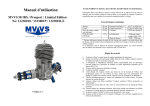
1
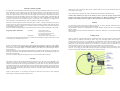
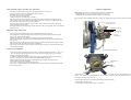
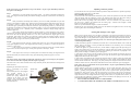
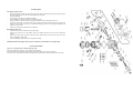
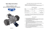
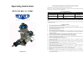
Operating instructions
Before using the engine, please read these instructions carefully.
Congratulations on choosing the gas engine MVVS 58 liquid cooled (LC).
MVVS 58 LC has been designed and manufactured for propeller-powered radio-controlled model planes
especially for those where is air cooling complicated.
MVVS 58 IRS / LC #3002
Technical specifications
Bore
Stroke
Weight of complete
engine without ignition *
42 mm
42 mm
Maximum power output**
Maximální torque**
8,5 HP / 6950 RpM
8,8 N/m / 6600 RpM
Unleaded fuel
1830 g
Fuel
95 octane
Oil with petrol in
Weight of ignition unit
165 g
Lubrication
mixture 1:40
RpM range
1000 – 7500 RpM
* Some manufacturers state the weight of incomplete engines. The value in the table above stands for the
weight of a completely assembled engine, including the spark plug, carburetor, drive washer and prop
screws.
** Power output varies with the exhaust used. The value given in the table stands for the maximum
available power output.
Safety precautions
1)
2)
3)
4)
5)
6)
7)
8)
9)
10)
11)
12)
13)
14)
15)
16)
17)
18)
19)
20)
Version 1.2
Never use the engine for any manned vehicles.
When operating model planes, always follow the rules and laws in effect in your country.
The manufacturer declines all responsibility for all damages arising from the operation of models and
other appliances droved by MVVS 58 engine.
Always use original spare parts.
Never tamper with the engine construction.
Before each flight check that all the propeller screws are tightened up and in good condition. If you
use a spinner, check that it is tightened up, too. When mounting the spinner always follow the
assembly instructions.
Periodically check that the engine is firmly fixed to the engine mounts. Never start a loose engine!
Always use a balanced propeller! Always replace the propeller when damaged!
Make sure that no part of your body intersects the plane of the spinning propeller.
Always wear close-fitting, well-fastened clothes when starting or operating the running engine. Never
wear loosely hanging clothes (ties, scarf, etc.).
Never try to stop the engine by any part of your body.
Always stop the engine either by turning off the ignition switch or by completely closing the
carburetor throttle valve.
Before starting the engine make sure that the model is safely fixed in place and cannot start moving.
Fuel is combustible and therefore must be kept in an enclosed container at a safe distance from the
engine when it is running.
When preparing fuel carefully follow the manufacturer’s or dealer’s instructions.
Small objects must be kept at a safe distance from the engine when it is running. Never throw any
objects towards the spinning propeller.
Be careful in choosing the location where you wish to start the engine. Avoid dusty or sandy areas.
Start the engine in well-ventilated areas only. Never start the engine indoors.
When starting the engine make sure that bystanders, especially children, are at a safe distance of at
least 10 m.
The engine power output makes it possible to fly big models. Mal-operation of such models may
cause serious damage. Start using the MVVS 58 in model planes only after you have mastered
operating smaller models.
Selecting a suitable propeller
It is usually the case that propellers of the same dimensions coming from different manufacturers are not the
same. Oftentimes not even propellers of the same dimensions produced by a same manufacturer are not the
same. The engine power is best utilized when the propeller dynamics curve and engine power curve
(revolutions / power output) intersect in the area of the engine top power output. Unfortunately, no propeller
manufacturer provides this information. Engine power output is also a variable quality. It depends above all
on the silencer used and can considerably vary. The situation is further complicated by environmental
parameters (temperature and atmospheric pressure in particular): low temperature and high pressure
increase propellers’ input requirements by 20% in comparison with input at hot weather.
MVVS 58 has been designed to generate maximum power at 6800 – 7100 RpM, according to the type of
exhaust used. If you wish to utilize the maximum power output, choose a propeller, which allow the engine
to reach these revolutions, or slightly lower revolutions (given the unloading of the propeller depending on
the speed of flight) on the ground.
We do not recommend using propellers with which the engine reaches more than 7500 RpM on the ground.
Suggested propeller dimensions:
two-blade:
22x10, 22x12, 22x14
24x8, 24x9, 24x10, 24x12
25x7, 25x8, 25x9, 25x10, 25x12
26x7, 26x8, 26x9, 26x10
three-blade
22x10, 22x12, 24x9, 24x10, 24x12
These values are only approximate and may vary with the factors described in the previous section, as well
as with the type of the exhaust system used.
Fuel
Always use unleaded 95-octane petrol mixed in the proportion 40 volume units of petrol to 1 unit of Mobil
Racing 2T oil. If necessary, quality brand-name synthetic oil intended for racing two-stroke engines
can be used too. Running the engine in, use MVVS Racing 2T oil which comes with the engine. Mix it in
the proportion 30:1.
Never use inexpensive oil developed for garden appliances or synthetic oils intended for the operation of
methanol model engines. The manufacturer declines all responsibility for all engine damages arising from
the use of low-quality fuel.
Store fuel in containers designed for this purpose. Do not use mixed fuel older than 90 days.
Assembly
The engine is fastened in place with four holders built in the rear cover. The rear cover is adjustable by 90°
which ensure easy access to the carburetor’s operating elements. The engine can be mounted directly to the
firewall or an assembly kit can be used (special accessories). Use M6 screws or screws M5 with a reduction
kit (special accessories). If you decide to fasten the engine using flexible motor mounts, always choose parts
with enough solidity and strength. Make sure to secure the screws against loosening and regularly check
that they are tightened up and in good condition. Position of carburetors difuzors should be placed at least
50mm from firewall.
Engine is water cooled so it is not necessary so intensive air flow under cowl. However some ventilating
around engine is needed to guarantee intake of cool air.
Ensure access of air to the engine intake as well. Caution: intake of warm air from beneath the cowl may
cut the engine power output.
Note: Attach a hose to the airpressure inlet on the carburetor and terminate it outside the cowl.
Caution! When mounting the engine in the model use seals to protect all openings and prevent the
pollution of the engine’s inside with sawdust, residual abrasives etc. Make sure that the inside of the
fuselage is clean and that all parts are tighten in place and cannot be sucked inside the engine.
Exhaust
Use only factory-made exhausts pipes designed for this type of engine, preferably brand-name MVVS
engines with which you also get the power output guaranteed.
The manufacturer declines all responsibility for all engine damages arising from the use of improper
exhaust systems.
When mounting the exhaust follow the manufacturer’s instructions. Make sure to secure sufficient cooling
of the exhaust.
Cooling system
Engine is cooled by water circulation between cylinder and cooler. Forced circulation is caused by dentil
pump powered by crankshaft (connected by elastic strap). This conception allows placing engine to
aircrafts where cooling by air is very complicated. It is recommended to use the same conception as shown
in picture below. It is necessary to purchase MVVS radiator kit (cat. no. 3370 – contains: cooler, hoses and
filling part) in order to make the engine work. In case that size of standard cooler is not suitable to your
needs it is possible to order size on you own request by your dealer or from producer directly.
Use distill water without any other addition in the cooling system. Empty the system when engine is out of
season. If you are going to store model with engine in place where might be frost always empty whole
system to avoid possible destruction of cooling system, cylinder and pump.
When assembling cooling system follow these instructions:
-
-
Use black (red) colored hose for hot cycle and transparent hose for cold cycle.
Always ensure that hoses have enough space and do not fold.
Hoses have to stay clear from sharp cants.
To connect hoses use enclosed band.
Mount cooler as not to be affected by vibrations.
Place the cooler to be as perpendicular as possible to fly direction. Gradient of slope 30°does not
affect cooling system work. Gradient of 40° slightly reduce work of cooler, but gradient more than
that cause that cooling system is not working properly.
Please note that cooler will work only if air goes thru. That’s why there always has to be enough
space behind the cooler for outlet.
Filling gap should be placed at the highest place when the scale is on the ground. Than it is possible to
check water level.
Filling and venting cooling system:
-
Put you aircraft on its undercarriage, unscrew the filling lid and pour water in it.
Get off both hoses from the pump and when water starts to come out put them back on the pump.
Fill the water up and put back the lid.
Raise the air model up so the engine is at the highest position and shake slightly.
Place the aircraft back on ground and put off and quickly back hoses going to pump. Redundant air
will get away.
Fulfill water level, start the engine and leave it running for about 1minute. While the engine is idling
still refill water. Shut down the engine and close filling lid.
Start running in the engine. In first 30 minutes stop the engine after every 5 minutes and check water
level and fill it if needed.
Operation recommendation:
-
-
Always check coolers temperature while first starts. Temperature should be between 45 – 80°C (113 –
176F). The best operation temperature is 60°C (140F). By size of cooling space you can manage
keeping recommended temperature.
If cooler is not behind the propeller reduce running engine on ground to minimum. In this kind of
scales run the engine in on some stand with cooler place behind the propeller.
Before each fly check if the pump strap is tight and if there is enough water in the system.
Check tightness of all hoses if leaking.
After every 5 running hours exchange the pump strap.
If the power is loosing while flying or irregular run occurs, always land on immediately and doublecheck cooling system.
Carburetor adjustment
Basic setting: (The values are derived from the position of clock-hands)
- adjusting needle (L) for low revolutions range 1turn and 45 min
- adjusting needle (H) for high revolutions range 1 turn and 10 min
The new engine comes adjusted to the basic setting. This setting should be kept during running the engine
in!
Air pressure inlet
Adjusting needle (H)
Adjusting needle (L)
Choke lever
Crankcase pressure inlet
Throttle lever
Fuel inlet
Caution! Never tighten the adjusting needles with too much strength. This may cause damage of the
needles. If the needles are damaged this way it is no longer possible to adjust the carburetor and it is
necessary to exchange it for a new one.
After the engine has been run in, adjust it following the instructions below:
- start the engine and warm it up
- let the engine run at idle speed for approx. 5 seconds
If the engine starts to run backwards do not open the throttle - stop the engine immediately! Otherwise
the engine can be damaged!
Step I
Accelerate to 2/3 of the throttle range within approx. 1 sec (faster acceleration). Repeat three
times – if the engine accelerates quickly and without a hiccup go to Step III. If acceleration is not smooth go
to Step II.
Step II
Faulty acceleration with hiccups and a tendency to cut out is usually attributable to a poor fuel
mixture in the medium-revolutions range. Stop the engine and recheck the fuel feed (the hose-pipe must not
be pinched or broken; if fitted, check also the fuel filter permeability). Restart the engine and test
acceleration again. If problems persist adjust the carburetor. Open the adjusting needle L by 5 min and retest
acceleration. If acceleration is smooth, open the needle by another 3-5 min - this should be done because the
needle was previously set at a boundary value; if atmospheric conditions changed during flight, the
problems might recur.
If the engine still has bad acceleration, open the needle by 10 min (60 degree). If the engine’s
operation does not improve afterwards, stop it and check the basic setting. Set the adjusting needle L at 1
turn and 50 min and the adjusting needle H at 1 turn and 10 min. Restart the engine again and test
acceleration. If the engine runs correctly go to Step III. If engine does not accelerate properly, open the
needle by another 10 min. If it does not accelerate, the defect supposed to be elsewhere than in incorrect
adjustment. In this case go to the section on problem solving.
Step III
If the engine accelerates correctly, according to the above test, set it at idle speed and accelerate
to full speed. Repeat twice more. If the engine functions correctly, go to Step IV. If it cuts out, open the L
needle by 5-10 min more.
If the engine does not respond to acceleration fast enough keep closing the L needle until the
engine starts to cut out in response to gas. At that point reopen the L nozzle by 5-10 min.
Step IV
If the engine reacts correctly set it at full speed. If revolutions do not drop, the engine has been
adjusted successfully. If revolutions seem to drop, open the adjusting needle H by approx. 5-10 min.
Caution!!!
The engine must be stopped while you adjust the carburetor in order to prevent injury by the propeller.
Never close the choke valve completely when the engine is operating!
The choke valve is set to allow minimum air flow only when fully closed, which could cause damage to the
intake reed valve.
Depending on the throttle control used
there is a possibility to use throttle
stop-screw.
If the throttle pull rod is not equipped
with
flexible
element
it
is
recommended NOT to put off the
throttle valve spring. Otherwise the
vibrations of the engine can cause
excessive wear of the throttle valve
shafting and with this deteriorate the
carburetor function.
Throttle stop
screw
Throttle lever
spring
Adjusting carburetor position
You can turn the rear cover by 90° which makes it possible to adjust the carburetor’s position (especially its
adjusting needles) when fixing it in the model.
How to dismantle the rear cover:
Unscrew two M4 screws that hold the carburetor in place, remove the pressure hose from the carburetor
(mind the gasket under the carburetor), remove the carburetor and loosen four M5 screws along the
crankcase (Caution! Do not loosen the M4 screws that fix the reed-valve to the rear cover).
Remove the rear cover by pulling it out of the crankcase – never use a hammer or any other similar tool.
The rear cover is sealed in the crankcase with two sealing rings – therefore more strength is needed,
however, it must always be pull only!
Make sure you disassemble the engine in a clean environment!
Position the rear cover as desired, carefully insert it in the crankcase and tighten the screws. Do not forget
insert the gasket when reassembling the carburetor.
Starting and running in a new engine
Before you first start the engine, screw the plug in and tighten it up. Follow the instructions on the box of
the spark plug. Make sure that the plug socket is fitted in place and fastened down properly; pull the wire
ring over the hexagon. Fix the ignition sensor in proper position above the magnet with screws enclosed.
Unless the spark plug is not inserted in plug socket, never turn the engine with ignition turned on. This
could lead to ignition damage!
1) Make sure that the ignition is switched off, the choke valve is closed and the throttle valve is about half
opened. Then give the engine 3-4 turns, provided that carburetor is not overflowing. If it is overflowing,
only give the engine 1-2 turns.
2) Switch the ignition on, open the choke valve, set the throttle at slightly higher idle speed and give the
engine a few quickly turns. If even after the fourth turn, with the choke valve closed, you do not hear a
suggestion of the engine starting, give the engine 2 turns following the instructions in paragraph 1 above.
Then proceed according to instructions given in paragraph 2.
3) If the engine does not start even after another set of turns open the throttle to maximum and give the
engine approx. 4 turns. Switch the ignition off and on again and restart the engine with throttle turned
slightly down and the choke valve set open.
4) If the engine still would not start, unscrew the plug and check its contacts. Clean any possible petrol
moisture (i.e. an indication of engine overflow) and screw it in again. Further starting should only be done
with the throttle turned down. If the plug is dry then probably not enough fuel has been drawn into the
carburetor. If that is the case, check the fuel feed and then return to the instructions given in paragraph 1.
If the engine starts to run backwards do not open the throttle - stop the engine immediately! Otherwise
the engine can be damaged!
Having started the engine, leave it running for approx. 2 min at a higher idle speed. Then run it in for
approx. 20 min, while changing revolutions from idle to 1/2-3/4 of the range and shortly holding each
position - gradually prolong the holding periods. After 10 min of operation start opening the throttle at
maximum for short periods of time. Stop the engine and let it cool down. Then restart it and check the
adjustment. If everything is all right, you can first take off. During first few flights do not overload the
engine and do not let it run at high revolutions for long periods of time (very important at hot weather). Use
up all fuel that was produced as a mixture with the oil that is included in the package. From now on, fuel
and oil should be mixed in the proportion 40:1.
•
DO NOT PROCESS THE RUNNING-IN AT IDLE SPEED!
•
A COLD ENGINE SHOUL BE WARMED UP BY SHORT ACCELERATIONS (1-2 SEC)
Problem guide
The engine would not start:
check and possibly replace the spark plug (check the spark by inserting the plug into the plug socket
and turning the engine. The correct electrode spacing is 0,6 mm.)
check the fuel feed
turn the engine to check its mechanical condition
check whether the carburetor needles are adjusted correctly
take the carburetor off and visually examine the condition of the carbon-fiber reed valve
unscrew the carburetor cover on the side of the pressure inlet, check the fuel screen possibly give the
carburetor a blow with a current of air; when reassembling, make sure you arrange the membrane and
gasket in a correct order
recheck the pressure hose attached to the carburetor
Replacing the reed valve:
unscrew and remove the carburetor (mind the gasket)
unscrew four M4 screws on the flange, remove the flange and take off the reed valve (mind the
gasket)
unscrew four M2 screws and remove the old valves, replace them with new ones, screw the screws
back in and tighten them gently
when reassembling, make sure you fix the gasket correctly
Mechanical faults of the engine must always be commit to a professional service department!
Service information
After every 5 running hours exchange the pump strap.
After each 20 hours of running or 1 year change the spark plug.
After each 50 hours of operation time preventively check up the con-rod and the reed valve.
After 300 hours of operation time commit the engine to the professional service department for check-up.
Warranty
The MVVS gas engines come with a three-year guarantee against defects in workmanship and materials.
Only original buyers of the engines are eligible warranty claimants. The warranty cannot be transferred
with a change in ownership.
This guarantee does not cover:
-
Spare Parts List
Nr.
Description
Nr.
Description
0101 Crankcase
0701
Piston
0202 Front bearing
0702
Piston ring
0203 Rear bearing
0801
Piston pin
0204 Packing
0802
Piston pin retainer
0208 Packing-ring
0901
Connecting rod
0301 Rear cover
0904
Connecting rod washer
0302 Rear cover screws-set
1001
Crankshaft
0303 Rear cover „O“- ring
1101
Drive washer
0304 Pressure nipple
1102
Drive washer key
0306 Carburetor flange
1103
Propeller nut
0307 Carb. flange gasket
1104
Propeller washer
0308 Carb. flange screws - set
1105
Propeller screw
0401 Cylinder
1107
Propeller screws - set
0402 Cylinder screws - set
1301
Reed valve case
0403 Cylinder nut
1302
Reed valve
0404 Cylinder gasket
1303
Reed valve screws
0405 Exhaust screws - set
1304
Reed valve gasket-upper
0406 Exhaust nut
1305
Reed valve gasket-bottom
0407 Exhaust flange gasket
1306
Reed valve strap
0411 Head Cap
1307
Carburetor screws
0412 Head cap O-ring
1300 (set) = 1301 + 1302 + 1303 + 1305 + 1306
0413 Hose nipple
3314S
Electronic ignition unit
0414 Gasket
3309
Spark plug
0415 Silicone O-ring
1405
Ignition sensor fixing screws
3227
Carburetor (marked as 3225 on the pic)
any normal wear that might occur
damage arising from accidents
damage arising from the use of an unbalanced or damaged propeller
damage arising from the use of a too small or a too big propeller
damage arising from the use of low-quality fuel
damage arising from the use of other than original spare parts and accessories
damage arising from sucking a foreign object into the engine
damage arising from any improper use
For further questions, please contact:
MVVS, spol. s r.o., tr. Kpt. Jarose 35, 602 00 Brno, Czech Republic
Tel. +420 545 211 683, fax: +420 545 211 418
E – mail: [email protected]
Web: www.mvvs.cz
Certificate of Warranty
Date:
Buyer’s name and address:
Serial number:
Dealer: