1
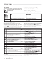
Betriebsanleitung • Operating Instructions
Pumping Operations With DCU
PM 0547 BE/S (0512)
- Turbomolecular Pumps -
Index
Page
Page
1. Introduction To These Instruction.......... 3
4. Error Codes ............................................. 14
2.1. General ................................................................................ 4
2.2. Parameter Overview, Numeric DCU ............................... 4
2.3 Parameter Overview, Operations Orientated................ 5
3. Pumping Operations ................................ 6
3.1. General ................................................................................ 6
3.2. Switching On The DCU...................................................... 6
Self-Testing......................................................................... 6
3.3. Short Overview, Operating ............................................... 6
3.4. Switching On The Pumping Station ................................ 7
Operations with mains voltages 90 - 132V ..................... 7
3.5. Switching Stand-By ON And OFF .................................... 7
3.6. Switching The Casing Heating ON And OFF.................. 7
3.7. Sealing Gas Valve Operations ......................................... 7
3.8. Operations With The Temperature Management
System (TMS) ..................................................................... 8
3.9. Gas Type Dependent Operations .................................... 8
3.10. Switching The Turbopump ON And OFF......................... 8
3.11. Setting Rotation Speed Switch Point.............................. 8
3.12. Rotation Speed Setting Mode.......................................... 9
3.13. Pressure Measurement .................................................... 9
3.14. Backing Pump Operations.............................................. 10
3.15. Switching Off The Pumping Station .............................. 11
3.16. Remote Control................................................................. 11
Operating Modes With The Remote Control .............. 11
Standard Remote Control ............................................... 11
Remote Control Priority................................................... 11
Remote Control “malfunction acknowledgement" ..... 12
3.17. Venting The Turbopump.................................................. 12
3.18. Operations Via Serial Interface RS 485 ........................ 13
3.19. Emergency Power Operations....................................... 13
3.20. Brake Mode (only with TC 600) ..................................... 13
3.21. Configuration Of The Accessories Input
And Output (only TC 100)................................................. 13
3.22. Configuration of The Analog Output (only TC 100)...... 13
Used Abbreviations
DCU
Operation and Display Unit
TC
Electronic Drive Unit
TCK
Electronic Drive Unit (Print Modul)
2
4.1.
4.2.
4.3.
4.4.
General .............................................................................. 14
Errors During Self-Testing.............................................. 14
Errors During Operations With The TC 600.................. 14
Warnings ........................................................................... 15
5. Supplementary Information .................. 15
Pictogram Definitions
WARNING
Warning!
Danger of an electric shock.
WARNING
Warning!
Danger of personal injury.
CAUTION
Caution!
Danger of damage to the unit or system.
PLEASE NOTE
☞
2. Parameters ............................................... 4
Please Note!
Attention to particularly important information
on the product, handling the product, or to a
particular part of the documentation.
Please note
Current operating instructions are also available via
www.pfeiffer-vacuum.net under “infoservice".
1. Introduction To These Instructions
The Display Control Unit DCU is a universal operating unit for
the control and monitoring of PFEIFFER vacuum pumps.
These operating instructions describe the operations in
respect of PFEIFFER VACUUM turbomolecular pumps. This
manual is a component of the complete operating manual for
your modular turbopump system. Depending on the configuration of your system, other operating instructions are included
in your delivery consignment (please see the table).
We make every effort to ensure that you are in possession of
all the necessary product information but should anything be
missing please get in touch with your local PFEIFFER
VACUUM representatives or telephone the hotline number
which you will find on the back cover of these operating
instructions.
The respective documents are also available in PDF file
format via the homepage www.pfeiffer-vacuum.de.
The following operating instructions are available for the TC
pump program:
Product
Definition
Turbomolecular Drag Pump
Pumping operations with the DCU, turbopumps
DCU 001, 100-600
TPS 100, 200, 300, 600
Casing heating, turbopump
Air cooling, turbopump
Water cooling, turbopump
Backing Pump relay box
Temperature Management System TMS
Pfeiffer protocol RS 232/RS 485
Level Converter RS 232/RS 485
TVF 005
TIC 250
PWM-Box
TCS 010
Cover IP 54 for TC 600
TBU 600
Definition of the turbopump
Operating definitions /parameters
Description of the control unit/installation
Description of the power pack
Description of the casing heating
Description of the air cooling system
Description of the water cooling system
Description of the backing pump control
Description of the TMS installation
Description of the serial interface protocol
Description of the pumping control via the RS 232
Description of the venting valve
Description of the Profibus
Description of the pulse width modulation
Description of the Pumping Station Control Unit
Description of the water protection cover
Description of the brake unit
Operating Manual Number
dependent on the type of pump*
PM 800 547 BE
PM 800 477 BE
PM 800 521 BE
PM 800 542 BE
PM 800 543 BE
PM 800 546 BE
PT 0030 BE
PT 0099 BE
PM 800 488 BE
PM 800 549 BE
PM 800 507 BE
PM 800 599 BE
PM 800 563 BE
PT 0045 BE
PT 0024 BE
PT 0018 BE
* The number is available from PFEIFFER VACUUM Service or from the internet address shown in this manual.
2. Parameter
2.1. General
All function relevant elements of the display control unit or
pump are available in the DCU in the form of parameters.
Each parameter has a parameter number and a clear text
designation, for example [P:026] «OpMode TMP».
Parameter Typ
Setting command
Status request
Set value standard
The value of the parameter is always readable and in some
instances can be altered. In principle there are three different
types of parameter:
Function
Activating/deactivating a parameter
Parameter status reques (readable only)
Altering a parameter
To adapt these parameters to the individual requirements of
the user, the DCU provides two different parameter sets
which are distinguished by the number of parameters
involved. The respective parameter set is selected via [P:794]
«Param. set». The parametering is always active.
Parameter Set
Basic parameter set
Extended parameter set
Comment
Only parameters sorted according
to number and parameter type
Complete parameter set, sorted
according to number and parameter type
Setting [P:794] «Param. set»
0
1
Parameters which do not appear in the display can nevertheless be operated via the serial interface.
3
#
300
301
302
303
304
305
306
307
308
309
310
311
312
313
314
315
316
319
331
333
334
335
340
349
350
351
360
361
362
363
364
365
366
367
368
369
Display
Oil defic
Error code
Set rotspd
Act rotspd
TMP I-Mot
TMP Op hrs
Drv Softw
TMP DClink
Drv Op hrs
TMP finspd
TMP power
Cycl count
TMS ActTmp
TMS steady
TMS maxTmp
Heat type
Pressure
Drv Name
Ctr Name
Ctr Softw
Past Err1
Past Err2
Past Err3
Past Err4
Past Err5
Past Err6
Past Err7
Past Err8
Past Err9
Past Err10
Name, Description
Unit remote controlled, not choosable by
Oil deficiency turbopump
Rotation switch point attained
Actual error code „no Err“, „Errxxx“ or „Wrnxxx“
Over temperature Electronic drive unit
Over temperature turbopump
Set rotation speed attained
Turbopump accelerates
Set rotation speed TMP in Hz
Actual rotation speed TMP in Hz
Motor current TMP in A
Operating hours TMP in h
Software version electronic drive unit
Motor voltage TMP in V
Operating hours electronic drive unit
Final rotation speed TMP in Hz
Motor power TMP in W
Cycle counter
Heating TMS, actual value in ºC
TMS regulator engaged ON/OFF
Maximum TMS temperature occured in ºC
Heating type 0=conventional heating, 1=TMS
Actual pressure value in mbar 3)
Unit type electronic drive unit
Unit type operating and display unit 3)
Software version Display and Control Unit DCU 3)
Error storage, Position 1 (last error occuring)
Error storage, Position 2
Error storage, Position 3
Error storage, Position 4
Error storage, Position 5
Error storage, Position 6
Error storage, Position 7
Error storage, Position 8
Error storage, Position 9
Error storage, Position 10
–
–
0
0
0
0
2000
2000
15.0
99999
0
0
0
0
0
5
OFF
5
0
1E-10
200.0
99999
2000
1000
99999
200
ON
200
1
1E3
fact. setting
–
–
–
–
–
–
–
–
–
–
–
–
–
–
–
–
–
–
–
–
–
–
–
–
–
–
–
–
–
–
–
–
–
–
–
RS 485
R
R
R
R
R
R
R
R
R
R
R
R
R
R
R
R
R
R
R
R
R
R
R
R
R
R
R
R
R
R
R
R
R
R
R
R
fact. setting
154) / 85)
80
40
50.0(*)
80
0
0
66
20
50
3600
–
0
0
795
1
RS 485
R/W
R/W
R/W
R/W
R/W
R/W
R/W
R/W
R/W
R/W
R/W
R/W
R/W
R/W
R/W
R/W
Set values (readable and writable)
#
700
701
704
707
708
710
711
717
719
720
721
738
777
794
795
797
Display
TMP RUTime
Switch pnt
TMSheatset
TMProt set
DrvPwr set
BKP Poff
BKP Pon
Stbyrotset
Switch pnt2
Vent frequ
Vent time
Gaugetype
PumpRotMax
Param. set
Servicelin
Address
Name, Description
maximum run-up time in mins
Rotation speed switchpoint in %
TMS heating temperature set value in ºC
Rotation speed set value in rotation speed setting operations in %
Drive power set in %
Pmin for backing-pump interval operations [W]
Pmax for backing-pump interval operations [W]
Rotation speed set value at standby operations (%)
Rotation speed switchpoint2 in %
Venting frequency as a % of the final rotation speed of the TMP
Venting time in s
Vacuum pressure gauge type 3)
min
1
50
30
20.0
10
0
0
20
5
40
6
max
120
97
90
100.0
100
1000
1000
100
97
98
3600
Specific nominal rotation speed [Hz]
Parameter set 0 = basic parameter set; 1 = extended parameter set 3)
insert service line
Unit address
0
0
2000
1
1
255
(*) Function can only be affected via remote plug (X16)
A number/parameter in bold type is a basic parameter set.
= Parameter setting is saved internal and activated after re-switching on.
4
1) R = Parameter readable via interface /W = parameter writeable via interface.
2) See Interface instruction ”Pfeiffer Protocol RS 232/485” / PM 800 488 BN
3) Parameter only for DCU
4) TC 600/750
5) TC 100/TCK 100
TC 750-E074
max
TC 100/TCK 100
min
Status request (only readable)
0
0
0
0
0
0
0
0
7
7
7
7
7
0
7
7
7
7
7
•
•
•
•
•
•
•
•
•
•
•
•
•
•
•
•
•
•
•
•
•
•
•
•
•
•
•
•
•
•
•
•
•
•
•
•
•
•
•
•
•
•
•
•
•
•
TC 750-E074
ON
ON
ON
ON
2
2
1
1
2
ON
2
1
3
3
2
RS 4851)
R/W
R/W
R/W
W
R/W
R/W
R/W
R/W
R/W
R/W
R/W
R/W
R/W
R/W
R/W
R/W
R/W
R/W
R/W
0
0
0
4
0
0
0
0
1
1
2
1
4
2
1
1
1
1
1
0
1
7
3
4
4
4
4
4
4
4
4
4
4
4
4
4
•
•
•
•
•
•
•
•
•
•
•
•
•
•
•
•
•
•
•
•
•
•
•
•
•
•
•
•
•
•
•
•
•
•
•
•
•
•
•
•
•
•
•
•
•
•
•
•
•
•
•
•
•
•
•
•
•
•
•
•
•
•
•
•
•
•
•
•
•
•
•
•
•
•
•
•
•
•
•
•
•
•
•
•
•
•
•
•
•
•
•
•
•
•
TC 750-E074
OFF
OFF
OFF
OFF
0
0
0
0
0
OFF
0
0
0
0
0
fact. setting
OFF
OFF
ON
–
ON(*)
ON(*)
OFF
ON(*)
0
0
0 (*)
0
0
OFF
0
0
0
1
0
TC 600/750
max
ON
ON
ON
TC 100
min
OFF
OFF
OFF
TC 600/750
Name, Description
Pre-selection, heating.ON/OFF
Standby ON/OFF
Run-up time monitoring, ON/OFF
Error acknowledgement
Pumping station ON/OFF
Venting enable ON/OFF
Pre selection brake ON/OFF
Motor Turbopump ON/OFF
Configuration output K1; 0=switchpoint attained; 1= TMS regulator; 2=var. switchp.
Operations mode backing pump, 0=non-stop; 1=intermittent; 2=switch on delayed
Operations mode TMP 0=final rot. speed op.; 1=rot. speed setting m.
Gas mode 0=heavy inert gases; 1=other gases
Remote operations mode 0=standard, 1=Remote priority, 2 Remote error acknowl.
Drive unit operations mode OFF=max., ON=reduced power intake
Venting mode 0=controlled venting ; 1=no venting; 2=venting ”On”
Configuration heating output; 0=Heat/TMS operations; 1=sealing gas valve control
Configuration accessories ON/Output 1 (see chapter 3.21.)
Configuration accessories ON/Output 2 (see chapter 3.21.)
Configuration Analog Output 1 0=Rot Speed; 1=Power; 2=Current
TC 100
TC 600/750
Display
Heating
Standby
RUTime ctr
Error ackn
Pump stat
Vent enab
Brake enab
Motor TMP
Conf. Out1
OpMode BkP
OpMode TMP
Gas mode
Opmode rem
OpMode Drv
Vent mode
Conf Out4
Conf I/O1
Conf I/O2
Conf AO1
Data type2)
#
001
002
004
009
010
012
013
023
024
025
026
027
028
029
030
032
035
036
055
Type2)
Setting Commands (readable and writable)
Type2)
2.2. Parameter Overview, numerical, DCU
1
1
1
2
7
1
1
2
1
7
1
4
1
7
7
1
•
•
•
•
•
•
•
•
•
•
•
•
•
•
•
•
•
•
•
•
•
•
•
•
•
•
•
•
•
•
•
•
•
•
•
•
•
2.3. Parameter Overview, Operations Oriented, DCU
#
Display
Name, Description
min
max
fact. set
RS 485
Sect.
OFF
1
50
5
ON
120
97
97
ON
15 / 8
80
20
•
•
•
3.4.
3.4.
3.4.
3.11.
0
0
0
0
0
2000
15.0
200.0
1000
99999
–
–
–
–
–
•
•
•
•
•
3.4.
3.4.
3.1.
OFF
OFF
OFF
0
0
OFF
0
0
20
20.0
ON
ON
ON
1
1
ON
2000
2000
100
100.0
OFF(*)
–
–
0
0
OFF
–
–
66
50.0(*)
•
•
•
•
•
•
•
•
•
•
3.5.
3.4.
3.10.
3.11.
3.8.
3.4.
3.4.
3.1.
0
0
5
OFF
5
0
30
1
1
200
ON
200
2
90
0(*)
0
–
–
–
–
40
•
•
•
•
•
•
•
3.6.
3.7.
3.8.
3.8.
3.6., 3.8.
3.8.
OFF
0
40
6
ON
2
98
3600
ON
0(*)
50
3600
•
•
•
•
3.15.
3.15.
3.15.
Operations mode backing pump, 0=non-stop; 1=intermittent; 2=switch on delayed
Configuration Accessories ON/Output 1
Configuration Accessories ON/Output 2
Actual pressure value in mbar
Vacuum pressure gauge type
Pmin for backing-pump interval operations [W]
Pmax for backing-pump interval operations [W]
0
0
0
1E-10
2
3
3
1E3
1000
1000
•
•
•
•
•
•
•
3.12.
3.21.
3.21.
3.11.
3.11.
0
0
0
0
1
–
–
0
0
Preselection Brake ON/OFF
Configuration output K1 0=switchpoint attained; 1= TMS regulator
Remote operations mode 0=standard, 1=Remote priority, 2 Remote error acknowl.
Configuration Analogue Output 1
Actual error code „no Err“, „Errxxx“ oder „Wrnxxx“
Software version electronic drive unit
Software version Display and Control Unit
Parameter set 0=basic parameter set; 1=extended parameter set
insert serviceline
Unit address
OFF
0
0
0
ON
1
2
2
0
1
1
255
OFF
0
0
0
–
–
–
0
795
1
•
•
•
•
•
•
•
•
•
•
3.8.
3.14.
3.19.
–
–
–
3.4.-3.15.
PM477BD
–
–
–
–
–
–
–
–
–
–
–
•
•
•
•
•
•
•
•
•
•
4.3.
4.3.
4.3.
4.3.
4.3.
4.3.
4.3.
4.3.
4.3.
4.3.
Run-up time and rotation speed switchpoint
004
700
701
719
RUTime ctr
TMP RUTime
Switch pnt
Switch pnt2
Run-up time monitoring, 0=OFF; 1=ON
maximum run-up time in mins
Rotation speed switchpoint in %
Rotation speed switchpoint 2 in %
General operating information
315
310
313
316
311
TMP finspd
TMP I-Mot
TMP DClink
TMP power
TMP Op hrs
Final rotation speed TMP in Hz
Motor current TMP in A
Motor voltage TMP in V
Motor power TMP in W
Operating hours TMP in h
Operating adjustment turbopump
002
010
023*
026
027
029
308
309
717
707
Standby
Pump stat
Motor TMP
OpMode TMP
gas mode
OpMode Drv
Set rotspd
Act rotspd
Stbyrotset
TMProt set
Standby ON/OFF
Pumping station ON/OFF
Motor Turbopump ON/OFF
Operations mode TMP 0=final rot. speed oper., 1=rot. speed setting
Gas mode 0=heavy inert gases; 1=other gases
Operating mode drive unit OFF=max., ON=reduced power consumption
Set rotation speed TMP in Hz
Actual rotation speed TMP in Hz
Rotation speed set value at standby operations (%)
Rotation speed set value in rotation speed setting operations in (%)
3.11.
Heating/cooling turbopump
001
032
331*
333*
334*
335*
704*
Heating
Conf Out4
TMS ActTmp
TMS steady
TMS maxTmp
Heat type
TMSheatset
Pre-selection, heating. 0=OFF; 1=ON
Configuration heating output; 0=Heat/TMS operations; 1=sealing gas valve control
Heating TMS, actual value in ºC
TMS regulator engaged ON/OFF
Maximum TMS temperature occured in ºC
Heating typ 0=conventional heating, 1=TMS, 2=cooling
TMS heating temperature set value in ºC
Vent valve controlling turbopump
012
030
720
721
Vent enab
Vent mode
Vent frequ
Vent time
Venting enable ON/OFF
Venting mode 0=automatic venting ; 1=do not vent; 2=venting ”On”
Venting frequency as a % of the final rotation speed of the TMP
Venting time in s
Pumping station controlling
025
035**
036**
340
738
710
711
OpMode BkP
Conf I/O1
Conf I/O2
Pressure
Gaugetype
BKP Poff
BKP Pon
Others
013*
024*
028
055
303
312
351
794
795
797
Brake enab
Conf. Out1
OpMode rem
Conf AO1
Error code
Drv Softw
Ctr Softw
Param. set
Servicelin
Address
Table of failures
360
361
362
363
364
365
366
367
368
369
Past Err1
Past Err2
Past Err3
Past Err4
Past Err5
Past Err6
Past Err7
Past Err8
Past Err9
Past Err10
Error storage, Position 1 (last error occuring)
Error storage, Position 2
Error storage, Position 3
Error storage, Position 4
Error storage, Position 5
Error storage, Position 6
Error storage, Position 7
Error storage, Position 8
Error storage, Position 9
Error storage, Position 10
* only for TC 600/750
** only for TC 100 / TCK 100
(*) Function can only be affected via remote plug (X16)
• Function can be called by RS 485
5
3. Pumping Operations
3.1. General
On delivery the pre-set basic parameter sets contain the
following parameters:
Setting Command [P:0xx]
001: Heating (ON/OFF)
002: Stand-by (ON/OFF)
Status Request [P:3xx] (readable only)
308: Set rotation speed, TMP (in Hz)
309: Actual rotation speed TMP (in Hz)
310: TMP Motor current (in A)
311: operating hours, TMP (in h)
Set Value Standard [P:7xx]
700: maximale Anlaufzeit (in min)
701: Schaltpunkt (in %)
794: Parametersatz
On delivery, parameter [P:794] «Param. Set» has been preset
to the value ”0” (basic parameter set). By setting the value to
”1” you access the extended parameter set.
3.2. Switching On The DCU
3.3. Short Overview Operation
➡ Make the connection to the Serial Interface RS 485.
DCU 001:
➡ Switch on the external voltage supply to the TOC.
DCU 100/150/200/300/600:
➡ Switch on the DCU with switch S1 on the rear panel.
Self Testing
After switching on, the DCU performs a self-test and also a
test on the connected turbo electronics. During the test a bar
appears in the display in line 4 and this shows the progress of
this procedure.
Display test: All signs in the LC display are shown for a
short time in black.
LEDs test: During the whole testing procedure the red and
the green LEDs illuminate.
DCU self-test: The DCU hardware tests itself.
Testing the connection to the turbo electronics: The
correct connection to the turbo electronics and their identity are checked.
Parameter test: Information regarding the parameters is
loaded.
Identification of the connected components: The designation of the drive unit is displayed.
Providing there are no errors the DCU is now ready to
operate.
Selecting Parameters
➡ Selecting parameters with push-button
or
(backwards)
(forwards). keeping the key depressed enables
rapid scrolling.
Setting Parameters
➡ Select Parameter.
➡ Depress key-button
and
simultaneously till an
arrow (--->) will appear in the second line from the top.
–> Arrow disappears, if there is no setting after 8 sec..
➡ With key-button
button
reduce the value and with key-
increase the value.
➡ Depress key-button
and
arrow (--->) disappears.
–> The Parameter is set.
simultaneously till the
Error acknowledgement
➡ Depress key-button
for a duration of min. 2 seconds.
For a more comprehensive description please refer to the
operating instructions for the DCU / PM 800 477 BN.
6
3.4. Switching The Pumping Station ON/OFF
Please Note:
Before switching on the pumping station the set value [P:7xx]
and setting commands [P:0xx] should be checked for their
suitability with regard to the selected pump and pumping
process.
➡ Remove the remote plug on the TC (only TC 600).
➡ Switch on switch S1 on the mains power unit.
➡ Select «7794 : Param. Set» and set to «1».
➡ Check the relevant set value standards and setting
commands (Section 2.2.).
➡ Select «0023 : motor TMP» and set to «ON» (only TC 600).
➡ Switch on the pumping station with key
on the DCU
or via the serial interface remote control or Parameter
[P:010] «Pump stat» on the DCU.
Start-up of the turbopump
After successful completion of the self test, the turbopump
starts up and the backing pump is driven. The rotation speed
switchpoint [P:701] must be attained within the pre-set startup time [P:700]. Both parameters can be matched to the
process. If an error code is displayed please refer to the error
code table in section 4.
When the error is acknowledged the start-up time is reset.
Stand-by is recommended during operating breaks. The function can also be selected via the remote control or the serial
interface.
During activ stand-by the rotation speed set point [P:707]
refers always to the adjusted stand-by rotation speed [P:717].
Stand-by mode is not possible in rotation speed setting mode
(please see section 3.12).
At stand-by mode, pumps with integrated oil pump are first
accelerated to 60% of their nominal rotation speed even if the
set stand-by rotation speed is <60% x fnom.
During this time the final rotation speed ist shown via [P:308]
«set rotation speed». After reaching 60% of speed the
adjusted stand-by rotation speed is displayed [P:717].
3.6. Switching The Casing Heating ON/OFF
The TC 600 automatically recognizes a connected casing
heating and sets according to the parameters [P:355] «Heat
type» to «0». If no heating is connected «1» is displayed.
To control the casing heating on the TC 100/TCK 100 it is
necessary to select the respective accessory input and
output (see section 3.21.)
Operations with mains voltages 90 - 132V
CAUTION
In case of this rated voltage the output power of
the TPS (power supply) or DCU 600 (Control unit
with power supply) is reduced.
Therefore the power input of the pump must be
adapted with the DCU and via the parameters
[P:029] and [P:708].
➡
➡
➡
➡
Select «794 : Param. Set» and set to «11».
Select «029 : OpMode drv»..
Set to «11» = reduced power take-up TC600.
Select «7708 : DrvPwr Set» and adjust to the relating pump
type (see table below).
Pump type
➡
➡
➡
➡
Select «794 : Param. Set» and set to «11».
Select «335 : Heat type» and check setting to «00».
Select «001 : Heating».
OFF» or «O
ON».
Select «O
The casing heating is switched on and off dependent on the
rotation speed switchpoint. Undershooting the rotation speed
switchpoint causes the heating to be switched off. The status
of the casing heating can be seen on the LC display on the
DCU.
The function ”casing heating” can be called up either via the
serial interface or the remote control.
Adjustment [P:708]
1001/1601/2201
80%
1201/1501/1801/2101/2301
60%
If the TC is not set the error code «EE001» or «FF007» is displayed.
3.5. Switching Stand-By ON/OFF
➡ Select «002 : Standby».
OFF» oder «O
ON».
➡ Select «O
”Stand-by mode” is the operation of the pump at 66% of its
final rotation speed (factory setting).This value is changeable.
➡ Select «717 : Stbyrotset».
➡ Adjust Standby rotation speed in the range of 20-100%.
3.7. Sealing Gas Valve Control
Operation of the heating output "Heat/TMS" may be
configured through [P:032]. At this output also a sealing gas
valve may be driven by a venting valve.
➡ Select «7794 : Param. Set» and set to «11».
➡ Select «0032 : Conf Out4» and set to «11».
A valve connected to the connection "Heat/TMS" can be switched on at any time independently only through [P:001] or the
corresponding control input "Heating ON" at the remote
connector.
➡ Select «0001 : Heating».
OFF» or «O
ON».
➡ Choose «O
7
3.8. Operations With Temperature Management System (TMS) (only TC 600/750)
3.9. Gas Type Dependent Operations
To protect the rotors against overheating, the maximum
power on some turbopumps is limited to the nominal rotation
speed. Normally, with a lower, pre-set rotation speed, more
power can be provided. This frequency/power curve is
dependent on the type of gas.
Turbopump with TMS
95 Connection box
96 Connecting cable
for heating elements
97 Sensor connection
Selecting the gas type
➡ Select «7794 : Param. Set» and set tof «11».
➡ Select «0027 : gas mode».
➡ Select «00» for heavy, noble gases and «11» for other gases.
97
96
95
Power
Gas type curve
The Temperature Management System (TMS) comprises a
regulatable heating system which is installed in the forevacuum part of the turbomolecular pump. Heating up to a
maximum of 90°C prevents the condensation of process
gases or by-products in this part of the pump.
As a matter of principle, the TMS heating is only activated on
attainment of the rotation speed switchpoint [P:701] The TC
600 automatically recognizes a connected TMS heating unit
and sets the parameter [P:335] «Heat type» to «1».
Activating TMS mode
➡ Select «7794 : Param. Set» and set to «11».
➡ Select «3335 : Heat type» and check setting.
➡ Select «7704 : TMSheatset».
➡ Enter set temperature value «30°C...90°C».
➡ Acknowledge the value.
➡ Select «0001 : Heating» and set to «11».
With [P:001] «Heating» The TMS heating can be activated
and deactivated at any time with «1» or «0» respectively.
In addition to the above parameters (which are used to start
the TMS) other parameters are also available to support
working with the TMS:
Calling up the TMS temperature
➡ Select «3331 : TMS ActTmp» and read off the temperature.
TMS set temperature attained?
➡ Select «3333 : TMS steady» and read off the information.
Function of switch “output 1” (only TC 600)
The switch output 1 is normally set to "high" on the rotation
speed switchpoint being exceeded. The function of switch
output 1 can be re-programmed so that switch output 1 is
"high" only when the TMS set temperature is attained.
➡ Select «0024 : Conf. Out1» and set to «11».
This information can be used, for example, as an input signal
for a higher ordered process control.
D
B
D-C = Gas mode «0»
B-A = Gas mode «1»
Frequency
Run up
A
C
fnom
The rotation speed is reduced when the gas dependent maximum power is exceeded until there is equilibrium between
the permissible power and the gas friction. To avoid rotation
speed fluctuations it is recommended to set (in rotation speed
setting mode) the equilibrium frequency or a somewhat lower
frequency.
3.10. Switching The Turbopump ON/OFF
(only TC 600/750)
During pumping station operations (pumping station "ON") the
turbopump can be switched on and off separately:
➡ Select «0023 : Motor TMP».
OFF», or «O
ON» as required.
➡ Select «O
3.11. Adjusting Rotation Speed Switchpoint
The speed switch point may be used to generate the message
"Pump ready". As soon as the speed exceeds, respectively
drops below the speed switch point 1 [P:701] «Switch pnt» the
switched output is energized or de-energized. The factory
default setting is 80%.
Simple Switch Point Adjustment (upper value only)
➡ Select «7701 : Switch pnt» .
➡ Adjust the switch point in the range between 50-97%.
➡ Confirm the adjustment.
Double switch point adjustment (lower and upper value)
Depending on the setting of the parameter [P:024] «Conf
Out1» the lower and the upper speed switch point may be
influenced simultaneously.
The factory default setting is 20, respectively 80% of the final
rotation speed.
8
The speed switch point can now be varied through two
further parameters:
Activated drive
ON") the
In the case of an activated drive ([[P:023] set to "O
switch point output is driven independently of the setting for
the switch point 1 [P:701]. As soon as the speed exceeds the
adjusted switch point, the switch point output is energized.
The setting may be selected between 50 and 97% of the final
rotation speed.
➡ Select «7701 : Switch pnt».
➡ Adjust the switch point in the range between 50-97%.
➡ Confirm the adjustment.
Deactivated drive
OFF") the
In the case of a deactivated drive ([[P: 023] set to "O
switch point output is driven independently of the setting for
the switch point 2 [P:719]. As soon as the speed drops below
the adjusted switch point, the switch output is de-energized.
The setting may be selected between 5 and 97% of full speed.
➡ Select «7719 : Switch pnt2».
➡ Adjust the switch point in the range between 5-97%.
➡ Confirm the adjustment.
3.12. Rotation Speed Setting Mode
The rotation speed setting mode is selected if the turbopump
volume flow rate should be reduced. The pressure ratio of the
pump reduces exponentially with the rotation speed.
Rotation speed standard in rotation speed setting mode
➡ Select «7794 : Param set» and set to «11».
➡ Select «7707 : TMProt set».
➡ Select the rotation speed in the range from 20%.....100%.
Operating mode, turbopump
➡ Call up «0026 : OpMode TMP».
➡ Select "11" for rotation speed setting mode.
☞
PLEASE NOTE
The stand-by mode is ineffective in rotation
speed setting mode. The rotation speed switchpoint has been fixed at 20%. The rotation speed
setting mode can be set via the remote control
or the serial interface.
3.13. Pressure Measurement
With the use of a high vacuum pressure gauge the pressure
in the vacuum chamber is shown in the DCU display.
PLEASE NOTE
☞
➡ Select «0024 : Conf Out1».
➡ Set the parameter to «22».
➡ Confirm the adjustment.
Basically an exactly pressure measurement is
not possible by the DCU. This is especially indicated at linear working gauges in the lower
pressure range. In case of doubt an intended
measuring unit should be used.
The following pressure gauges are automatically recognized
by the DCU:
Pressure Gauge
pmin [mbar] pmax [mbar]
TPR 2xx
5E-4
1E+3
PKR 2xx
5E-9
1E+3
ACR 261/CMR 261/APR 250/260
1E-1
1E+3
ACR 262/CMR 262
1E-2
1E+2
ACR 263/CMR 263
1E-3
1E+1
CMR 264
1E-4
1E0
Requesting the type of pressure gauge
➡ Select «7794 : Param set» and set to «11».
➡ Select «7738 : gauge type».
➡ Read off the pressure gauge type.
Some pressure gauges can only be recognized as a group
(e.g. ACR 261-ACR 263) and have to be set manually.
Requesting the actual pressure value
➡ Select «7794 : Param set» and set to «11».
➡ Select «3340 : Pressure».
➡ Read off the pressure value in mbar.
The following can be displayed, depending on the pressure
gauge type:
Display (Example)
Appears when
«---- mbar»
«<5E-4mbar»
no pressure gauge is connected
measuring range is non-attained (depending
on the pressure gauge in use)
measuring range is exceeded (depending
on the pressure gauge in use)
valid pressure measurement range
pressure gauge type not yet identified
pressure gauge TPR 250 connected
pressure gauge ACR 261, ACR 262 oder ACR
263 connected but not yet selected (in this
case the display «id fam» [P:340] is shown)
error in the pressure gauge
«>1E3mbar»
«6.3E-9mbar»
«idfam mbar»
«TPR250»
«ACR..?»
«Error!»
Pumps with integrated oil pumps are first accelerated, in
rotation speed setting mode, to 60% of their rated rotation
speed, also where the set rotation speed is <60% xfnom.
During this time the final rotation speed ist shown via [P:308]
«set rotation speed». After reaching 60% of speed the
adjusted stand-by rotation speed is displayed [P:717].
9
3.14. Backing Pump Operations
The operating modes "non-stop operations", "interval operations" or "Switch ON delayed" can be selected depending on
the selected backing pump and the vacuum application.
Interval operations can be selected, for example, to prolong
the working life of the diaphragms in diaphragm vacuum
pumps. The backing pump is switched on and off depending
on the power take-up of the turbopump.
CAUTION
Rotary vane pumps must not be used for
internal operations.
Non-stop operations backing pump
➡ Select «7794 : Param set» and set to «11».
➡ Select «0025 : OpMode BkP» and set to «00» for non-stop
operations.
Interval operations backing pump
➡ Select «7794 : Param set» and set to «11».
➡ Select «0025 : OpMode BkP» and set to «11» for interval
operations.
For intermittent operations involving the backing pump, either
a diaphragm pump with integrated semiconductor relay or a
relay box with semiconductor relay should be used. The
backing pump is switched on and off in accordance with the
power take-up levels of the turbopump.
Differing power take-up levels on an idling turbopump lead to
differing pressure switchpoints on various pumps. In addition,
on diaphragm pumps there are differing final pressures resulting from the gas ballast equipment. This means that ideal
pressure switchpoint setting via the power take-up level is
not possible. Nevertheless, the advantage of intermittent
operations can still be exploited by setting the pressure
switch threshholds individually. In this respect operations
between 5 and 10 mbar are recommended.
A vacuum meter, a DCU and a dosing valve are required in
order to set the switching threshhold. Instead of the vacuum
meter a vacuum gauge can be connected directly to the DCU.
10
Setting the switching threshholds
➡ Select «3340 : Pressure».
➡ Admit air into the fore-vacuum line with the dosing valve
while the pumping station is running until the fore-vacuum
pressure increases to 10 mbar.
➡ Select «3316 : TMP power».
➡ Read off the take-up power at 10 mbar.
➡ Select «7711 : BKP Pon».
➡ Save the read-off take-up power as the upper switching
threshhold.
➡ Proceed analogically with the lower switching threshhold.
Take 5 mbar as the pressure value.
➡ Select «7710 : BKP Poff».
➡ Save the read-off take-up power as the lower switching
threshhold.
Switch On Delayed
➡ select «7794 : Param set» and set to «11».
➡ select «0025 : OpMode BkP»; choose «22» for delayed switch
on.
When simultaneously switching on the turbopump and the
backing pump, the gas flow could cause a failure with the
error message E913 during the starting phase. In order to
prevent this, it is recommended to first start the turbopump
and then the backing pump or open a driven fore-vacuum
valve.
In the operating mode “delayed switch on” after activation of
the parameter «Pump start» [P:010] and «Motor TMP» [P:023]
the turbopump is started first and as soon as a speed of 6 Hz
has been exceeded the backing pump controlled via the TC is
then switched on.
Should the backing pump or a fore-vacuum valve be driven by
a higher level system controller, it is recommended to proceed in the same way.
3.15. Switching Off The Pumping Station
➡ Depress
on the front panel. As an alternative, the
pumping station can be switched off via the remote
control, the serial interface or [P:010].
3.16. Remote Control
The following functions can be activated via the remote
control (please also refer to the operating instructions for the
respective turbopump):
TC 600:
PIN
2
3
4
5
6
7
Function
Venting enable ”ON/OFF”
Turbopump ”ON/OFF” /remote priority ”ON/OFF”
Pumping Station ”ON/OFF”
Heating ”ON/OFF”/Error acknowledgement
Stand-by ”ON/OFF”
Rotation speed setting mode via pulse width
modulation (PWM).
TC 100/TCK 100:
PIN
Function
2/d4
3/b4
4/z4
5/d6
6/b6
- Remote Priority ”ON/OFF”
- Accessory 1 ”ON/OFF”
- Accessory 2 ”ON/OFF”
- Pumping Station ”ON/OFF”
- Standby ”ON/OFF” / Reset
Operating modes with the remote control
Basically there are three different possibilities with regard to
the remote control with differing priorities with respect to the
remote control functions:
Standard Remote Control
➡ Select «0028 : OpMode rem» and set to «0».
Priority ON
In certain application cases as, for example, SPS control, the
remote control functions can be assigned prioritized
switching.
➡ Select «0028 : OpMode rem» and set to «11». Bridge pin 1/pin
3 on the connecting plug ”remote”.
–> All set functions will be switched off excepting ”motor,
turbopump ON” which remains on ”ON”.
–> The remote control functions can only be set via the
connecting plug ”remote”. The DCU keyboard/serial interface is inactive.
The functions:
- Heating ON/error acknowledgment
- Stand-by ON
- Pumping station ON
- Enable venting
are activated and deactivated with the signals «1» and «0»
respectively. In the rotation speed setting mode the set value
standard is processed exclusively via pin 7 on the connecting
plug ”remote”.
If pin 3 on the connection ”remote” should be set to ”0”:
-> Values set via the remote control will be taken over except
in rotation speed setting mode. Here, the set value standard is processed via the serial interface or the keyboard.
Priority OFF
➡ Select «0028 : OpMode rem» with f=0 Hz and set to «11».
–> All set functions will be switched off excepting ”motor,
turbopump ON” which remains on ”ON”.
➡ Set Pin3/”Remote” to «0».
–> Operating is only possible via the DCU keyboard/serial
interface (remote control not active).
–> -Set values are not saved.
–> In rotation speed setting mode the rotation speed set via
the keyboard or serial interface will be taken over.
If «0028 : OpMode rem» should be re-set to «00»:
–> Values set via the keyboard or serial interface will be
taken over. Values set with «1» via the remote control will
also be taken over.
The individual functions which can be operated with the remote control are activated via ”SPS High Level”. Activated
individual functions cannot be operated via the serial interface nor the keyboard. Individual functions deactivated with the
remote control can be operated via the serial interface or the
keyboard.
Remote Control Priority
Only TC 600:
CAUTION
«0028 : OpMode rem» may only be altered to
«OFF» when the pump is switched off («0023 :
Motor TMP»).
11
Only TC 100/TCK 100:
Priority ON
➡ Select «0028 : OpMode rem» and set to «11».
TC 100
➡ Bridge pin 2/pin 7 on the connecting plug X3.
TCK 100
➡ Bridge pin d4/pin z28 on the connecting plug X4.
–> All set functions will be switched off.
–> The remote control functions can only be set via the
connecting plug X3. The DCU keyboard/serial interface is
inactive.
The functions:
- Accessory 1 ON
- Accessory 2 ON
- Pumping station ON
- Standby/Reset ON
are activated and deactivated with the signals «1» and «0»
respectively.
Priority OFF
➡ Select «0028 : OpMode rem» and set to «11».
➡ Remove bridge pin 2/pin 7 on the connecting plug X3.
–> Values set via the remote control will be taken over.
–> Operating is only possible via the DCU keyboard/serial
interface (remote control not active).
–> -Set values are not saved.
If «0028 : OpMode rem» should be re-set to «00»:
–> Values set via the keyboard or serial interface will be
taken over. Values set with «11» via the remote control will
also be taken over.
Remote Control “Malfunction Acknowledgement"
If the reset input on the remote control is not used, it can be
utilized as an external malfunction acknowledgement via the
remote control; this means that after a switch off and
subsequent switch on via the ""Motor TMP" or "Pumping Station" inputs, a malfunction acknowledgement will first be
executed.
➡ Set «0028 : OpMode rem» to «22».
12
3.17. Venting The Turbopump
Venting is possible after the pump has been switched off.
Basically, a delay time of 6 seconds is observed before each
venting procedure to ensure that any possible high vacuum
valve is closed. In a currentless state the venting valve is
closed. Where a malfunction (error) is involved venting will
proceed in accordance with the selected venting mode.
Three types of venting modes can be selected in the extended
parameter set:
➡ Select «7794 : Param set» and set to «11».
➡ TC 600: Allocate venting release via bridge PIN 1 and PIN 2
on the “remote” plug.
➡ TC 100: Allocate venting release via bridge PIN 1 and PIN 3
respectively PIN 4 (according to the output configuration).
➡ TCK 100: Allocate venting release via bridge z28 and b4
respectively z4 (according to the output configuration).
or
ON».
➡ Call up «0012 : Vent enab». Select «O
➡ Call up «0030 : Vent mode». Select «00», «11» oder «22».
Venting mode «00»: automatic venting
Automatic venting means that venting begins at a specific frequency [P:720] after the pumping station has been switched
off or a mains power failure and continues for a specific duration [P:721].
In the event of a mains power failure, the set duration value
cannot be guaranteed.
➡ Select «7720 : Vent frequ».
➡ Set the venting frequency between «40-98%».
➡ Select «7721 : Vent time».
➡ Set the venting duration in sec. between «00» and «33600».
–> The venting valve is closed after mains power has been
restored.
Venting mode «1»: venting OFF
–> The pump will not be vented.
Venting mode «2»: venting ON
–> When the pumping station is switched off, in cases of
malfunction and in the event of a power failure, after a
time lag of 6 seconds, venting takes place. If a high
vacuum valve is installed, it can be closed in the
meantime. Where a mains power failure is involved,
venting will only take place as long as the pump is able to
supply power to the venting valve. After power has been
restored the venting valve stays open. It closes when the
pumping station is switched on.
3.18. Operations Via Serial Interface RS 485
The group address of the TC 600 is 960 of the TC 100/TCK 100
is 950. All units connected to the bus must have differing serial interface addresses [P:797]. The connection of an RS 232
(for example, a PC) is possible via Level Converter
PM 051 054-X. The description of the data communication
(PFEIFFER VACUUM protocol) can be found in Operating
Instructions PM 800 488 BN.
3.19. Emergency Power Operations
If during turbopump operations the power fails (warning
«FF007»), the pump rotor acts as a generator and takes over
the supply of power for the electronics. In addition, a power
failure is signalled by flashing green and red LEDs on the front
panel (50% ON; 50% OFF). At a certain rotation speed (depending on the pump), the pump energy is no longer sufficient
and communication between the DCU and the TC is interrupted and error message «EE698» appears.
3.20. Brake Mode (only TC 600)
➡ Select «0036 : Conf. I/O2».
➡ Select function as required:
0 = air cooling
1 = Venting valve (set by factory)
2 = Heating
3 = Backing pump
3.22. Configuration Of The Analog Output
An analog signal (0-10 VDC) with the following information
can be taken from the TC or TCK 100:
- Rotation speed of the turbopump
- Power input
- Current input.
In this respect it is necessary to configure the analog input/
output in relation to the function.
➡ Select «0055 : Conf. AO1».
➡ Select function 0, 1 oder 2:
0 = Rotation speed signal, 0-10 VDC = 0-100% x fend
1 = Power input signal , 0-10 VDC = 0-100% x pmax
2 = Current supply signal, 0-10 VDC = 0-100% x Imax
In order to be able to more quickly brake the pump in rotation
speed setting mode, some pumps allow the connection of an
external braking system (accessory on request).
Information about the values fend, pmax, Imax are readable in
the operating instructions of the additional pump.
Activating brake mode
ON».
➡ Call up «0013 : Brake enab»; select «O
3.23. Setting The Nominal Rotation Speed of
The Pump
De-activating brake mode
OFF».
➡ Call up «0013 : Brake enab»; select «O
CAUTION
ACHTUNG
Malfunction «EE002» results if the brake mode is
activated and there is no connected braking
system.
After replacing or changing the electronic drive
unit TC/TCK to an other pump type the warning
«FF777» is shown on the display. The warning
will be eliminated if [P:777] «PumpRotMax» is
set to the nominal rotation speed of the connected pump.
This setting can be executed via DCU, HPU or RS 485.
3.21. Configuration Of The Accessory Input/
Output (only on the TC 100 with TCS 010
or TCK 100)
The following pumping station components can be
connected:
- Air cooling, venting valve, heating, backing pump.
In this respect it is necessary to configure the accessory
input/output in relation to the function optionally via [P:035] or
[P:036].
➡ Select «0035 : Conf. I/O1».
➡ Select function as required:
0 = air cooling (set by factory)
1 = Venting valve
2 = Heating
3 = Backing pump
The specific nominal rotation speed of the turbo pump must
be set as follows:
Pump type
011/021/071
261/262
261PC/521
521PC
1001
1201/1501
1601/2201
1801/2101/2301
Setting [P777] in [Hz]
1500
1000
833
715
660
630
600
525
P:777] «PumpRotMax».
➡ Select [P
➡ Adjust the specific nominal rotation speed.
➡ Acknowledge the adjustment.
13
4. Error Codes
4.1. General
CAUTION
➡ After the error is eliminated, depress key
–> The unit is again ready to operate.
Errors (”Errxxx” or Error ”Exxx”) always lead to
shut-down of the TMP, the fan, the heating and
the backing pump.
.
4.2. Errors During Self-Testing
The following errors can occur during self-testing performed
when the DCU is switched on:
Display
«EError E040»
«EError E042»
«EError E043»
«EError E090»
«EError E698»
Error
Hardware error: external RAM defective
Hardware error: EPROM checksum
Hardware error: E2PROM erratum
Insufficient RAM
DCU is connected to the wrong turbo electronics
The connected drive unit does not respond
Possible Action
Inform PFEIFFER VACUUM-Service
Inform PFEIFFER VACUUM-Service
Inform PFEIFFER VACUUM-Service
Inform PFEIFFER VACUUM-Service
Connect correct turbo electronics
Check communication lead between TC and DCU,
switch on TC
4.3. Errors During Operations
During operations, errors and warnings which occur are,
independent of the function of the service line, always shown
in the LC display and can be additionally requested in
parameter [P:303] «Error code». In addition, parameters 360 to
369 retain the last ten errors or warnings which occurred.
Code
Description
Occurs
E001
TMP excess rotation speed
At
B-
E002
Power pack unit error
S/B
E006
Start-up time error
When the start-up phase is completed, the rotation speed of the pump drops below the rotation speed switchpoint.
S/B
E0071)3) Operating fluid deficiency
S/B
E008
E0141)
S/B
B
E015
Connection TC and pump
The heating type identified in the self test has
been changed by pulling the plug or by an
error.
Error in the TC controller
S/B
E021
E025
Incorrect pump identification resistance
Error in the temperature monitoring TC
S
S/B
E026
Error of the temperatur sensor inside the TC
S/B
E037
E698
Error in the motor stages or control
TC does not respond
S/B
S/B
E9132)
Error in the self test or when the pump
S
starts up
1) only TC 600/TC750
2) This error message is not displayed via switch output 2 (collective error message);
14
After an error has occurred all parameters can be viewed but
no longer altered. Exception: Error [E698] «TC does not
respond». Here, no actualisation of the parameter is possible
until the communication has been restored.
Error Elimination Action
- Inform PFEIFFER VACUUM Service.
- If operations with mains voltage 90 - 132 VAC, check settings [P:029] (see chapter 3.4.)
- Check power pack output voltage.
- Check settings [P:013] (see chapter 3.20.)
- Inform PFEIFFER VACUUM Service.
- Set correct start-up time.
- Open vacuum valve.
- Reduce fore-vacuum pressure.
- Eliminate leak.
- Check free running of the turbo pump.
- Check oil level.
- Request status of the oil sensor via [P:301].
- Inform PFEIFFER VACUUM Service.
- Check connection TC and pump.
- Change configuration of heating or cooling unit.
- Inform PFEIFFER VACUUM Service.
- Reset the controller with mains ON/OFF
with the pump at standstill (f=0 Hz).
- Possibly Inform PFEIFFER VACUUM Service.
- Inform PFEIFFER VACUUM Service.
- Reset the controller with mains ON/OFF
with the pump at standstill (f=0 Hz).
- Possibly Inform PFEIFFER VACUUM Service.
- Reset the controller with mains ON/OFF
with the pump at standstill (f=0 Hz).
- Possibly Inform PFEIFFER VACUUM Service.
- Possibly Inform PFEIFFER VACUUM Service.
- Check connection DCU - TC.
- Change the DCU.
- Possibly Inform PFEIFFER VACUUM Service.
- Error resets itself 5 times. Then switching off via «EE006»
- Possibly set the op. mode backing pump [P:025] up to “2”
- Check the free rotation of the pump.
- Possibly Inform PFEIFFER VACUUM Service.
3) Error acknowledgement of this failure is only possible for 5 times.
S: self test; B: operations
4.4. Warnings
Warnings (”Wrnxxx” or ”Warning Fxxx”) are only displayed
and (otherwise than is the case with errors) do not cause
components to be shut down.
Code
F0011)
F0021)
F0031)
F007
F0391)
Description
TMS heating start-up time elapsed
TMS limit temperature
TMS-heating circuit temperature
sensor
Mains power failure
Protective conductor warning TC
F1102)
Pressure gauge defective
Explanations
TMS heating start-up time elapsed.
TMP-temperature > 100ºC.
TMP temperature not within the range
5ºC and 120ºC.
Operations voltage has failed.
Potential of the supply voltage in contact
with the protective conductor PE
Pressure gauge disconnected during
operations
1) only TC 600/750
2) Warning only in DCU.
WARNING
Warning «FF039» must be eliminated without
delay otherwise there is a danger of an electric
shock.
5. Supplementary Information
Information with regard to:
– Product
– Proper Use
– Installation
– Operation
– Errors
– Maintenance and Service
– Technical Data
can be found in Operating Instructions PM 800 477 BE for
”Display And Operating Unit DCU” which is included in this
consignment.
The PFEIFFER VACUUM protocol for Serial Interface RS 485 is
described in Operating Instructions PM 800 488 BE which is
included in this consignment.
15
Vacuum is nothing, but everything to us!
Turbopumps
Rotary vane pumps
Roots pumps
Dry compressing pumps
Leak detectors
Valves
Components and feedthroughs
Vacuum measurement
Gas analysis
System engineering
Service
Pfeiffer Vacuum Technology AG · Headquarters/Germany
Tel. +49-(0) 64 41-8 02-0 · Fax +49-(0) 64 41-8 02-2 02 · [email protected] · www.pfeiffer-vacuum.net