1
Original operating instructions
Fail-safe inductive sensor
UK
701976 / 05
10 / 2011
GM701S
Contents
1 Preliminary note���������������������������������������������������������������������������������������������������3
1.1 Explanation of symbols����������������������������������������������������������������������������������3
2 Safety instructions�����������������������������������������������������������������������������������������������4
2.1 Safety-related requirements regarding the application����������������������������������4
3 Items supplied�����������������������������������������������������������������������������������������������������5
4 Functions and features����������������������������������������������������������������������������������������5
5 Function���������������������������������������������������������������������������������������������������������������6
5.1 Enable zone���������������������������������������������������������������������������������������������������6
5.2 Protection against simple defeating���������������������������������������������������������������7
6 Installation�����������������������������������������������������������������������������������������������������������8
6.1 Alignment of the sensing face������������������������������������������������������������������������8
6.2 Installation conditions������������������������������������������������������������������������������������8
7 Electrical connection��������������������������������������������������������������������������������������������9
8 Set-up����������������������������������������������������������������������������������������������������������������10
8.1 Activate adjustment mode���������������������������������������������������������������������������10
8.2 Determine the enable zone�������������������������������������������������������������������������10
8.3 End adjustment mode���������������������������������������������������������������������������������� 11
9 Operation�����������������������������������������������������������������������������������������������������������12
9.1 Switching state of the outputs����������������������������������������������������������������������12
9.1.1 The safe state�������������������������������������������������������������������������������������12
9.1.2 The switched state������������������������������������������������������������������������������12
9.1.3 Output characteristics�������������������������������������������������������������������������12
9.1.4 Cross faults�����������������������������������������������������������������������������������������12
9.2 Operating mode�������������������������������������������������������������������������������������������13
9.2.1 Delayed switching of the LED�������������������������������������������������������������13
9.2.2 Switching of the LED without delay����������������������������������������������������14
9.3 Response times�������������������������������������������������������������������������������������������14
9.4 LED display�������������������������������������������������������������������������������������������������15
10 Scale drawing��������������������������������������������������������������������������������������������������16
11 Technical data��������������������������������������������������������������������������������������������������16
12 Troubleshooting�����������������������������������������������������������������������������������������������19
2
13 Maintenance, repair and disposal��������������������������������������������������������������������19
14 Approvals / standards��������������������������������������������������������������������������������������20
15 Terms and abbreviations����������������������������������������������������������������������������������21
1 Preliminary note
The instructions are part of the unit. They are intended for authorised persons
according to the EMC and Low Voltage Directive and safety regulations.
The instructions contain information about the correct handling of the product.
Read the instructions before use to familiarise yourself with operating conditions, UK
installation and operation.
Adhere to the safety instructions.
1.1 Explanation of symbols
► Request for action
LED on
LED off
LED flashes
LED flashes quickly
Important note
3
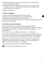
2 Safety instructions
• Follow the operating instructions.
• Improper use may result in malfunctions of the unit. This can lead to personal
injury and/or damage to property during operation of the machine. For this
reason note all remarks on installation and handling given in these instructions.
Also adhere to the safety instructions for the operation of the whole installation.
• In case of non-observance of notes or standards, specially when tampering
with and/or modifying the unit, any liability and warranty is excluded.
• The unit must be installed, connected and put into operation by a qualified
electrician trained in safety technology.
• The applicable technical standards for the corresponding application must be
complied with.
• For installation the requirements according to EN 60204 must be observed.
• In case of malfunction of the unit please contact the manufacturer. Tampering
with the unit is not allowed.
• Disconnect the unit externally before handling it. Also disconnect any
independently supplied relay load circuits.
• After setup the system has to be subjected to a complete function check.
• Use the unit only in specified environmental conditions (→ 11 Technical data).
In case of special operating conditions please contact the manufacturer.
• Use only as described below (→ 4 Functions and features).
2.1 Safety-related requirements regarding the application
It must be ensured that the safety requirements of the respective application
correspond to the requirements stated in these instructions.
Observe the following requirements:
►► Take measures to avoid metallic objects being placed on the sensing face
intentionally or unintentionally.
►► Adhere to EN 1088 for interlocking devices associated with guards.
►► Adhere to the specified operating conditions (→ 11 Technical data). Use of
the sensor in the vicinity of chemical and biological media as well as ionising
radiation is not permitted.
4
►► Adhere to the principle of normally closed operation for all external safety
circuits connected to the system.
►► In case of faults within the fail-safe sensor which result in the defined safe
state: take measures to maintain the safe state when the complete control
system continues to be operated.
►► Replace damaged units.
3 Items supplied
1 fail-safe sensor GM701S with premounted angle bracket,
UK
1 Allen key for fixing the fail-safe sensor onto the angle bracket,
1 operating instructions GM701S, ident number 701976.
If one of the above-mentioned components is missing or damaged, please contact
one of the ifm branch offices.
4 Functions and features
The fail-safe inductive sensor GM701S detects metal without contact.
Safety function SF: The safe state (output stage switched off; logic "0") is achieved
when undamping greater than or equal to the safe switch-off distance sar (→ 11
Technical data).
Also observe the notes on installation of the sensor (→ 6 Installation).
The fail-safe sensor conforms to the category 4 according to EN 954-1 (valid until
31 December 2011), Performance Level e according to EN ISO 13849-1:2008 as
well as to the requirements SIL 3 to IEC 61508 and meets SILcl 3 to IEC 62061.
Depending on the type of installation the unit corresponds to the classification
I1C40SP2 to IEC 60947-5-2 for flush installation as well as I2C40SP2 to IEC
60947-5-2 for non-flush installation (→ 6 Installation).
The fail-safe inductive sensor has been certified by TÜVNord.
The unit is suited for applications up to 5 Hz.
5
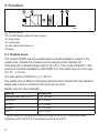
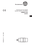
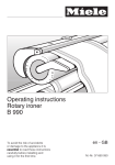
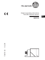
5 Function
mm
fail-safe sensor
2 x LED: Signal (yellow); Power (green)
close range
enable zone
safe switch-off distance sar
target
5.1 Enable zone
The outputs (OSSD) are only enabled when a damping target is present in the
enable zone. Outside this enable zone the outputs remain switched off.
If damped with a standard target plate of 45 x 45 x 1 mm made of FE360 (= mild
steel) and non-flush installation to IEC 60947-5-2, the enable zone is in the range
of ≤ 10 ... ≥ 15 mm.
The safe switch-off distance sar is > 30 mm.
The enable zone is different if damping elements which deviate from the standard
target plate in terms of material, form and size are used.
Enable zone for other materials*:
Material
stainless steel (304/1.4301)
AIMg3G22
AI 99 %
CuZn37
Cu
Enable zone
7.5...13.2 mm
2.0...5.8 mm
1.4...5.0 mm
2.3...6.2 mm
0.8...4.3 mm
* Typical values for damping with a reference target of 45 x 45 x 1 mm and non-flush
installation to IEC 60947-5-2 at an ambient temperature of 20°C.
6
5.2 Protection against simple defeating
The fail-safe sensor reacts to metal objects, e.g. the frame of a security door.
Other metal objects that are not intended to enable the sensor must not be
allowed to enable the fail-safe sensor, either intentionally or unintentionally.
►► Take measures to prevent metal objects, except the designated target,
from being placed on the sensing face or in the enable zone intentionally
or unintentionally.
In addition, the sensor has the following switching characteristics to make simple
defeating of its safety function more difficult:
UK
1. By slowly introducing a metallic object into the enable zone, the outputs are
immediately switched, but displayed by the LED with a delay of approx. 3 s
(→ 9.2.1 Delayed switching of the LED). By doing so, the object is generally
in the close range before the LED indication is lit. The technical instructions
concerning the restart of the installation must be observed.
2. If the metal object remains in the close zone for over approx. 2 s, the outputs
are completely disabled and no longer enabled in case of damping in the
enable zone. If the object stays in the close range for longer than approx. 5 s,
the adjustment mode is activated (→ 8.1 Activate adjustment mode).
Release of the enable zone can be carried out
•by undamping (> 30 mm) for over 2 s
•or by power off
(→ 8.3 End adjustment mode).
7
6 Installation
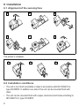
6.1 Alignment of the sensing face
1
2
3
4
5
6
The socket is rotatable:
7
8
9
6.2 Installation conditions
• The unit is non flush mountable in steel in accordance with IEC 60947-5-2,
type I2C40SP2. In addition one side of the unit can be mounted flush with
steel.
• The unit can be mounted flush with copper, aluminium and brass according to
IEC 60947-5-2, type I1C40SP2.
8
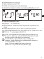
►► Ensure the unit cannot work loose.
►► Tighten captive screws with 1 Nm.
►► Limit the use of oblong holes to the initial setting.
►► Adhere to the installation conditions in accordance with the figures 1 to 3:
1
2
3
UK
7 Electrical connection
Wiring diagram → 11 Technical data
►► Disconnect power. Also disconnect any independently supplied relay load
circuits.
►► Supply voltage: Connect L+ to pin 1 and L- to pin 3 of the connector.
The nominal voltage is 24 V DC. This voltage may vary between 19.2 V and
30 V incl. 5% residual ripple to EN 61131-2.
In case of a single fault the supply voltage must not exceed 60 V DC
for over 0.2 s up to a max. value of 120 V DC. (This requires the safe
separation between power supply and transformer.)
For unit with cULus approval and the scope of validity cULus:
The device shall be supplied from an isolating transformer having a
secondary listed fuse rated either
a) max. 5 amps for voltages 0~20 Vrms (0~28.3 Vp) or
b) 100/Vp for voltages of 20~30 Vrms (28.3~42.4 Vp).
9
8 Set-up
8.1 Activate adjustment mode
For easy and reliable installation the sensor can be put in the adjustment mode.
This is done by placing a metallic
object directly in front of the sensing
face of the fail-safe sensor (close
range).
After approx. 5 s the yellow LED
0
30
mm
starts to flash: The adjustment mode
>5s
is active.
Signal
As long as this mode is active the
Power
output stages remain in the safe
state.
close range
enable zone
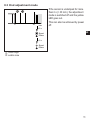
8.2 Determine the enable zone
If the sensor is in the adjustment mode, the enable zone of the sensor can be
determined by moving the damping element.
As soon as damping is carried out
in the enable zone, the yellow LED
goes out.
If the target is in the close range or in
the immediate vicinity of the enable
0
30
mm
zone, the LED starts to flash again.
Signal
Signal
Signal
Power
Power
Power
close range
enable zone
10
8.3 End adjustment mode
0
30
mm
If the sensor is undamped for more
than 2 s (> 30 mm), the adjustment
mode is switched off and the yellow
LED goes out.
This can also be achieved by power
off.
<2s
UK
Signal
Power
>2s
Signal
Power
close range
enable zone
11
9 Operation
9.1 Switching state of the outputs
9.1.1 The safe state
The safe state is when at least one of the outputs A1 and A2 (OSSD) is switched
off ( zero-current state: logic "0").
If one of the outputs A1 and A2 is switched off, the subsequent safety-related logic
unit must bring the complete system into the state defined as safe.
9.1.2 The switched state
If the damping element is in the enable zone and if there is no sensor error, both
outputs A1 and A2 (OSSD) are enabled (logic "1").
9.1.3 Output characteristics
The output characteristics are compatible with the input characteristics to
EN 61131-2 type 1 or 2:
Logic "1"
Logic "0"
≥ 15 V
≥ 11 V
≤5V
2...15 mA
15...30 mA
leakage current 0.2 mA*)
*) pull-down current typ. 30 mA
9.1.4 Cross faults
• A cross fault between both outputs (A1 and A2) is detected by the fail-safe
sensor and leads to switching off the outputs (OSSD) at the next safety
request. The outputs A1 and A2 remain switched off until the error has been
removed.
• A cross fault between one of the two outputs (A1 or A2) and the supply voltage
leads to switching off the other output (A2 or A1) in case of a safety request.
12
9.2 Operating mode
The length of the preceding undamping determines whether the yellow LED
comes on with a delay (→ 9.2.1) or without delay (→ 9.2.2) when a target moves
into the enable zone. The outputs definitely switch on without delay.
In case of undamping the outputs switch off and the yellow LED goes out without
delay.
In case of damping in the close range the outputs switch off immediately whereas
the yellow LED goes out with a delay of approx. 2 s. With the LED going out the
outputs are maintained in the safe state ("0"). Thus, switching on again in the
UK
enable zone is not possible. Enabling is done by undamping (> 30 mm) of more
than 2 s or by interrupting the voltage (→ 5.2 Protection against simple defeating).
9.2.1 Delayed switching of the LED
Undamping > 2s:
0
>3s
30
mm
If the target was away from the
sensor for more than approx. 2 s
(> 30 mm), the yellow LED goes on
with a delay of approx. 3 s in case of
damping in the enable zone.
This is also the case if the target is in
the enable zone when the voltage is
switched on.
Signal
Power
close range
enable zone
13
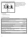
9.2.2 Switching of the LED without delay
If the target was away from the
sensor for less than 2 s (> 30 mm),
the yellow LED comes on without
delay in case of damping in the
enable zone.
Undamping > 2s:
0
≈ 0 s*)
30
mm
Signal
Power
Close range
Enable zone
*)
except for the first start-up
9.3 Response times
Response time on safety request (removal from the enable zone)
≤ 50 ms
Response time when approaching the close range
(non safety-related zone)
≤ 100 ms
Response time when approaching the enable zone (enable time)
Risk time / response time for safety-related faults
typ. 100 ms
≤ 200 ms
≤ 100 ms
Permissible dwell time in the close range
approx. 2 s
Delay time to activate the adjustment mode
(→ 8.1 Activate adjustment mode)
approx. 5 s
Dwell time in the undamped condition (≥ 30 mm) to return to the
operating mode (→ 8.3 End adjustment mode)
approx. 2 s
Simultaneity of switching on and off of the outputs in the case of a
safety request
≤ 50 ms
Duration of switch-off test pulses
≤ 1 ms
14
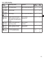
9.4 LED display
LED
status
Operating status
Outputs
Signal
Power
no voltage supply
both outputs switched off
Signal
Power
undervoltage
Signal
Power
overvoltage
Signal
Power
both outputs
switched off
0
0
Signal
Power
target outside the enable
zone (operating mode) or in
the enable zone (adjustment
mode)
target in the enable zone
(operating mode)
both outputs
enabled
1
1
Signal
Power
target outside the enable
zone (adjustment mode)
both outputs
switched off
0
0
Signal
Power
internal or external fault
(→ 12 Troubleshooting)
0
0
1
0
1
0
both outputs switched off
A1
A2
(OSSD) OSSD
0
0
0
0
0
0
UK
15
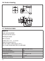
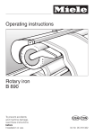
10 Scale drawing
66
40
34
M12 x1
40
17
5,4
5,4
30
20
10
8,5
LED
33
6
46
61
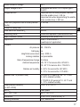
11 Technical data
GM701S
GIMC-4030-US/2OSSD
Fail-safe inductive sensor
Rectangular plastic
M12 connector
Enable zone: ≤ 10 ... ≥ ± 15 mm
Meets the requirements of:
EN ISO 13849-1: 2008 category 4 PL e,
SIL 3 to IEC 61508: 2000, SILcl 3 to IEC 62061
Operating voltage
Short-circuit protection
Reverse polarity protection
Voltage drop
Current consumption
Outputs A1, A2 (OSSD)
16
24 V DC (19.2...30 V)
yes
yes
< 2.5 V @ 100 mA
< 15 mA
PNP
Rated insulation voltage
Output voltage at 24 V
Response time
Risk time (response time for safety-related
faults)
Power-on delay time
Safe switch-off distance sar
Operating mode
EMC / vibration, shock
Application
30 V
compatible with EN 61131-2 inputs type 1,
2 and 3
response time on safety request (removal
from the enable zone): ≤ 50 ms
response time when approaching the enable
zone (enable time): ≤ 200 ms
≤ 100 ms
5s
30 mm
continuous operation (maintenance-free)
according to IEC 60947-5-2
class C to EN 60654-1
(weatherproof application)
UK
Climate
Air pressure
Salt spray
Height above sea level
Ionising radiation
Rate of temperature change
Ambient temperature
80...106 kPa
no
max. 2000 m
not permissible
0,5 K/min
-25..70 °C for service life ≤ 87 600 h
10...40 °C for service life ≤ 175 200 h
Relative air humidity 5...95 % for service life ≤ 87 600 h
5...70 % for service life ≤ 175 200 h
Mission time TM (mission time)
Safety-related reliability
(to IEC 61508)
MTTFD
DC / CCF / Cat.
Protection
Housing materials
≤ 87 600 h (10 years) at -25...70 °C and
5...95 % relative humidity
≤ 175 200 h (20 years) at 10...40 °C and
5...70 % relative humidity
PFH < 2.5 x 10⁻⁹/ h
1992 years
99 % / 100 % / 4
IP 65 / IP 67 (to EN 60529), III
PPE; diecast zinc
17
Display
Connection
Wiring
LED yellow (Signal); LED green (Power)
M12 connector, gold-plated contacts
Evaluation unit or PLC
Core colours:
BK:black
BN:brown
BU:blue
WH:white
Comments:
Unless stated otherwise, all data refer to the 45 x 45 x 1 mm reference target plate to
IEC 60947-5-2 (FE360 = mild steel) over the whole temperature range.
18
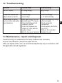
12 Troubleshooting
Problem
Possible cause
Troubleshooting
No LED display
No voltage supply
Apply voltage
Power LED flashes and
sensor does not switch
•Undervoltage
•Overvoltage
Correct the voltage
(→ 11 Technical data)
Sensor does not switch,
not even after undamping
and redamping
Sensor was brought into the
safe state (logic "0"). Cause:
•Cross fault between both
outputs A1 and A2
•Cross fault between one
output (A1 or A2) and the
supply voltage
•Error in the sensor detected
•Switch the operating voltage
off and on again
UK
•Check wiring and
connections
•Check external electronics
(e.g. PLC)
•Remove the cross fault
•Replace the unit
13 Maintenance, repair and disposal
If used correctly no maintenance and repair measures are necessary.
Only the manufacturer is allowed to repair the unit.
After use dispose of the unit in an environmentally friendly way in accordance with
the applicable national regulations.
19
14 Approvals / standards
The following standards and directives have been applied:
• 2006/42/EC European Machinery Directive
• 2004/108/EC EMC Directive
• EN ISO 13849-1 PL e (2008) Safety of machinery - Safety-related parts of
control systems
• IEC 60947-5-2 (2007) Low-voltage switchgear and controlgear: Control circuit
devices and switching elements - Proximity switches
• IEC 61508 (2000)
• IEC 62061 (2005)
• UL 508
20
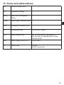
15 Terms and abbreviations
CCF
Common Cause Failure
DC
Diagnostic Coverage
MTTFD
Mean Time To Dangerous
Failure
OSSD
Output Signal Switching Device
PFH
Probability of failure per Hour
PL
Performance Level
PL to EN ISO 13849-1
SIL
Safety Integrity Level
SILcl
Safety Integrity LevelClaim Limit
SIL 1-4 to IEC 61508. The higher the
SIL, the lower the probability that a safety
function will fail.
to IEC 62061
TM
Mission Time
UK
Lifetime
(= max. service life)
21