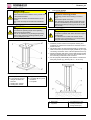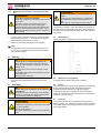
1
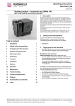
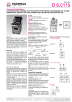
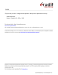
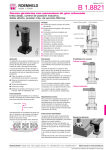
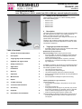
Operating instructions
BA M4101_EN
Issue 09-12
Lifting module Basic
max. lifting force 1,000 N, stroke from 200 to 600 mm, manual-hydraulic version
1
Validity of the documentation
These operating instructions are valid for the lifting module
basic of the following types:
• 8910-01-20-H
• 8910-01-30-H
• 8910-01-40-H
• 8910-01-50-H
• 8910-01-60-H
2
Description
The stroke movement is obtained by a hydro-mechanical lifting
jack with single-lever actuation, with oil being pumped by
means of a piston pump into a plunger cylinder.
For lowering the oil returns by the weight of the load from the
cylinder back to the reservoir.
The lifting units are ideal for height adjustment of tables, demonstration objects and similar equipments as well as for medical treatment equipments.
3
Target group of this document
•
Table of contents
1
Validity of the documentation
1
2
Description
1
3
Target group of this document
1
4
Symbols and signal words
2
5
Safety instructions
2
6
Application
3
7
Installation
3
8
Start up
5
9
Operation
5
10
Maintenance
6
11
Repair
7
12
Trouble shooting
7
13
Technical characteristics
7
14
Accessory
7
15
Disposal
8
16
Declaration of manufacture
8
Specialists, fitters and set-up men of machines and installations with hydraulic expert knowledge.
Qualification of the personnel
Expert knowledge means that the personnel must
• be in the position to read and completely understand technical specifications such as circuit diagrams and productspecific drawing documents,
• have expert knowledge (electric, hydraulic, pneumatic
knowledge, etc.) of function and design of the corresponding components.
An expert is somebody who has due to its professional education and experiences sufficient knowledge and is familiar with
the relevant regulations so that he
• can judge the entrusted works,
• can recognize the possible dangers,
• can take the required measures to eliminate dangers,
• knows the acknowledged standards, rules and guidelines of
the technology.
• has the required knowledge for repair and mounting.
Further qualification / age restrictions
The personnel must:
• be physically and mentally in the position to do the work
required
• be at least 18 years old
Young people under the age of 18 years may only work at
the product supervised by a specialist, and if it is required
for the vocational training (minimum age of 16 years),
• protect the working area as per the existing rules
The responsibility for different activities at the product have to
be clearly defined and kept. Unclear competences are a
security risk.
Römheld GmbH • Postfach 1253 • 35317 Laubach • Germany • Tel.: +49 (0)6405 / 89-0 • Fax: +49 (0)6405 / 89-211 • www.roemheld.de
Subject to change without notice! Translation of the original German document
1/8
Operating instructions
BA M4101_EN
4
Symbols and signal words
DANGER
Danger of life / heavy health damages
Stands for an imminent danger.
If it is not avoided, death or very severe injuries will
result.
WARNING
Person damage
Stands for a possibly dangerous situation.
If it is not avoided, death or very severe injuries will
result.
CAUTION
Easy injuries / property damage
Stands for a possibly dangerous situation.
If it is not avoided, minor injuries or material damages will result.
Hazardous to the environment
The symbol stands for important information for the
proper handling with materials that are hazardous to
the environment.
Ignoring these notes can lead to heavy damages to
the environment.
Mandatory sign!
The symbol stands for important information, necessary protection equipment, etc.
5.2
General safety tips
WARNING
Poisoning due to contact with hydraulic oil!
Wear, damage of the seals, ageing and incorrect
mounting of the seal kit by the operator can lead to
escapes of oil.
Incorrect connection can lead to escapes of oil at
the ports.
For handling with hydraulic oil consider the material
safety data sheet.
Wear protection equipment.
WARNING
Injury by high-pressure injection (squirting out
of hydraulic oil under high pressure)!
Improper connection and use can lead to escapes of
oil under high pressure at the seals.
Mounting or dismounting of the element must only
be made in depressurised mode.
Fixing has to be made in an appropriate way.
WARNING
Injury by crushing!
Components of the product make a movement while
they are in operation.
This can cause injuries.
Keep parts of the body and items out of the working
area!
CAUTION
Note
This symbol stands for tips for users or especially useful
information. This is no signal word for a dangerous or
harmful situation.
5
Safety instructions
5.1
Basic information
The operating instructions serve for information and avoidance
of dangers when installing the products into the machine as
well as information and references for transport, storage and
maintenance.
Only in strict compliance with these operating instructions,
accidents and property damages can be avoided as well as
trouble-free operation of the products can be guaranteed.
Furthermore, the consideration of the operating instructions will
result in:
• reduced down times and repair costs,
• increased service life of the products.
Note
These operating instructions are not a replacement for
the operating instructions of the entire machine.
Damage of components!
Side loads and forced conditions on the product lead
to the premature failure.
Avoid forced conditions (overdetermination) of the
product.
Max. forces and torques see technical characteristics.
CAUTION
Damage of components!
The admissible performance data of the product,
see chapter "Technical characteristics", may not be
exceeded.
CAUTION
Damage of components!
With hydraulic pressure very high forces are
generated.
The fixture or machine must be in the position to
compensate these forces.
2/8
Operating instructions
BA M4101_EN
CAUTION
Damage of components!
For cleaning / disinfection the plunger should be
retracted to avoid degreasing of the plunger.
For cleaning / disinfection the environment temperature and the temperature of the cleaning agent of
max. 70°C must not be exceeded.
The application of cold water immediately after
cleaning / disinfection is not admissible.
CAUTION
Damage of components!
The product must not be cleaned with
• vacuum steam procedure, steam ray or highpressure cleaner
• abrasives, scouring pads or other blunting materials
• cleaning agents with corrosive or caustic ingredients
• organic solvents as halogen or aromatic hydrocarbons and ketones (cellulose thinner, acetone, etc.), since this can damage the product.
Note - qualification of the user
All works may only be effected by qualified personnel
familiar with the handling of hydraulic components.
5.3
Warning
WARNING
Injuries due to misuse, incorrect operation or
abuse!
Injuries can occur if the product is not used within
the intended use and the technical performance
data.
Before start up, read the operating instructions!
5.4
Personal protective equipment
For works at and with the product,
wear safety goggles!
For works at and with the product,
wear protective gloves!
6.2
Intended use
The products are used as components in medical engineering,
in trade fair construction and for office and communication
furniture in the commercial sector. They are used to produce a
vertical, linear movement and / or force.
Furthermore the following belongs to possible uses:
• Use within the capacity indicated in the technical characteristics (see data sheet).
• Use as per operating instructions.
• Compliance with service intervals.
• Qualified and trained personnel for the corresponding activities.
• Mounting of spare parts only with the same specifications
as the original part.
6.3
WARNING
Injuries, material damages or malfunctions!
Do not modify the product!
The use of these products is not admitted:
• For domestic use.
• On pallets or machine tool tables in primary shaping and
metal forming machine tools.
• If due to vibrations or other physical / chemical effects damages of the products or seals can be caused.
• In environments, that are used to change the characteristics
of the material (magnetising, radiation, photochemical procedures, etc.).
• In areas for which special guidelines apply, especially installations and machines:
- For the use on fun fairs and in leisure parks.
- In environments for which special hygene regulations
are valid
- For military purposes.
- In mines.
- In explosive and aggressive environments (e.g. ATEX).
- In the aerospace industry.
- For passenger transport.
Special solutions are available on request!
7
7.1
For works at and with the product,
wear safety shoes!
6
Application
6.1
Principal use
• Industrial assembly working places
• Height adjustment of assembly working places in workshops
• Maintenance works
• Assembly fixtures
• Adjusting systems in supply processes of mid-sized objects
• Handling systems for product packing and transfer
Misapplication
Installation
Design
WARNING
Injury by falling parts!
Keep hands and other parts of the body out of the
working area.
Wear personal protection equipment!
CAUTION
Damage of components!
Some product types have a considerable weight.
These have to be secured against working free
during transport.
Weight specifications see chapter "Technical characteristics".
3/8
Operating instructions
BA M4101_EN
7.2
CAUTION
Fixing of the product
WARNING
Damage of components!
Side loads and forced conditions on the product lead
to the premature failure.
Avoid forced conditions (overdetermination) of the
product.
Max. forces and torques see technical characteristics.
Injury due to overturning product!
Overturning product due to missing or incorrect
fixing!
Fasten bottom plate on the floor.
When introducing torques within the load limit (see
technical characteristics) we recommend to use an
additional base plate (accessory) and to secure this
plate correctly.
CAUTION
Damage of components!
The maximum operating torque at the operating
shaft must not be exceeded.
This can be achieved e.g. by limiting the operating
stroke of the customer's operating element (hand
lever or pedal) by the floor.
CAUTION
Damage of components!
Foot pedal is pressed down below the lower edge of
the base plate.
The customer has to make sure that this will be
prevented by the concrete floor or a corresponding
base plate connecting construction.
1. Install the product so that for the required cleaning and
maintenance works there is all around a clearance zone of
at least 700 mm.
2. The product has to be mounted horizontally on a plane and
solid concrete floor (concrete strength grade B 25) or a rigid
connecting construction of the customer (flatness 0.20 mm).
3. Fasten the bottom plate of the product with hexagon socket
head cap screws ISO 4762 - M10 onto the concrete floor or
the connecting construction of the customer.
4. For this purpose professionally insert into the concrete floor
heavy-duty dowels (e.g. Fischer part-no.: SL M-10 N).
Figure 1: Components
a Base plate
a1 Four holes (Ø 10.5) for
fixing at the base construction
b Guiding tube, exterior
d Guiding tube, interior
e Top plate
a1 Four holes (Ø 10.5) to fix
the fixture
f Foot pedal
Figure 2: Principle of fixing
a
e
Base plate
Top plate
g
h
Concrete floor or connecting construction
Fixing screws (4x)
4/8
Operating instructions
BA M4101_EN
7.3
Mounting of the customer's connecting construction
WARNING
Injury due to overturning product!
Overturning product due to eccentric load provided
by the user!
The centre of gravity of the user's load must be
within the 4 fixing screws of the bottom plate.
When introducing torques within the load limit (see
technical characteristics) we recommend to use an
additional base plate (accessory) and to secure this
plate correctly.
1. For fixing of the customer's connecting construction there
are 4 bore holes (for M10 - ∅ 10.5 mm ) at the top plate.
All provided bore holes have to be used!
2. Fasten the connecting construction at the top plate.
WARNING
Injuries due to misuse, incorrect operation or
abuse!
Injuries can occur if the product is not used within
the intended use and the technical performance
data.
Before start up, read the operating instructions!
The operator is obliged to report immediately any changes at
the product that may affect the safety to the safety expert or to
the person who is responsible for safety and to stop operating
the product.
9.1
Working place
The working place is designed in front of the lifting module.
Note
Dangers due to the connecting construction of the customer, as e.g. squeezing points have to be excluded by
the customer's design.
8
Start up
WARNING
Poisoning due to contact with hydraulic oil!
Wear, damage of the seals, ageing and incorrect
mounting of the seal kit by the operator can lead to
escapes of oil.
Incorrect connection can lead to escapes of oil at
the ports.
For handling with hydraulic oil consider the material
safety data sheet.
Wear protection equipment.
1. Check tight seat (check tightening torque of the fixing
screws).
9
Operation
WARNING
Injuries due to non-compliance of the operating
instructions!
The product may only be operated, if the operating
instructions - especially the chapter "Safety instructions" have been read and understood.
WARNING
Injury by crushing!
Components of the product make a movement while
they are in operation.
This can cause injuries.
Keep parts of the body and items out of the working
area!
Figure 3: working place
9.2
Behaviour in an emergency
In emergencies the product may not be operated.
9.3
Lifting
The stroke movement is produced by the internal, hermeticallysealed, hydraulic lifting jack with foot pedal with oil being
pumped by means of a piston into a plunger cylinder.
To lift the top plate, the foot pedal has to be depressed by
approx. 40° several times. The pedal returns to its off-position
by means of a return spring.
9.4
Lowering
To lower the top plate, the foot pedal has to be pressed upwards by approx. 10°. Thereby the oil returns due to the weight
of the user's load from the plunger cylinder into the reservoir,
the top plate lowers.
5/8
Operating instructions
BA M4101_EN
10.4
10 Maintenance
10.1 Plan for maintenance
Maintenance works
Interval
Cleaning, visual check of
daily
the lifting module and inspection of the guide unit
Control of the fixing screws, half-yearly
retighten if required.
checks
Control of the guide unit
Check smooth running with
yearly
little load over the entire
stroke range
Check smooth running with
yearly
load over the entire stroke
range
Check the check valve of
yearly
the internal lifting jack with
load
Revision by the manufacafter 50,000
turer (recommendation)
cycles (lifting
and lowering)
Repair
in case of
damages
WARNING
Injury due to a lifting or lowering movement!
Before cleaning switch off power supply.
by...
operator
expert
expert
•
•
•
expert
expert
ROEMHELD
service staff
Check all fixing screws of the lifting module, retighten if
required.
Check all cable fixings and fittings, retighten if required.
Check the wear of the guide unit based on the guiding
clearance. If the clearance exceeds 0.5 mm, the guiding
elements have to be exchanged. (See chapter repair).
10.5 Yearly checks
To maintain the product in a safe condition and ready for operation, the function safety of the internal lifting jack has to be
checked annually by an expert (see maintenance schedule).
10.5.1
ROEMHELD
service staff
CAUTION
Cleaning
WARNING
Danger of injury due to a lifting or lowering
movement!
Do not reach into the stroke area during the lifting or
lowering movement.
•
•
•
Press the foot pedal upwards until the top plate is completely lowered.
Fix the test weight at the top plate (10% of the nominal
load).
Depress the foot pedal several times until the top plate is
completely lifted.
Press the foot pedal upwards until the top plate is completely lowered.
The following cleaning works have to be effected daily at the
mechanical components.
•
1. Clean with cleaning clothes or cleaning rags.
2. Slightly lubricate the metallic components (plates, guides,
etc.).
10.5.2
10.3
Damage of components!
If smooth running of the product does not work perfectly, even if only partial stroke ranges are affected,
the product must no longer be used.
Observe the checking intervals.
Daily checks
Danger of injury due to a lifting or lowering
movement!
Do not reach into the stroke area during the lifting or
lowering movement.
Visual check of the lifting module
Check the guide unit for damages and possible running
marks, repair if required.
Check smooth running of the product with load
over the entire stroke range
CAUTION
WARNING
•
•
Check smooth running of the product with little
load over the entire stroke range
Damage of components!
If smooth running of the product does not work perfectly, even if only partial stroke ranges are affected,
the product must no longer be used.
Observe the checking intervals.
Note
Pay attention to the qualification of the personnel.
10.2
Half-yearly checks
•
•
•
•
Press the foot pedal upwards until the top plate is completely lowered.
Fix the test weight at the top plate (nominal load).
Depress the foot pedal several times until the top plate is
completely lifted.
Press the foot pedal upwards until the top plate is completely lowered.
6/8
Operating instructions
BA M4101_EN
10.5.3
Check the check valve of the internal lifting jack
with load
Note
If the top plate of the product lowers independently, it
may no longer be operated!
•
•
•
•
Querkräfte
Press the foot pedal upwards until the top plate is completely lowered.
Fix the test weight at the top plate (nominal load).
Depress the foot pedal several times until the top plate is
completely lifted.
Top plate may not lower independently
11 Repair
Note
Repair works, as e.g. the change of the interior lifting
jack may only be effected by the ROEMHELD service
technicians.
12 Trouble shooting
CAUTION
Damage of components!
All works only to be effected by ROEMHELD service
staff.
Trouble
Top plate does not
lift or lower after
the operation of
the foot pedal
Top plate lowers
without operation
of the foot pedal
Cause
Internal lifting jack
defect
Remedy
Replace internal
lifting jack
Internal lifting jack
defect
Replace internal
lifting jack
13 Technical characteristics
Hubkr aft (F)
Max. lifting force
Stroke
Function
Operation
Lifting profile
Top and bottom plate
1000 N
200 … 600 mm
Manual-hydraulic
Foot pedal
Aluminium, colourless anodised
aluminium, black anodised
Type
Number of
operations
Weight
Stroke
8910-01-20-H
8910-01-30-H
8910-01-40-H
8910-01-50-H
8910-01-60-H
16
25
33
41
50
9.5 kg
10 kg
11.5 kg
13 kg
14.5 kg
200 mm
300 mm
400 mm
500 mm
600 mm
Abb. 4:
Max. load torque Mz
Max. load torque Mx or My
50 Nm
100 Nm
Note
In the case of eccentric loads, it is recommended to compensate these by counterweights. In off-position the indicated maximum torques may occur.
The forces and torques have to be considered by the
operator. During the lifting motion only 50% of the maximum values are admitted.
Tightening torques
The tightening torques for the fixing screws of the customer's
connecting construction are to be taken from the VDI guideline
2230.
Emissions
The A valued continuous sound level of the lifting module is
less than 75 dB(A) in operation.
14 Accessory
Base plate for increased stability
Part-no.
6311-412
Data sheet
M 8.100
Further accessories
M 8.110, M 8.130, M 8.131
7/8
Operating instructions
BA M4101_EN
15 Disposal
Hazardous to the environment
Due to possible environmental pollution, the individual components must be disposed only by an
authorised expert company.
The individual materials have to be disposed as per the existing
regulations and directives as well as the environmental conditions.
Special attention has to be drawn to the disposal of components with residual portions of hydraulic fluids. The instructions
for the disposal at the material safety data sheet have to be
considered.
For the disposal of electrical and electronic components (e.g.
stroke measuring systems, proximity switches, etc.) countryspecific legal regulations and specifications have to be kept.
16 Declaration of manufacture
Manufacturer
Römheld GmbH Friedrichshütte
Römheldstraße 1-5
35321 Laubach, Germany
Tel.: +49 (0) 64 05 / 89-0
Fax: +49 (0) 64 05 / 89-211
E-mail: [email protected]
www.roemheld.com
16.1 Validity of the documentation
These operating instructions are valid for the lifting module
basic of the following types:
• 8910-01-20-H
• 8910-01-30-H
• 8910-01-40-H
• 8910-01-50-H
• 8910-01-60-H
They are designed and manufactured in line with the relevant
versions of the directives 2006/42/EC (EC MSRL) and in compliance with the valid technical rules and standards.
In accordance with EC-MSRL and EN 982, these products are
components that are not yet ready for use and are exclusively
designed for the installation in a machine, a fixture or a plant.
According to the pressure equipment directives the products
are not to be classified as pressure reservoirs but as hydraulic
placing devices, since pressure is not the essential factor for
the design, but the strength, the inherent stability and solidity
with regard to static or dynamic operating stress.
The products may only be put into operation after it was assessed that the incomplete machine/machine, in which the
product shall be installed, corresponds to the machinery directives (2006/42/EC).
16.2 List of the applied standards
2001/95/EC, General product safety
92/58/EEC, Minimum requirements for the provision of safety
and/or health signs at work
89/391/EEC, Introduction of measures to encourage improvements in the safety and health of workers at work
CE
89/655/EEC, Minimum safety and health requirements for the
use by workers of personal protective equipment at the workplace
Operating safety regulations (BetrSichV) for the transposal
of the directive on the introduction of measures to encourage improvements in the safety and health of workers at
work. (German implementation of the Work Equipment Directive 89/655/EEC)
Product Safety Act - PSG; November 2011
DIN EN ISO 12100, 2011-03, Safety of machinery; Basic concepts, General principles for design (replacement for part 1
and 2)
DIN EN ISO 13857; 2008-06, Safety of machinery - Safety
distances to prevent hazard zones being reached by upper
and lower limbs. (replaces: DIN EN 294)
DIN EN 349, 2008-09, Safety of machinery. Minimum gaps to
avoid crushing of parts of the human body
DIN EN 614-1 a. 2, 2009-06, Safety of machinery - Ergonomic
design principles
DIN EN 1494; 2009-05, Mobile or movable jacks and associated lifting equipment
DIN EN 626-1, 2008-09, Safety of machinery - Reduction of
risks to health from hazardous substances emitted by machinery
DIN EN ISO 4413, 2011-04, Hydraulic fluid power - General
rules and safety requirements for systems and their components
DIN EN 1037, 2008-11, safety of machinery - prevention of
unexpected start-up.
DIN EN 81714-2, 2007-08, Design of graphical symbols for use
in the technical documentation of products
Responsible person for the documentation:
Dipl.-Ing. (FH) Jürgen Niesner, Tel.: +49(0)6405 89-0.
Römheld GmbH
Friedrichshütte
Laubach, 10.09.2012
The manufacturer commits to transmit the special documents of
the products to state authorities on request.
The technical documentation as per appendix VII part B was
prepared for the products.
8/8