1
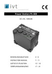
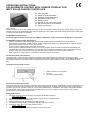
OPERATING INSTRUCTIONS
SOLAR REMOTE CONTROL WITH COMFORT DISPLAY FOR
MPPT SOLAR CHARGE CONTROLLER
;
;
;
;
;
;
;
;
Easy operation
Display of solar parameters
Display of charge parameters
Integrated real time clock
Display of date
Remote control of the main module
SD card function for PC evaluation
Plug & Play function
Dear customer,
Thank you very much for the trust you have placed in us. You have bought a remote control with comfort display for the most
effective, compact and reliable MPPT solar charge controller in its class. Please read these operating instructions carefully prior
to putting your solar system into operation.
ATTENTION!!! Important Note!!!
The device supports the SD card format up to 2GB only. Adaptation of other formats such as Mini-SD is not possible.
ATTENTION!!! Important Safety Information!!!
- The use of the device under unfavourable environmental conditions must be avoided under all circumstances.
Unfavourable environmental conditions include: ambient temperatures above 50° C, flammable gases, solvents, vapours,
dust, relative humidity in excess of 80 %, and moisture.
The device must only be operated in dry and closed rooms.
- If there is reason to believe that safe operation is no longer possible, the device must be switched off immediately and
secured against unintentional operation. A safe operation can no longer be assumed if the device shows visible signs of
damage, in the event of transportation damage, after the device has been stored under adverse conditions.
Make sure that no foreign bodies or contamination can get into the SD card opening.
General description of the functions
The solar remote control with comfort display for the MPPT solar charge controller provides visual control of the charge
parameters during running operation and the remote control of the MPPT solar charge controller. The integrated display of date
and real time and the SD card support make it possible to perform a PC-based evaluation of the working parameters at any
time.
Connection and operating elements
1.
2.
3.
Cable connection to main module
CD card
Control key (Standby/Date)
Connection and start-up procedure
The remote control must be connected to the MPPT solar charge controller using the supplied cable. As soon as both parts are
connected, the remote control is ready for use. The device is supplied over the MPPT solar charge controller. Make sure that
the MPPT solar charge controller is ready for use and that the lead battery is available for main supply. During initial operation
the internal clock of the remote control must be set. Afterwards it is no more necessary, as the remote control contains a
storage battery to supply the timer with current.
Setting date and time
1. Search the menu by means of the “SET“ key until the actual date is indicated.
Date: 2007.08.25
2. Confirm the “Standby/Date“ key Æ You reach the change mode to indicate the year.
3. Set the year by means of the “SET“ key.
4. Proceed analogously with the indication of month and day.
5. You leave the change mode by pushing the “Standby/Date“ key once more
6. Now use the “SET“ key to turn to the indication of time
Time: 13:30:50
7. Proceed analogously to the setting of the date in order to set the time.
Standby operation
If the input power of the MPPT solar charge controller is too low (below 5 V DC) and the load output is passive, the MPPT solar
charge controller turns into standby mode after approx. 3 seconds. Simultaneously, the display of the remote control turns off. A
“wakeup“ is generated, if the input voltage exceeds approx. 9 V DC, the key for the connection of the load output has been
pushed, or the “standby/date” key of the remote control has been pushed.
Display of operating parameters for solar module
Us: 11.3 Is: 01.2
The display indicates the voltage of the solar module input (Us) in volts and the related solar current (Is) in amperes. The
example above shows a voltage of 11.3 V and the current of 1.2 A. This corresponds to a current solar capacity of 13.56 Watt.
Display of operating parameters for battery
U1: 12.3 I1: 01.2
The display indicates the voltage of the battery terminals (Us) in volts and the related charge current (Is) in amperes. The
example above shows a voltage of 12.3 V and the current of 1.2 A for accu 1. The 3A solar charge controller provides the
connection of two independent batteries. Thus, the display also indicates the parameters of accu 2 (U2 and I2).
Attention! If a load is switched on, voltage and current cannot be indicated exactly. We recommend to switch off the load for at
least 3-4 seconds to determine the correct load parameters.
Battery status display
MPPT solar charge
controller
Red LED
Yellow LED
Green LED
Remote control
Meaning
BATT1: < █ █
>
BATT1: < █ █ █ █
>
BATT1: < █ █ █ █ █ █ >
Max. discharge voltage of the battery has been reached.
Deep discharge is active.
Battery is charging
Battery is fully charged. Service mode is active.
SD card
If required, the data can be written in real time on a SD card. This creates a TXT-file, which can be imported into a spreadsheet
routine and be evaluated there. The commercial Flash memory cards in SD format, no Mini-SD or similar, up to 2GB are
supported. If a card is recognized after plugging it in, the display indicates the following message:
SD CARD IN SOCKET
If no SD card has been plugged or if a card has been not recognized, the display shows the following message:
SOCKET IS EMPTY
The SD card must be formated with FAT16.
Replacement and disposal of storage battery CR 2032
A storage battery is used to supply the timer. Proceed as follows to replace it:
A suitable tool, e.g. slotted screwdriver must be installed between the lower part of the body and the lower edge of the cable
socket to the main module. The lower and upper part of the body can now be separated by slightly rotating the screwdriver. The
body had only been clicked and not glued or screwed. After having opened the body, remove the printed board carefully from
the body and replace the storage battery. Observe the correct polarity when inserting the battery.
Do not dispose of empty batteries/accus together with normal household waste. Drop the batteries/accus off at a collection
centre or your public utilities.
Technical specifications
Typ. voltage:
10 V DC
Typ. consumption of own current active:
15mA
Typ. consumption of own current standby: < 1mA
Updating of display:
in approx. 3-second steps
Storage battery type:
CR2032
Connection cable length:
3m
Dimensions:
100 x 60 x 28 mm
Weight:
100 g
Environmental protection notice
At the end of its useful life, this product must not be disposed of together with normal household waste, but has to be dropped off
at a collection centre for the recycling of electrical and electronic devices. This is indicated by the symbol on the product, on the
instruction manual or on the packaging.
The materials of which this product is made are recyclable pursuant to their labeling. With the reuse, the recycling of the
materials or other forms of scrap usage you are making an important contribution to the protection of the environment. Please
ask your local administration office for the appropriate disposal center.
Technical specifications subject to change. We assume no liability for typographical errors. 09/2007
IVT Innovative Versorgungs-Technik GmbH, Dienhof 14, D-92242 Hirschau
Phone: 09622-719910, Fax: 09622-7199120; [email protected]; www.IVT-Hirschau.de