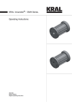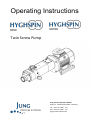
1
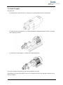
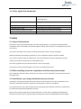
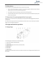
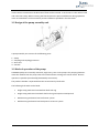
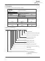
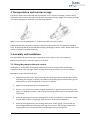
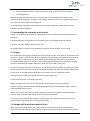
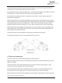
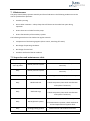
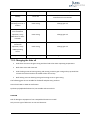
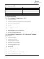
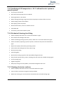
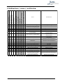
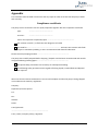
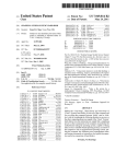
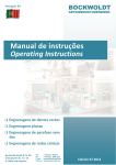
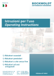
Operating Instructions Twin Screw Pump Jung Process Systems GmbH Auweg 2 · 25495 Kummerfeld · Germany Tel.: +49 4101 7958 - 140 Fax: +49 4101 7958 - 142 jung-process-systems.de Index 1 General information .......................................................................................................................................... 1 1.1 Information about these operating instructions .................................................................................... 1 1.2 Intended use ........................................................................................................................................... 1 1.3 Scope of supply....................................................................................................................................... 2 1.4. Other applicable documents ................................................................................................................. 3 2 Safety ................................................................................................................................................................. 3 2.1 General information ............................................................................................................................... 3 2.2 Risks resulting from non-compliance with the safety instructions ........................................................ 3 2.3 Installation, operating and maintenance personnel .............................................................................. 3 2.4 Safety devices ......................................................................................................................................... 4 2.5 Conversion of the system/pump and use of spare parts ....................................................................... 4 3 Design and mode of operation .......................................................................................................................... 4 3.1 Pump design ........................................................................................................................................... 4 3.2 Design of the pump assembly unit ......................................................................................................... 5 3.3 Mode of operation of the pump ............................................................................................................ 5 3.4 Nameplate .............................................................................................................................................. 6 4 Transportation and interim storage .................................................................................................................. 7 5 Erection and installation.................................................................................................................................... 7 5.1 Fitting the pump on the unit console ..................................................................................................... 7 5.2 Assembling the assembly unit console................................................................................................... 8 5.3 Piping ...................................................................................................................................................... 8 5.4 Pumps with flushed mechanical seals .................................................................................................... 8 5.5 Electrical connection .............................................................................................................................. 9 6 Pump/system operation .................................................................................................................................. 10 6.1 Initial startup ........................................................................................................................................ 10 6.2 Shutting down ...................................................................................................................................... 10 6.3 Restarting ............................................................................................................................................. 10 7 Servicing and cleaning ..................................................................................................................................... 10 7.1 Maintenance......................................................................................................................................... 11 7.2 Inspection and maintenance table ....................................................................................................... 11 7.3 Cleaning/sterilising ............................................................................................................................... 13 8 Malfunctions / causes / rectification............................................................................................................... 15 9 Servicing, spare parts, accessories .................................................................................................................. 16 Appendix............................................................................................................................................................. 17 Declaration of Conformity .................................................................................................................................. 18 In terms of CE Machine’s Directive 2006/42/EG, Appendix II A .................................................................... 18 Declaration of Incorporation .............................................................................................................................. 18 In terms of CE Machine’s Directive 2006/42/EG, Appendix II B..................................................................... 18 1 General information 1.1 Information about these operating instructions These operating instructions contain basic instructions for installation, operation and servicing. They must in all cases be read before installation and initial startup by the responsible user/operator and must always be available at the installation location since no liability will be assumed for any damage or operational malfunctions arising from non-compliance with these operating instructions. 1.2 Intended use The pump is solely to be used for the pumping of the media agreed in the order datasheet. Any other application that goes beyond the intended use, or any conversion of the pump without written agreement with the manufacturer, shall be deemed to be not in accordance with the intended use. The pump may only be started up for the first time if it has been ensured that all safety devices are completely fitted and functional. In areas subject to risk of explosion only pumps designed to the relevant explosion-proof specification may be used. Intended use also covers compliance with the conditions of operation, servicing and maintenance specified by the manufacturer. The pump is only capable of dry running for a short time. The occurrence of dry running phases should therefore be avoided or agreed in advance with the manufacturer. The pump is only to be put into operation when filled with medium to be pumped. Before starting up ensure that: - the valves on the inlet side open completely (to avoid cavitation) - the valves on the outlet side open completely (to avoid exceeding the permitted differential pressure of the pump) - outlet-side safety measures are taken (e.g. safety valve) to protect the pump from nonpermitted excess pressure Guards that protect against contact with hot, cold and moving parts must not be removed during operation 1 HYGHSPIN, edition 01.2015 1.3 Scope of supply The pump can: - be ordered with a free shaft end, i.e. the pump is supplied without motor or baseplate - be ordered as an assembled unit, i.e. ready-assembled on baseplate with drive motor, coupling and coupling protection - be ordered as a block design, i.e. pump with flange-fitted motor The scope of supply corresponds to the scope specified in the order. Immediately on receipt of the pump, ensure it is complete and report any damage or defects to the delivery company. 2 HYGHSPIN, edition 01.2015 1.4. Other applicable documents Pump datasheet Technical data, conditions for use, performance and operating limits Dimensional drawing Operating limits Designation of components and connections Spare parts lists Supplementary sheet Disassembly/assembly instructions Vendor documentation Spare parts ordering Mechanical seal system technical data Disassembly and assembly of the pump Technical documentation for vendor parts 2 Safety 2.1 General information The pump is only to be operated when in perfect working order. It is also only to be operated in accordance with its intended use and with regard to safety and risk aspects in compliance with these instructions. Instructions attached to the machine shall be maintained in their entirety and legibly. Working methods that endanger personnel or non-involved third parties shall be avoided. In the event of safety-relevant malfunctions, the pump shall be shut down immediately and the malfunction shall be rectified by the responsible person. The safety regulations of the relevant operator country also apply. The pump has to be protected against access by non-qualified personnel. 2.2 Risks resulting from non-compliance with the safety instructions Non-compliance with the safety instructions can cause a risk to individuals, the environment and to the pump itself. 2.3 Installation, operating and maintenance personnel Installation, operating and maintenance personnel are those persons who are responsible for the shipment, assembly, installation, operation, cleaning and correction of problems. The operator must ensure that all maintenance, operating and installation activities are performed by authorised and properly qualified personnel. Work on the system should only be performed when it is shut down. Immediately following the conclusion of such work, all safety and protective devices must be refitted/made functional again. 3 HYGHSPIN, edition 01.2015 2.4 Safety devices Ensure provision of the following safety devices and their functionality: • For hot, cold and moving parts: provide on-site protection against accidental contact with the pump, which must not be removed during operation • For possible electrostatic discharge: provide relevant earthing system • Provide suitable safety device to prevent outlet-side excess pressure between the pump and the first shut-off device 2.5 Conversion of the system/pump and use of spare parts Modifications or conversions of the system/pump are only permitted following agreement with the manufacturer. For safety reasons spare parts from the manufacturer shall be used. The use of other parts excludes liability for any resulting consequences. 3 Design and mode of operation 3.1 Pump design The following parts of the pump are visible externally: 1 – Cover with connector (normally inlet) 2 – Pump casing 3 – Intermediate flange with connector (normally outlet) 4 – Bearing casing 5 – Gear casing 6 – Drive shaft 7 – Pump console With block-type pumps the drive shaft is not visible as the drive unit is flange-mounted directly to the gear casing. 4 HYGHSPIN, edition 01.2015 Under certain circumstances the direction of flow can be reversed. In such cases 1 is the outlet nozzle and 3 the inlet nozzle. When reversing the flow direction the pressure difference during operation must not exceed 50 % of the maximum pressure difference specified in the data sheet. 3.2 Design of the pump assembly unit A pump assembly unit consists of the following parts: 1 – Pump 2 – Coupling and coupling protection 3 – Drive unit 4 – Console 3.3 Mode of operation of the pump HYGHSPIN pumps are externally mounted, single-entry, twin screw pumps. The pumping elements move the medium from the pump inlet to the outlet without coming into contact with it. Reverse operation is possible (see assembly/disassembly instructions). The product chamber is separated from the environment by shaft seals. The following shaft seals can be fitted: • Single-acting mechanical seal without shaft seal ring • Single-acting mechanical seal with shaft seal ring and unpressurised quench • Double-acting mechanical seal and barrier system • Double-acting mechanical seal with quench or barrier system 5 HYGHSPIN, edition 01.2015 3.4 Nameplate The nameplate is fixed to the bearing casing. Example: jung-process-systems.de Bezeichnung (Identification): HYGHSPIN 70-26-SA-SS-HN-NL-NS-080-D11851-050-D11851-N S/N: 16541-001 Baujahr Type NL (Year of Construction): 2011 Made in Germany Produkt: Rahm Max. Druck (Max. Pressure) Max. Drehzahl (Max. Speed) 12 bar Max. Temperatur (Max. Temperature) 1500 min-1 40° CIP Max. Druck (Max. Pressure) Max. Drehzahl (Max. Speed) 12 bar 1500 min-1 Max. Temperatur (Max. Temperature) 40° Explanation of the designation HYGHSPIN70H-26-SA-SS-HN-NL-NS-080-D11851-050-D11851-N Standard design Fittings standard for intermed. flange Fitting size for intermediate flange Fittings standard for cover Fitting size for cover Design of feed screws Design of pump casing Material for secondary seals Material and shape of the seal rings Shaft sealing Pitch of the feed screw Size (H = with hopper / L = with elongated feed screw / DF=dual-flow) 6 HYGHSPIN, edition 01.2015 4 Transportation and interim storage The pumps need to be transported and secured with care to ensure no damage is caused. Lifting equipment and load securing straps must be dimensioned for the total weight of the pump/assembly unit. Attach lifting device as shown in the following diagrams: Make sure you set the pump down on a sufficiently stable, horizontal surface. If stored temporarily, the pump must not be exposed to the weather for any significant period of time. All openings shall be closed with blind flanges, blind plugs or plastic covers. Rotate shaft once a month to change the position of the key. 5 Assembly and installation The ATEX additional instructions apply for pumps in areas subject to the risk of explosion. Before fitting the motor, check the direction of rotation. 5.1 Fitting the pump on the unit console Misalignments of the shafts of the pump and drive unit lead to increased wear for bearings, mechanical seals, shaft seal rings, elastic coupling elements and cause the unit to run unevenly. Method for pumps with free shaft end: Alignment with the aid of a spirit level at the drive shaft and radial connecting piece. When assembling the coupling, fit the keys and slide on the coupling halves without tilting, do not subject pump or motor components to any jolts or impacts. Tighten the threaded pins at the coupling halves. If there is any vertical, horizontal or angular displacement, align the motor precisely to the pump. For detailed information and for special couplings, please refer to the manufacturer's instructions. Check the light gap over the two coupling halves at the circumference in two planes (at 90° to each other). If there is a light gap, align the motor at the external diameter. Check the axial gap between the coupling halves with a feeler gauge, compare with the permitted gap (dimensional drawing) and align if not correct. The axial gap between the coupling halves must be identical measured along the entire circumference. 7 HYGHSPIN, edition 01.2015 Fit the coupling protection. If using a protective cover, ensure that there is a gap for ventilating the unit. With block-type pump units the pump and motor shaft are centred by positive locking. Axial adjustment of the coupling is as shown in the drawing. The pump motor unit is aligned with the aid of a spirit level at the radial connecting piece. For pumps which are subject to 3A certification, a clearance towards the base plate of at least 100 mm has to be maintained. 5.2 Assembling the assembly unit console Enough space needs to be provided to enable maintenance, installation and heat dissipation from the motor. The height deviation of the base must not exceed 0.33 % (1 cm height per 300 cm length). If no base is present, levelling feet are to be used. For pumps which are subject to 3A certification, feet with 3A certification are to be used. 5.3 Piping The installation of the piping must be stress-free and pressure-tight. It needs to be connected so that no forces or moments are transferred to the pump via the connections. The pump must not be used as a fixing point for the piping. The pipes shall be supported directly upstream of the pump and connected without stress. Any changes in the length of piping resulting from temperature changes shall be compensated by suitable measures in order not to put load on the pump. In order to avoid the formation of air pockets, the intake line shall be installed ascending, and in the case of positive intake pressure it shall be installed descending. The intake line shall be dimensioned so that as far as possible the flow speed does not exceed 1.5 m/sec in production mode. Venting elements shall be provided at the intake and discharge sides. It shall be ensured that no cavitation can occur. Sudden changes to the cross-section and direction of the piping run are to be avoided. Adapters to larger nominal widths should be designed with approx. 8° expansion angle in order to avoid increased pressure losses. Before initial startup the tanks/containers, piping and connections shall be cleaned thoroughly in order to remove residual weld spatter, scale and other contaminants. A non-return valve between the pressure nozzle and gate valve shall be used to ensure that the medium does not flow back after switching off the pump. 5.4 Pumps with flushed mechanical seals When using pumps with flushing the sliding surfaces of the mechanical seals are additionally lubricated and cooled with an external liquid. As the flushing chambers of both mechanical seals are 8 HYGHSPIN, edition 01.2015 not interconnected, each side must be connected separately. The inlet must always be attached underneath. Each seal and the supply lines must be vented. For trouble-free operation a flow passage of 0.5 – 1.0 litres/min. through the seal is ideal. In the case of flushing losses, serial connection of the mechanical seals should be used: For example: inlet at bottom left side -> discharge on top left side -> inlet at bottom right side -> discharge on top right side. When using a quench tank two separate pipelines are necessary for each mechanical seal. The pipe interior diameter has to be at least as big as the flushing connections at the pump. It is advantageous if the space between both pairs is pressurised (1 – 5 bar). If this is not possible, the quench tank should be installed as high as possible (min. 1 m) in order to utilize the gravity of the liquid column. When filling the tank the piping must be de-aerated – the return piping (on top) is separated at the quench tank and the tank is filled with liquid until it flows out of the return pipe. Subsequently the return piping is connected to the tank. The quench tank has to be provided with connection to atmosphere (de-aeration). As flushing media please use low-viscosity liquids (less than 2 mm²/s). 5.5 Electrical connection The electrical connection shall be performed by a trained electrician. Before starting any work on the electrical equipment the pump has to be de-energised and secured against re-starting. Connect the motor with suitable cable bushings in accordance with the wiring diagram – cable size/cross-section in accordance with motor parameters. The connecting cables have to be installed with protection devices. To avoid overheating connect PTC thermistors to the standard motors, if necessary provide motor protection switches. When using motors other than those supplied, the user himself is responsible for safety and function. Ensure correct direction of rotation. 9 HYGHSPIN, edition 01.2015 6 Pump/system operation 6.1 Initial startup Check gear lubrication and top up if necessary Prepare auxiliary operating systems if present Check seal system – follow additional instructions of the seal manufacturer Connect heating if present Connect cooling system if present If necessary, clean/sterilise pump Open valves in the intake and discharge lines Fill pump with pumping medium and check visually for leaks Vent lines Switch on motor and set operating speed After reaching the operating speed, check visually for leaks 6.2 Shutting down Switch off motor Check that it slows down smoothly If present, maintain the following functions – in the case of double mechanical seals: barrier pressure until pump is depressurised – cooling water feed until pump operating temperature < 100 °C During longer standstills close intake and discharge-side valves Switch off heating system if present If necessary, clean/sterilise pump 6.3 Restarting Before restarting, check that the pump is running smoothly. 7 Servicing and cleaning The pump has to be de-energised during maintenance and repair operations and secured against restarting. 10 HYGHSPIN, edition 01.2015 7. 1 Maintenance The pump should always operate smoothly and free of vibrations. The following conditions must be met for problem-free operation: Avoid dry running Do not allow cavitation – always keep shut-off devices in the intake line open during operation Ensure there are no leaks from the pump Ensure functionality of the auxiliary systems The following items have to be checked at regular intervals: Temperature of the bearing support (Alarm: 110°C, switching off: 120°C) No change of operating conditions No change of noise level Condition and level of barrier medium 7.2 Inspection and maintenance table Inspection interval Subassembly Maintenance activity Hourly during the start-up phase Barrier pressure system Check barrier medium level, adjust if necessary. Daily Barrier pressure system Check barrier medium level, adjust if necessary. Daily Gear casing Check gear oil level, top up if necessary. Check for leaks. Daily Mechanical seal If leaks are present, liaise with manufacturer and replace if necessary. Check for leaks. Daily Shaft seal rings If leaks are present, liaise with manufacturer and replace if necessary. Check function, top up if necessary. Daily Barrier/quench system If contamination is present, check mechanical seal and replace barrier/quench fluid. Daily Heating/cooling system Check function and freedom from leaks. 11 HYGHSPIN, edition 01.2015 Inspection interval Subassembly Maintenance activity Weekly Drive unit Check for wear in accordance with manufacturer's instructions. Initially after 300 operating hours or 3 months Gear casing Change gear oil. Subsequently with non-continuous operation, every 2000 hours or after 3 months Gear casing Change gear oil. Subsequently with continuous operation, every 3000 operating hours Gear casing Change gear oil. Every 6 months Barrier pressure system Change barrier medium. 7.2.1 Changing the lube oil Undo drain screw on the gear casing and drain lube oil at warm operating temperature Refit drain screw with new seal Undo locking screw on bearing casing and venting screw on gear casing and top up with lube oil until the oil level reaches the middle of the oil level eye Refit locking screw on bearing casing and venting screw on gear casing The following gear oils are suitable for foodstuff and pharmacy products: Gear oil with NSF or USDA HI certification Synthetic polyalphaolefin-based oil, not mixable with mineral oils CAUTION Risk of damage to equipment if non-compatible lubricants are used! Only use one type of lubricant. Do not mix lubricants. 12 HYGHSPIN, edition 01.2015 7.2.2 Lubricant table Manufacturer Gear oil Aral/Castrol/Opti Optileb GT100 Esso See Mobil Fuchs/DEA Geralyn SF100 Klüber Klüberoil 4 UH1-100N Mobil MOBIL DTE FM100 Shell Cassida Fluid HF100 7.3 Cleaning/sterilising 7.3.1 CIP cleaning at CIP temperature < 90 °C The pump is switched off In the case of pumps with barrier system: barrier system in operation Switch piping system to CIP medium Start pump Clean piping system and pump Switch off pump Remove CIP medium, ensure no residues are left If necessary, flush and neutralise system 7.3.2 Sterilising at SIP temperature > 90 °C with barrier system or quench system The pump is switched off Start barrier/quench system Warm up pump when at standstill Switch piping system to SIP medium Wait till casing temperature > 60 °C Start the pump Clean piping system and pump Switch off pump Remove SIP medium, ensure no residues are left If necessary, flush and neutralise system 13 HYGHSPIN, edition 01.2015 7.3.3 Sterilising at SIP temperature > 90 °C without barrier system or quench system The pump is switched off Only clean/sterilise pump when at standstill Cleaning duration < 30 minutes When cleaning/sterilising using steam, block the pump as a turbine effect can occur Switch piping system to SIP medium Clean piping system and pump Remove SIP medium, ensure no residues are left Undo blockade If necessary, flush and neutralise system 7.3.4 Mechanical cleaning/sterilising Switch off pump and make sure it cannot be switched on again Close intake and discharge-side valves Switch off heating/cooling system if present, make sure it cannot be switched on again Switch off auxiliary operating systems if present, make sure they cannot be switched on again Depressurise pump and auxiliary operating systems Undo intake and discharge lines from pump casing Remove pump casing Undo fixing bolts Remove form sealing rings from the intermediate flange and cover Clean/sterilise pump casing, screws, clamping nuts and studs with suitable cleaning agent Fit form sealing rings Tighten fixing bolts Slide pump casing over the spindles, screw down and tighten with cover 7.3.5 Cleaning of exterior surfaces Switch off pump and make sure that it cannot be switched on again Cover the drive and protect it against cleaning medium Make sure cleaning jet is not directed at mechanical seals and radial sealing rings 14 HYGHSPIN, edition 01.2015 Power input for motor too high Non-permitted temperature increase x x x x x x x x x x x x x x x x x x x x x x x x x x x x x x Pump has leak x Pump will not rotate x Not running smoothly x No pump suction Delivery volume too low x No delivery volume Delivery volume too large 8 Malfunctions / causes / rectification x x x x x Cause Rectification Pressure difference too great Clearance between pumping elements and casing too great Incorrect direction of rotation Speed too low Feed line closed Modify operating data Air is sucked in Pump cavitation: NPSHr<NPSHa x x x x x x x x x x x x x x x x x x x x x x x x x Pressure line closed Pump blocked by solid matter x x x x Operating conditions deviate from datasheet Speed too high Shaft seal defective Pump not filled before start Oil level in gear casing too low Casing moulded ring defective Piping and pump twisted Pumping elements dirty Coupling not aligned Thermal expansion of pumping elements because of rapid temperature fluctuations Roller bearings defective 15 Replace worn parts Change direction of rotation Increase speed Open feed line (valve) Seal intake Increase speed Improve feed line Reduce speed Open pressure line Clean pump Coordinate with manufacturer Coordinate with manufacturer Reduce speed Replace shaft seal Fill pump Correct oil level Replace form ring Optimise piping Clean pumping elements Align coupling Wait for temperature equalisation Replace roller bearings HYGHSPIN, edition 01.2015 9 Servicing, spare parts, accessories Spare parts not supplied by the manufacturer are not approved. The fitting and/or use of such parts can change the characteristics of the pump and therefore impair its safety. No liability or warranty claims shall be accepted for any damage arising from the use of non-original spare parts and accessories. Malfunctions that cannot be rectified by the user may only be rectified by the service department of the manufacturer. Spare parts can be ordered directly. The supplied drawings are designed only for the identification of spare parts and spare part procurement. They must not be used as installation instructions. 16 HYGHSPIN, edition 01.2015 Appendix This certificate must be filled out and sent with any repair in order to ensure that the pump is dealt with correctly. Compliance certificate The pump and its accessories sent for repair/inspection together with this compliance certificate: type: ………………………………………………… serial no.: ………………………………………………... reason for request for inspection/repair: ……………………………………………………… has not been used for / in fluids that are dangerous to health was used for ......................................................................... and came into contact with fluids subject to mandatory labelling or were contaminated with harmful substances. Please state last pumping medium: .................................................................... The pump was carefully emptied before shipping / dispatch and has been cleaned inside and outside using the following cleaning agent ……………………………………………………………….. . No special safety precautions are necessary for subsequent handling. The following safety precautions with regard to flushing liquids, residual fluids and disposal are required: We assure that the above statements are correct and complete and that the pump is being shipped in accordance with statutory regulations. Company: Department/contact person: Tel: Fax: Address: Street: Town/postcode ................................................................................ Town / Date / Company stamp / Signature 17 HYGHSPIN, edition 01.2015 Declaration of Conformity in accordance with CE Machinery Directive 2006/42/EG, Annex II A Company: Jung Process Systems GmbH Auweg 2 25495 Kummerfeld Germany Pump Series: HYGHSPIN We herewith declare that the pump delivered with already assembled electrical drive motor corresponds to the following relevant regulations: CE Machinery Directive 2006/42/EG CE Low Voltage Directive 2006/95/EG The following harmonized norms have been applied: EN 12100 Safety of Machines EN 60204-01 Electrical Equipment of Machines This declaration ceases to be valid if modifications to the pump unit have been effected without our prior approval. _____________________________ (Signature) Declaration of Incorporation in accordance with CE Machinery Directive 2006/42/EG, Annex II B Company: Jung Process Systems GmbH Auweg 2 25495 Kummerfeld Germany Pump Series: HYGHSPIN We herewith declare that the pump delivered without drive motor is destined for assembly into a machine or for assembly with other machines to form a complete unit. The commissioning of this pump is prohibited until such date as it has been confirmed that the machine into which this pump was integrated conforms to the regulations of CE Directive 2006/42/EG. This declaration ceases to be valid if modifications to the pump have been effected without our prior approval. _____________________________ (Signature) 18 HYGHSPIN, edition 01.2015 Jung Process Systems GmbH Auweg 2 · 25495 Kummerfeld · Germany Tel.: +49 4101 7958 - 140 Fax: +49 4101 7958 - 142 jung-process-systems.de