1
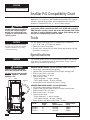
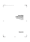
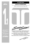
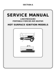
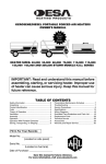
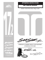
OPERATING INSTRUCTIONS
AND OWNERS MANUAL
w w w. s e a s t a r s t e e r i n g . c o m
172
IS O
.
9001
HYDRAULIC POWER ASSIST FOR SEASTAR
STEERING SYSTEMS
Including:
MANUFACTURED BY
TELEFLEX CANADA LIMITED
PARTNERSHIP
our way,way
y
it
o
d
u
o
y
Before please try it our
Notice to Boat Manufacturer
or Installer
Throughout this publication, Warnings and Cautions (accompanied by the
International Hazard Symbol
) are used to alert the manufacturer or
installer to special instructions concerning a particular service or
operation that may be hazardous if performed incorrectly or carelessly.
Observe Them Carefully!
These safety alerts alone, cannot eliminate the hazards that they
signal. Strict compliance to these special instructions when performing
the installation and maintenance plus common sense operation are major
accident prevention measures.
DANGER
Immediate hazards
which WILL result in
severe personal
injury or death.
WARNING
NOTICE
WARNING
Hazards or unsafe
practices which
COULD result in
severe personal
injury or death.
CAUTION
Hazards or unsafe
practices which
COULD result in
minor injury or
product or property
damage.
NOTICE
Information which is
important to proper
installation or
maintenance, but is
not hazard-related.
Cleaning fluids containing ammonia, acids or any other corrosive
ingredients MUST NOT be used for cleaning any part of this
Hydraulic Steering System. Failure to comply will cause serious
damage to the steering system, resulting in possible loss of
steering, causing property damage, personal injury and/or death.
Help protect your boating environment by ensuring that all used oil
is disposed of properly.
Don't compromise performance... use genuine
SeaStar parts only!
• SeaStar Helms
• SeaStar Hoses
• SeaStar Cylinders
• SeaStar Oil
Substituting non SeaStar parts in any part of the SeaStar hydraulic
steering system, may seriously compromise system performance.
Please ensure this manual is left on board the
boat for future reference.
Power Assist for SeaStar Systems
i
INTRODUCTION
Before proceeding with the installation, read these instructions
thoroughly. Teleflex cannot accept responsibility for installations
where instructions have not been followed, where substitute
parts have been used, or modifications have been made to
our products. Warranty may be void if products other than
Teleflex products are used with this system.
NOTICE
Due to a small amount of internal hydraulic slip, a "master spoke:
or "centered" steering wheel cannot be maintained with a Hydraulic
Steering System. For best results, use an equal distance spoke
steering wheel.
WARNING
DO NOT use a wire coil type trim switch with a hydraulic steering
system. Wire coil can wind up tight around the steering wheel
shaft and prevent further steering!
PRO Trim offers fingertip trim or jackplate control with a columnmounted switch, enabling you to keep both hands on the steering
wheel and concentrate on your driving. PRO Trim PT1000 controls
trim or jackplate only. PRO Trim Dual PT2000 controls both functions.
WARNING
SeaStar PRO Power Assist units are to be used with SeaStar PRO
Helms ONLY!
Index
NOTICE
This installation manual covers
the entire, SeaStar and SeaStar
PRO PA Series. Notes are made,
when required, to cover any
differences between the part
numbers.
Before Operating Your Boat ........................................................
Compatibility/Tools/Specifications..............................................
How The System Works .............................................................
Things You Need to Know ..........................................................
Before Starting .........................................................................
System Installation Overview......................................................
1
2
3
4
4
5
Specific Installation
Outboard Front Mount & HC5332 ............................................... 6
Side Mount & Splashwell Mount Cylinders .................................. 9
Inboard & Sterndrive ............................................................... 10
Autopilot Connection................................................................ 11
Electrical Installation ............................................................... 12
Power Purge Filling and Purging ................................................ 14
Manual Filling and Purging ....................................................... 15
Troubleshooting....................................................................... 21
Accessories ............................................................................ 23
Mounting Templates ................................................................ 25
Warranty ................................................................................. 29
The following Power Assist Units are covered in this installation
manual. PA1200-2, PA1225-2 and PA1315-2.
ii
SEASTAR Hydraulics
ii
BEFORE OPERATING
YOUR BOAT
WARNING
The SeaStar P/A unit has been
designed and tested for use with
Marine Hydraulic Steering ONLY.
It is not recommended for any
other use. Not complying with
this warning may result in
property damage and/or
personal injury or death.
Ensure that the following check list is carried out
1 With the P/A unit "OFF" (ignition off) perform a system pressure
test by turning the helm all the way to hard over and then forcing
the helm another one quarter to one half turn past the stop point.
Inspect the following areas for leaks.
- Inspect helm fittings
- Inspect P/A fittings
- Inspect cylinder fittings
Look for evidence of a leak. This test is to be done in BOTH
directions. Any leak that is noticed will need to be repaired
before operating the boat.
2 Confirm that extruded nylon tubing has NOT been
substituted for SeaStar/SeaStar PRO Hydraulic Steering hose.
3 Confirm that there is no interference between the steering
cylinder and the transom, splashwell or jackplate or any
combination of these parts by performing these simple steps:
• If installed on an outboard engine, with the engine fully titled,
turn steering from hard over to hard over and confirm that NO
interference occurs. If you are using a hydraulic jack plate this
also must be performed at the top and bottom position of the
jack plate. (If interference is present, it MUST be eliminated
with trim limiting switches and/or jack plate restrictors. Contact
Jack plate manufacturer for advice if required.)
• Confirm that the steering cylinder can be stroked fully in both
directions as well as full tilt and trim without stretching and/or
kinking the hydraulic hoses.
• Confirm that the hydraulic hose/tube are not subjected to chafing,
rubbing or stretching. Stretched, kinked or chafed hose/tube will
fail over a period of time leading to loss of steering control.
WARNING
Failure to comply with the above may result in loss of steering
control, leading to collision with obstacle(s), ejection from vessel
resulting in property damage and/or personal injury or death.
WARNING
Stretched, kinked or chafed hose will fail over a period of time.
CAUTION
If power to the unit is lost, the SeaStar Power Assist and SeaStar
Power Assist PRO will revert to manual steering, requiring substantially more effort to turn the wheel.
WARNING
When working in an area were fumes from fuel are present, allow
the fumes to disperse completely BEFORE doing any electrical
connection to the battery. Failure to do so may result in an
explosion and or fire.
Power Assist for SeaStar Systems
1
SEASTAR
HYDRAULIC POWER ASSIST
SeaStar P/A Compatibility Chart
The P/A and P/A PRO are designed for use in recreational marine
applications in conjunction with SeaStar and SeaStar PRO steering
systems. Optimal performance will be obtained when used with
SeaStar, or SeaStar PRO 1.4, 1.7 and 2.0 Helm pumps.
CAUTION
SeaStar nylon tube may ONLY be
used for the compensating line.
DO NOT use SeaStar Nylon tube
to plumb any other portion of the
steering system.
SeaStar P/A PRO is NOT to be used with SeaStar Hydraulic Steering,
performance will be compromised. ONLY use P/A PRO with a SeaStar
PRO Hydraulic steering system and ensure that SeaStar PRO (1500
psi) hose is used to plumb the entire system. (Nylon tubing may be
used for the compensating/return line ONLY.
Tools
NOTICE
Use ONLY Teleflex products with
the P/A unit as with ALL Teleflex
systems. Failure to do so may
void your warranty.
You will need the following tools to complete your installation.
• 1/2", 5/8", and 3/4" open end wrench.
• Electrical cut and crimp pliers.
• All other tools noted with your Helm Pump and Steering Cylinder
Installation Instructions.
Specifications
NOTICE
The SeaStar Power Assist will automatically recognize the voltage
level once it is connected to an on board power source (refer to
page 12 for electrical connections).
WARNING
ONLY use SeaStar PRO Power
Assist with a SeaStar PRO helm.
DO NOT exceed peak operating
pressure. 1000psi – Standard,
1500psi – Pro.
5/8"
3-3/4"
Figure 1.
SEASTAR POWER ASSIST 12/24V (PA1200-2 AND PA1225-2)
• 12/24 Volts (automatically recognized)
• 1000psi MAX system peak pressure (500psi working load)
• PEAK Current Draw = 60 amps
• MAX Current Draw = 40 amps
• Typical current draw:
– Single outboard ~ 3 amps, average
– Twin rudder inboard ~ 8 amps, average
• Purple ignition wire MAX current draw = 1 amp
8-3/16"
SEASTAR PRO POWER ASSIST, 12/24V (PA1315-2)
• 12/24 Volts (automatically recognized)
• 1500psi MAX System peak pressure (500psi working load)
• PEAK Current Draw = 60 amps
• MAX Current Draw = 40 amps
• Typical current draw:
– Single outboard ~ 3 amps, average
– Twin rudder inboard ~ 8 amps, average
• Purple ignition wire MAX current draw = 1 amp
5"
2
Part No.
Harness
Length
Voltage
(auto recognized)
Relief Pressure
Setting
PA1200-2
PA1225-2
PA1315-2
15'
25'
15'
12/24 Volt
12/24 Volt
12/24 Volt
1000psi
1000psi
1500psi
SEASTAR Hydraulics
HOW THE SYSTEM WORKS
SeaStar P/A (Power Assist) steering uses an electronically controlled
hydraulic pump to provide "Power" for your SeaStar Hydraulic
Steering system.
The SeaStar P/A system is comprised of two circuits: a hand operated
manual system, which is the control element, and a hydraulic power
pump, which is the working element.
The manual system consists of a helm pump with internal relief and
check valves, as well as a built in reservoir. Two steering lines and a
compensating line which provide a routing for fluid to transmit through
the system, and a steering cylinder which moves the steering device
on the boat from side to side.
The power system, is an electronically controlled hydraulic pump that
boosts the fluid being sent from the helm pump to the steering cylinder
(this will result in much easier effort at the wheel—even when under
heavy loads). A compensating line connects the P/A unit to the helm
pump, allowing the P/A unit to share fluid with the helm reservoir.
The SeaStar P/A is compatible with multiple steering stations, and
with the use of an autopilot. In the event of a P/A power loss or
failure the hydraulic system will automatically revert to a manual
hydraulic system.
Typical installations shown (please refer to you cylinder installation manual for proper hose
installation diagrams).
HELM
PUMP
H1
H2
C1
C2
HELM
PUMP
STEERING
LINES
STEERING
LINES
COMPENSATING
LINE
COMPENSATING
LINE
POWER
ASSIST
UNIT
SEASTAR OUTBOARD
CYLINDER
TILLER ARM
H1
H2
C1
C2
POWER
ASSIST
UNIT
SEASTAR INBOARD
CYLINDER
Figure 2.
Power Assist for SeaStar Systems
3
THINGS YOU NEED TO KNOW
WARNING
SeaStar/SeaStar PRO Steering hoses CANNOT be cut. Cutting
these hoses will render them useless. Failing to comply may result
in possible loss of steering causing property damage, personal
injury and/or death.
CAUTION
DO NOT use SeaStar Nylon tube with P/A unit, other than to plumb
the compensating line. Use of SeaStar or SeaStar PRO steering
hose is the ONLY hose recommended for use with the P/A unit.
CAUTION
Confirm that all components needed to complete the installation
are purchased, including: helm pump, steering cylinder, hoses,
fluid, fittings and pipe sealant such as Loctite PST, NEVER USE
TEFLON TAPE.
CAUTION
Take EXTREME care not to allow any foreign material or contamination
to enter the hydraulic system. Contamination is the main cause
for a hydraulic system to wear and or fail. Keep protective caps
on hose ends until ready to install onto the fitting.
NOTICE
The SeaStar and SeaStar PRO Power Assist pump will automatically
recognize the power source output (12/24Volt). If connecting SeaStar,
or SeaStar PRO Power Assist directly to the battery, the connection
MUST be fused in compliance with ABYC specifications.
BEFORE STARTING
Study this manual and the other manuals provided with your
SeaStar Steering system carefully, and thoroughly to familiarize
yourself with all of the components and their intended or required
mounting locations. Ensure there is adequate space available for
installation of all components, hydraulic lines, and easy access for
service. It is good practice to mount all components first, before
running hoses. This allows port to port connection with less
chance of an error. If you must run hoses first, a system of
marking the various lines must be used. ALL hose ends must be
closed with tape or similar material to prevent contamination.
Contamination is the most common cause of system failure.
Read ALL bold print text, notes and cautions. Reading them now
will help prevent unexpected surprises during the installation.
These instructions have been made as complete as
possible, but as brief as practical. If you have any questions,
contact your Distributor or Teleflex Canada.
4
SEASTAR Hydraulics
SYSTEM INSTALLATION
OVERVIEW
STEP 1
10° 10°
HELM
System Installation
• Install SeaStar Helm pump onto the dash using installation
instructions provided with your helm pump.
• Install Steering Cylinder into boat using the installation
instructions provided with your steering cylinder.
• The P/A unit will make a noise similar to that of an autopilot;
this should be taken into consideration if installing the P/A unit
into a center consul and/or in an area where noise is preferred
to be limited. Install the P/A unit in a vertical position (see
diagram) as close the steering cylinder as possible.
DO NOT mount the P/A unit in a horizontal position.
CYLINDER
WARNING The P/A motor may be HOT to the touch, DO NOT
mount P/A in an area where fabrics and/or any other flammable
material may come in contact with the P/A motor.
• Install steering hoses using diagrams noted on page 6 through
page 10, using your specific application.
P/A UNIT
The SeaStar PRO system must use SeaStar PRO
steering hoses.
WARNING
NOTICE
Due to the different cylinders options available
with SeaStar Steering, be sure that you choose the correct
installation diagram noted in this book.
NOTICE
Hoses MUST be at least 6’ in length from the power
assist to the helm pump, or, from the power assist to the cylinder(s).
STEP 2
Filling and Purging Procedure
• Refer to steps 1 through 5, located on page 15 of this manual.
CAUTION DO NOT run the P/A unit until the SeaStar
Steering System has been bled free of air. Failure to do so
may result in non-repairable damage to the P/A unit.
STEP 3
Electrical Installation
• Refer to page 12 of this manual for electrical connection.
STEP 4
Final Purge and System Check
• Turn ignition ON and continue with the filling and purging
instructions step 6 on page 18 of this manual
Power Assist for SeaStar Systems
5
SEASTAR POWER ASSIST
SYSTEM INSTALLATION
SeaStar Outboard Front Mount
Cylinders and I/O Cylinder
Outboard Front Mount
Cylinders:
HC5345 HC5347
HC5358 HC5348
HC6751 HC6750
HC6753 HC6752
HC6755 HC6754
Hose connection is as follows.
• Helm to P/A = S (helm) to H1 (P/A), P (helm) to H2 (P/A), lower R
port (helm) to R (P/A).
• P/A to cylinder = C2 (P/A) to starboard side (cylinder), C1 (P/A) to
port side (cylinder).
PORT
STARBOARD
I/O Cylinder:
HC5332
CAUTION
ALL hose connections MUST be
torqued to 15 ft-lb (20.34Nm).
R
H2
H1
P
S
R
NOTICE
Hoses MUST be at least 6' in
length from the power assist to
the helm pump, or, from the
power assist to the cylinder(s).
H1
HELM PUMP MODEL
& DISPLACEMENT
1.7 cu.in. per revolution
2.0 cu.in. per revolution
2.4 cu.in. per revolution
C1
5
4
3.5
WARNING
DO NOT run the wires or hoses
in areas where the may come
in contact with battery acid or
excessive heat, i.e. engine
exhaust, manifolds or any
other area that may damage
the wires or hoses.
C1
C2
Figure 3.
6
H2
R
WHEEL
TURNS
SEASTAR Hydraulics
C2
SEASTAR POWER ASSIST
SYSTEM INSTALLATION
NOTICE
Hoses MUST be at least 6' in
length from the power assist to
the helm pump, or, from the
power assist to the cylinder(s).
HELM PUMP MODEL
& DISPLACEMENT
WHEEL TURNS
CONFIG. A
'PARALLEL'
WHEEL TURNS
CONFIG. B
'SERIES'
10
8
6
5
4
3.5
1.7 cu.in. per revolution
2.0 cu.in. per revolution
2.4 cu.in. per revolution
PORT
STARBOARD
R
H2
H1
P
R
CAUTION
H1
ALL hose connections MUST be
torqued to 15 ft-lb (20.34Nm).
S
P
S
R
A
H2
ALIGNMENT
VALVE
H1
B
H2
R
C1
C2
R
C1
C2
WARNING
DO NOT run the wires or hoses
in areas where the may come
in contact with battery acid or
excessive heat, i.e. engine
exhaust, manifolds or any
other area that may damage
the wires or hoses.
C1
C2
Figure 4.
Power Assist for SeaStar Systems
7
SEASTAR POWER ASSIST
SYSTEM INSTALLATION
NOTICE
Hoses MUST be at least 6' in
length from the power assist to
the helm pump, or, from the
power assist to the cylinder(s).
HELM PUMP MODEL
& DISPLACEMENT
WHEEL TURNS
CONFIG. C
'PARALLEL'
WHEEL TURNS
CONFIG. D
'SERIES'
14.5
12.5
10.3
10
8
6
1.7 cu.in. per revolution
2.0 cu.in. per revolution
2.4 cu.in. per revolution
PORT
STARBOARD
R
H2
H1
P
P
S
S
R
R
CAUTION
ALL hose connections MUST be
torqued to 15 ft-lb (20.34Nm).
H1
C
ALIGNMENT
VALVE
R
C1
H1
H2
C1
C2
WARNING
DO NOT run the wires or hoses
in areas where the may come
in contact with battery acid or
excessive heat, i.e. engine
exhaust, manifolds or any
other area that may damage
the wires or hoses.
C1
C2
Figure 5.
8
D
SEASTAR Hydraulics
H2
R
C2
SEASTAR POWER ASSIST
SYSTEM INSTALLATION
SeaStar Outboard Side Mount and
Splashwell Mount Cylinders
Side Mount Cylinder:
HC5370
Splashwell Cylinder:
HC5380
NOTICE
Unbalanced cylinder will result
in unequal wheel turns.
Hose connection is as follows.
• Helm to P/A = S (helm) to H1 (P/A), P (helm) to H2 (P/A), lower R
port (helm) to R (P/A).
• P/A to cylinder = C1 (P/A) to starboard side (cylinder). C2 (P/A) to
port side (cylinder).
HELM PUMP MODEL
& DISPLACEMENT
1.7 cu.in. per revolution
2.0 cu.in. per revolution
2.4 cu.in. per revolution
WARNING
PORT
WHEEL TURNS
HC5370
WHEEL TURNS
HC5380
4.8/5.7
4.0/4.8
3.5/4.0
5.5/6.5
4.6/5.5
3.9/4.6
STARBOARD
DO NOT use SeaStar PRO systems
with HC5370 side mount and/or
HC5380 Splashwell mount
cylinders as SeaStar PRO systems
are not compatible with any
unbalanced cylinder.
R
NOTICE
Hoses MUST be at least 6' in
length from the power assist to
the helm pump, or, from the
power assist to the cylinder(s).
H2
H1
CAUTION
ALL hose connections MUST be
torqued to 15 ft-lb (20.34Nm).
WARNING
DO NOT run the wires or hoses
in areas where the may come
in contact with battery acid or
excessive heat, i.e. engine
exhaust, manifolds or any
other area that may damage
the wires or hoses.
C1
H1
H2
C1
C2
C2
Figure 6.
Power Assist for SeaStar Systems
9
SEASTAR POWER ASSIST
SYSTEM INSTALLATION
SeaStar Inboard and Sterndrive
Cylinders ALL
All Inboard & Sterndrive
Except: HC5332
Hose connection is as follows.
• Helm pump to P/A = S (helm) to H1 (P/A), P (helm) to H2 (P/A),
lower R port (helm) to R (P/A).
• P/A to cylinder = C1 (P/A) to starboard side (cylinder), C2 (P/A)
to port side (cylinder).
NOTICE
Hoses MUST be at least 6' in
length from the power assist to
the helm pump, or, from the
power assist to the cylinder(s).
HELM PUMP MODEL
& DISPLACEMENT
1.7 cu.in. per revolution
2.0 cu.in. per revolution
2.4 cu.in. per revolution
CAUTION
HC5312-2
HC5313
4.2
3.6
3
5
4
3.5
PORT
WHEEL TURNS
HC5314 HC5318
6
5
4.2
HC5319
6
5
4.2
8
6.8
5.7
STARBOARD
ALL hose connections MUST be
torqued to 15 ft-lb (20.34Nm).
WARNING
DO NOT run the wires or hoses
in areas where the may come
in contact with battery acid or
excessive heat, i.e. engine
exhaust, manifolds or any
other area that may damage
the wires or hoses.
R
H2
C1
H1
C2
Figure 7.
10
SEASTAR Hydraulics
H1
H2
C1
C2
SEASTAR POWER ASSIST
SYSTEM INSTALLATION
Autopilot Connection Detail
NOTICE
Installation and operation can be
simplified with the purchase of a
SeaStar AutoPilot Pump. Contact
Teleflex Marine for details.
Hose connection is as follows.
• Autopilot pump MUST be connected to the steering lines AFTER
the P/A (see diagram below). The return R line MUST be tee'd
into the system in front of the P/A unit (see diagram below).
• Refer to page 6 through page 10 for you cylinder application.
• When bleeding, ensure that the autopilot Reservoir line is bled
free of air at the same time the Power Assist Reservoir line is
bled free of air. Autopilot pump must be run in both directions
during the bleeding procedure, refer to page 18 for details.
NOTICE
PORT
STARBOARD
Hoses MUST be at least 6' in
length from the power assist to
the helm pump, or, from the
power assist to the cylinder(s).
WARNING
DO NOT run the wires or hoses
in areas where the may come
in contact with battery acid or
excessive heat, i.e. engine
exhaust, manifolds or any
other area that may damage
the wires or hoses.
P
S
R
H1
H2
R
C1
P
R
C2
S
AUTOPILOT
PUMP
Figure 8.
Power Assist for SeaStar Systems
11
SEASTAR POWER ASSIST
SYSTEM INSTALLATION
Electrical Installation
WARNING
ALWAYS use ABYC compliant components in electrical installations
of the Power Assist and any other electrical device being installed
on board the vessel. Failure to do so may result in a fire and/or
explosion leading to property damage, personal injury and/or death.
WARNING
The Power Assist wiring may be cut
to length as per your installation.
If connecting directly to a battery there MUST be an overcurrent
protection as per ABYC E11.12 OVERCURRENT PROTECTION.
Failure to do so may result in a fire and/or explosion leading to
property damage, personal injury and/or death.
• Refer to wiring diagram on page 13 of this manual.
• Connect Red wire (+ positive) to the positive (+) supply
• Connect Black wire (– negative) to the negative (–) supply
• Connect purple wire (Power) to the ignition of the boat. Use of a
two-position ON/OFF switch is recommended, use a fuse protected
switch ONLY. Use of this switch will allow the helmsman to turn
the Power Assist OFF in the case of power supply being limited.
NOTICE
Always use appropriate wiring terminals as per ABYC requirements.
NOTICE
WARNING
NOTICE
12
Overcurrent protection MUST be used to connect the SeaStar Power
Assist in a distribution panel or to a battery. The overcurrent may be:
• An ABYC compliant, 50AMP rated circuit breaker, or
• An in-line MAXI fuse, Teleflex part # HA1206
• If the location of the SeaStar Power Assist unit is within 72" of
the battery, the main over-current protection (fuses) within the
Power Assist unit itself will meet ABYC requirements.
If applicable, complete the wiring from the distribution panel to the
boat battery in accordance to ABYC E-11.10 Load Calculation and
E-11.16 System wiring.
SEASTAR Hydraulics
SEASTAR POWER ASSIST
SYSTEM INSTALLATION
Wiring Diagram
NOTICE
For multiple engine applications
it is advisable to install a Dual
Ignition Control Kit (part#
HA1201). This kit will enable
the Power Assist to work in the
event an engine(s) may not be
running.
DISTRIBUTION
PANEL
– BLACK
+ RED
BRANCH
CIRCUITS
PURPLE
WARNING
DO NOT run the wires or hoses
in areas where the may come
in contact with battery acid or
excessive heat, i.e. engine
exhaust, manifolds or any
other area that may damage
the wires or hoses.
MAIN
OVERCURRENT
PROTECTION
BATTERY
SWITCH
+
2 x 40 amp ATO/ATC fuses are
located inside the rear panel of
the SeaStar Power Assist Pump.
NOTICE
Power Assist for SeaStar Systems
-
BATTERY
12 OR 24 VOLT
NOTICE
NOTICE
-
P/A UNIT
ON/OFF SWITCH
(OPTIONAL SEE
NOTICE BELOW)
If the location of the SeaStar
Power Assist unit is within 72" of
the battery, the main overcurrent
protection (fuses) within the unit
itself will meet ABYC requirements.
+
OVERCURRENT
PROTECTION
IGNITION
MAIN
OVERCURRENT
PROTECTION
TO FUSED
POWER SUPPLY
12 OR 24 VOLT
+
-
BATTERY
12 OR 24 VOLT
OPTIONAL
Figure 9.
It is recommended that a two position switch is purchased to allow
the P/A unit to be turned off to help conserve battery power in a
situation where battery power is limited. In order to prevent accidental
P/A shut down, Teleflex recommends the use of a 12-Volt, 15 amp,
ON/OFF, rocker style or push button style switch. ON/OFF switches
are not available from Teleflex.
13
POWER PURGE FILLING AND
PURGING THE SYSTEM
NOTICE
If system is plumbed as shown in Config. B (page 7), C (page 8) or D
(page 8), please contact Teleflex Marine for specific bleeding details.
NOTICE
BEFORE bleeding the main steering system (helm, hoses and
cylinders), the RETURN line will need to be purged.
Step 1
CAUTION
Refer to your Power Purge
installation manual for important
Warnings and Notices while
using the Power Purge Units.
NOTICE
NOTICE
14
DO NOT OPEN MANUAL BLEED VALVE WHEN USING A POWER PURGER
• Turn ON the Power Purge unit and continue to run until NO air is
visible leaving the P/A unit.
• Turn OFF Power Purge unit.
• Close reservoir bleed fitting and continue on with the following steps.
• Ensure the reservoir bleed fitting is closed then remove the hose
from the reservoir bleed fitting and connect to the steering cylinder
bleeder fittings. Ensure the quick connect is locked onto the fitting.
• Open ALL Cylinder bleed fittings 1-1/2 turn.
Step 2
Step 3
Removing Air from Return Line
• Install the helm adapter into the helm pump and attach the helm
hose from the power purge unit.
• Connect one of the fluid return hoses (cylinder lines) from the
Power Purge unit to the Reservoir bleed fitting on the P/A unit.
(see figure 10 on page 16 for bleed fitting location).
• Open reservoir bleed fitting 1 turn.
DO NOT OPEN MANUAL BLEED VALVE WHEN USING POWER
PURGE UNITS.
• Turn Power Purge unit ON.
• Oil should flow into and out of the helm pump. Wait twenty
seconds for the helm to fill with oil.
• Turn the steering wheel clockwise until the cylinder rod is fully
extended (you may have to manually push the cylinder rod).
SLOWLY continue to turn the wheel to hold the cylinder in this
position for approximately 30 seconds. Ensure there are NO air
bubbles escaping through the cylinder hoses.
• Turn the steering wheel counter-clockwise until the cylinder rod is
fully extended (you may have to manually push the cylinder rod).
SLOWLY continue to turn the wheel to hold the cylinder in this
position for approximately 30 seconds. Ensure there are NO air
bubbles escaping through the cylinder hoses.
• Turn OFF Power Purge unit
• Tighten ALL bleed fittings on the steering cylinder(s)
• Repeat above steps with the Power Assist unit ON.
Continue on with Oil Level and System Check on page 20.
SEASTAR Hydraulics
MANUAL FILLING AND
PURGING THE SYSTEM
These instructions show how to fill and purge a SeaStar Steering
System with the P/A unit installed. The same steps apply to ALL
cylinders with the exception of which bleed fitting to open and close
and the direction the cylinder rod moves. These variations are
shown in inset diagrams at each step. For multiple steering stations,
start with the lowest station while going through Steps 1 – 7,
repeat at each higher station until complete.
Read First
CAUTION
Hydraulic Oil Requirements
DO NOT turn ON P/A unit until manual portion is completed.
This procedure requires two people. One person may not be able
to remove all the air from the system, which will result in spongy,
unresponsive steering.
During the entire filling procedure, oil MUST be visible in the filler
tube. DO NOT allow oil level to disappear into the helm pump, as
this may introduce air into the system and increase your filling time.
2 bottles (2 quarts or liters) for single station and single cylinder
systems. One additional bottle for each cylinder, helm, and or
autopilot added to the system.
NOTICE
Oil can be re-used if filtered through a fine mesh screen such as
that used for gasoline. If unable to filter oil, an additional bottle of
fluid is required.
NOTICE
"Bleeder" refers to cylinder or P/A unit fitted with bleed fittings.
Bleed fittings can be opened by unscrewing bleed nipple nut two
turns.
NOTICE
Protect your boating environment by ensuring that all used oil is
disposed of properly.
Single Station One Cylinder
NOTICE
BEFORE bleeding the main steering system (helm, hoses and
cylinders), the RETURN line will need to be purged.
Removing Air From Return Line
• Install the fill tube and fluid fill bottle into the helm pump.
Step 1
NOTICE
Power Assist for SeaStar Systems
Filling the helm full of fluid prior to connecting the filler tube and oil
bottle will decrease purge time.
• Open the manual bleed valve (see Figure 10) and reservoir bleed
fitting (see Figure 10) on the power assist unit. The manual bleed
valve should be opened two full turns.
15
SEASTAR POWER ASSIST
FILLING AND PURGING
• Fill helm with fluid, then, turn steering wheel to the starboard side
until a steady stream of "air-free" oil comes out of the reservoir
bleed fitting on the Power Assist Unit.
• Close reservoir bleed fitting.
• Continue to turn the wheel to starboard another 15 turns after closing
the reservoir bleed fitting and prior to closing the manual bleed valve.
• Close manual bleed valve and continue with Steps 2 – 5.
PUSH PIN
FILLER PLUG
(REMOVED)
RESERVOIR BLEED FITTING
FILLER KIT
HELM FILL PORT
MANUAL BLEED VALVE
DO NOT LET
OIL LEVEL
FALL BELOW
THIS POINT
R
H2
H1
Figure 10.
• Turn the steering wheel clockwise until the cylinder rod is fully
extended on the right side of the cylinder.
• Open bleed fitting as per your installation.
Step 2
TURN
CLOCKWISE
OPEN RIGHT SIDE
BLEEDER
Outboard Front Mount & HC5332 Cylinder
16
TURN
CLOCKWISE
OPEN LEFT SIDE
BLEEDER
Side Mount / Splashwell Mount Cylinder
TURN
CLOCKWISE
OPEN LEFT SIDE
BLEEDER
All Balanced Cylinder. Inboard & Sterndrive Cylinders
SEASTAR Hydraulics
SEASTAR POWER ASSIST
FILLING AND PURGING
Step 3
• Holding the cylinder body (Front Mount cylinder) or rod (Side
Mount cylinder) to prevent the body/rod from moving, turn the
steering wheel counter-clockwise until a steady stream of air free
oil comes out of the bleeder. (Drain approx. 1/2 bottle of oil or as
required).
Do not use anything other than your hands to restrain the
cylinder body/rod.
• While continuing to turn the wheel close the bleed fitting for your
application and let go of the cylinder body/rod.
TURN COUNTERCLOCKWISE
CLOSE RIGHT
SIDE BLEEDER
TURN COUNTERCLOCKWISE
TURN COUNTERCLOCKWISE
CLOSE LEFT SIDE
BLEEDER
CLOSE LEFT SIDE
BLEEDER
Outboard Front Mount & HC5332 Cylinder
Side Mount / Splashwell Mount Cylinder
Step 4
• Continue turning the steering wheel counter-clockwise until the cylinder
rod is fully extended to the left. (Steering wheel will come to a stop).
• Open bleed fitting as per your installation.
TURN COUNTERCLOCKWISE
TURN COUNTERCLOCKWISE
Power Assist for SeaStar Systems
TURN COUNTERCLOCKWISE
OPEN
RIGHT
SIDE
BLEEDER
OPEN LEFT
SIDE BLEEDER
Outboard Front Mount & HC5332 Cylinder
All Balanced Cylinder. Inboard & Sterndrive Cylinders
Side Mount / Splashwell Mount Cylinder
OPEN
RIGHT
SIDE
BLEEDER
All Balanced Cylinder. Inboard & Sterndrive Cylinders
17
SEASTAR POWER ASSIST
FILLING AND PURGING
• Holding the cylinder body (Front Mount cylinder) or rod (Side Mount
cylinder) to prevent the body/rod from moving, turn the steering
wheel clockwise until a steady stream of air free oil comes out of
the bleeder.
• While continuing to turn the wheel close the bleed fitting for your
application and let go of the cylinder body/rod.
Step 5
CAUTION
TURN CLOCKWISE
CLOSE LEFT SIDE
BLEEDER
Prior to operating system, perform Oil Level System Check, refer
to page 20.
TURN CLOCKWISE
TURN CLOCKWISE
CLOSE
RIGHT SIDE
BLEEDER
CLOSE
RIGHT SIDE
BLEEDER
All Balanced Cylinder. Inboard & Sterndrive Cylinders
Outboard Front Mount & HC5332 Cylinder
Side Mount / Splashwell Mount Cylinder
Step 6
• Complete electrical connections as outlined in your Installation
Owner’s Manual.
• Repeat Steps 2 – 5 of purging instructions with the P/A unit "ON"
NOTICE
18
Be sure to remove ALL air from the autopilot reservoir line.
If the system has an autopilot installed, ensure that the autopilot
pump is run for at least 10 seconds in both directions during Step 3
and Step 5.
SEASTAR Hydraulics
SEASTAR POWER ASSIST
FILLING AND PURGING
Twin Station Single Cylinder
Perform Steps 1 – 6 at station
no. 1. Then repeat Steps 2 – 5
at station no. 2.
STATION NO.2
STATION NO.1
Note: Refer to Oil Level &
System Check on page 20.
P/A UNIT
CYLINDER
Single Station Twin Cylinder
When performing Steps 2 – 5,
perform instructions in each
step first on cylinder no. 1 and
then on cylinder no. 2, before
proceeding to the next step. ie:
Perform instructions referring
to right side of cylinder first on
cylinder no. 1 and then on
cylinder no. 2.
P/A UNIT
CYLINDER NO.2
CYLINDER NO.1
Note: Refer to Oil Level &
System Check on page 20.
Twin Station Twin Cylinder
Follow same procedure as
instructed for single station-twin
cylinders, beginning at station
no. 1, and repeat entire
procedure at station no. 2.
STATION NO.2
STATION NO.1
P/A UNIT
Note: Refer to Oil Level &
System Check on page 20.
CYLINDER NO.2
Power Assist for SeaStar Systems
CYLINDER NO.1
19
SEASTAR POWER ASSIST
FILLING AND PURGING
Oil Level and System Check
At this time the steering system must be checked for proper
connections hose and fittings, possible leaks, and air removal.
Please complete the following steps with the P/A Unit OFF.
• Turn steering wheel to hard over, then force the wheel another one
quarter to one half turn past the stop point. Check the following
areas for evidence of a leak.
- Helm fitting connections.
- P/A fitting connections
- Cylinder fitting connections
• Repeat above steps to the other steering direction.
• Any sign of a leak MUST be repaired prior to operating the boat.
• While turning steering wheel observe fluid level in the helm pump.
If fluid level drops and rises as the wheel is being turned there is
still air in the system. Complete bleeding instructions again until
no obvious fluid level change is noticed.
NOTICE
Helms mounted with the wheel shaft completely horizontal must be
filled to the bottom of the filler hole at all times. Do NOT allow the
fluid level to drop more than one-quarter inch below the filler hole.
NOTICE
Helms mounted on a 20 degree angle or with the wheel shaft vertical
MUST have the fluid level within 1/2" of the filler hole, refer to the
diagram below.
VERTICAL
1/2"
(12.5mm)
20∞
Figure 11.
20
SEASTAR Hydraulics
TROUBLESHOOTING GUIDE
FAULT
CAUSE
SOLUTION
1. P/A unit does not
Blown Fuse/Breaker
Replace 'external' fuse if blown first.
Replace 'internal' fuse if blown second.
Or, reset breaker.
NOTICE
2 x 40 amp ATO/ATC fuses are
located inside the rear panel of the SeaStar
Power Assist Pump.
WARNING If it is necessary to replace the
fuse(s) in the Power Assist Unit, ensure
the Power Assist Unit is turned OFF.
Refer to wiring diagram and location of
fuse on on page 13.
turn on.
Wrong electrical connections
2. Turns the wrong way
Lines reversed
Review the plumbing diagrams for your system
noted on page 6 through page 10, confirm
that your hoses are hooked up correctly.
3. Wheel is bumpy
Air in system
Re-Bleed. Concentrate on remaining air in
the P/A unit.
Autopilot has not been bled as per instructions.
4. Helm locks up in both
Hoses installed in the wrong
ports.
Review the plumbing diagrams for your system
noted on page 6 through page 10, confirm
that your hoses are hooked up correctly.
Check ALL lines for sign of a collapsed or
kinked line.
directions
Kinked or collapsed line
5. Helm only turns in one
Port or Starboard line is
connected to the reservoir R
port on the P/A unit.
Review the plumbing diagrams for your system
noted on page 6 through page 10, confirm
that your hoses are hooked up correctly.
6. Steering is very hard (stiff)
P/A unit is not turned on.
Partially kinked or collapsed
line.
H1, H2 or R port screen
filters are plugged with
contamination.
See fault #1
Check ALL lines for a sign of a collapsed
or kinked line
Remove H1, H2 and R hose and fittings.
Clean screens located in the adapter fittings.
7. No Power Assist, Lights are
Note sequence of blinking
lights
See page 22 for details
Helm is super charging
Super charging is a normal occurrence with
ALL PRO systems, while running at higher
loads and/or hitting the hard over point.
This should not be taken as a fault in the
system.
direction and free wheels
in the other
blinking.
8. After hitting hard over and/or
running at high loads with the
SeaStar PRO Power Assist,
the effort at the wheel
increasing dramatically.
Power Assist for SeaStar Systems
21
FAULT
CAUSE
SOLUTION
9. The power assist unit is
Motor operating
This is a normal occurrence with the Power
Assist unit; mount the P/A in an area
where it can not easily be handled and
away from flammable materials.
Hitting hard-over causing hose
expansion.
Power assist is pressurizing
system.
This is a normal occurrence when using
the power assist system.
This is a normal occurrence when using a
power assist.
really hot to the touch.
10. Lock to lock wheel turns
are different with the power
assist “off” than with the
power assist “on”.
WARNING
NOTICE
Whenever a solution calls for the removal from vessel and/or
dismantling of steering system components, such work must
ONLY be carried out by a qualified marine hydraulic mechanic.
Teleflex offers this information as a guide ONLY and is not
responsible for any consequences resulting from incorrect
repairs. When in doubt, contact your parts distributor or Teleflex
for assistance.
The Green and Red lights are used to show the status of the SeaStar
Power Assist Units. Below is a quick list as to what the lights refer
to. Any fault within the Power Assist Unit will be acknowledged via
the RED light flashing in the sequences noted below.
• GREEN. Steady (no flash)
Normal operation.
• RED. Two flashes, long pause
Standby mode, lack of calibration.
SOLUTION: Contact Teleflex Marine.
• RED. Three flashes, long pause
Calibration mode.
SOLUTION: Turn OFF ignition, after one minute, turn ignition ON.
If problem persists, contact Teleflex Marine
• RED. Four flashes, long pause
Overvoltage mode.
SOLUTION: check ignition and battery voltage. MUST be less
than 32Volts, correct as required.
22
SEASTAR Hydraulics
ACCESSORIES
SeaStar P/A Dual Ignition
Control Kit
Part# HA1201
The Dual Ignition Control Kit is designed to connect the P/A unit's
ignition wire to two engines allowing one engine to be turned off
and retain power assist control.
NOTICE
ENGINE #1
P/A UNIT
For each and every engine fitted
after two (triples, quads... etc.),
you will require one more
HA1201 kit per engine being
added.
ENGINE #3
ENGINE #2
Figure 12.
SeaStar Power Purge JR.
Part# HA5445-2
SeaStar®/BayStar™ Power Purge Jr. is the quickest way to bleed a
SeaStar®/ BayStar™ system in the field and assure a rock-solid
steering feel every time!
Figure 13.
Advantages:
Power Assist for SeaStar Systems
• Steering feel is solid every time
• Complete Fill & Purge in 10
minutes or less
• Fast and efficient
• Easy to operate
• Screens contaminants from oil
• Quick connect fittings
• Convenient portable size
• Convenient electrical hook-up
utilizing 12 volt boat battery
• Optional Dual Cylinder Purging
Kit HA5461 available
Optional
50’ Hose Extension
•
Kit HA5462, for longer runs
23
24
SEASTAR Hydraulics
Floor Mounting
Template
5"
(127 mm)
NOTICE
If printing, or photocopying from
this page. Using a ruler, confirm
that the measurements shown
on the print out are as stated on
this page BEFORE drilling.
5-.42"
(138 mm)
TOP OF POWER
ASSIST UNIT
1-3/8"
(35 mm)
Power Assist for SeaStar Systems
2-1/2"
(64 mm)
2 x .22"
25
26
SEASTAR Hydraulics
Wall Mounting
Template
3.7"
(94 mm)
4 x .22"
NOTICE
If printing, or photocopying from
this page. Using a ruler, confirm
that the measurements shown
on the print out are as stated on
this page BEFORE drilling.
8.19"
(208 mm)
FRONT OF POWER
ASSIST UNIT
5.0"
(127 mm)
Power Assist for SeaStar Systems
27
28
SEASTAR Hydraulics
Statement of Limited Warranty
We warrant to the original retail purchaser that Teleflex Canada
Limited Partnership products have been manufactured free from
defects in materials and workmanship. This warranty is effective for
two years from date of purchase, excepting that where Teleflex
Canada Limited Partnership products are used commercially or in
any rental or income producing activity, then this warranty is limited
to one year from the date of purchase.
We will provide replacement product without charge, for any Teleflex
Canada Limited Partnership product meeting this warranty, which is
returned (freight prepaid) within the warranty period to the dealer
from whom such product were purchased, or to us at the appropriate
address. In such a case Teleflex Canada Limited Partnership
products found to be defective and covered by this warranty, will be
replaced at Teleflex’s option, and returned to the customer.
The above quoted statement is an extract from the complete
Teleflex Canada Limited Partnership products warranty statement.
A complete warranty policy is available in our Teleflex Canada
Limited Partnership products catalogue.
Return Goods Procedure
Prior to returning product to Teleflex Canada Limited Partnership
under warranty, please obtain a Return Goods Authorization number
(claim number).
Be sure to label the goods with:
a) the name and address of the sender, and
b) the return goods authorization number (claim number)
Please address the returned goods as follows:
From U.S.A.
RGA # ?
Teleflex Canada
c/o UPS-SCS Warehouse
1927 Boblett Street
Blaine, WA 98230
Power Assist for SeaStar Systems
From Canada
RGA # ?
Teleflex Canada
3831 No.6 Road
Richmond, B.C.
Canada V6V 1P6
29
30
SEASTAR Hydraulics
MARINE
TELEFLEX CANADA
3831 NO.6 ROAD
RICHMOND, B.C.
CANADA V6V 1P6
FAX 604-270-7172
www.seastarsteering.com
ISO 10592
© 2007 TELEFLEX CANADA LIMITED PARTNERSHIP
PRINTED IN CANADA
FORM NO. 298403 1300-10/08 Rev. A