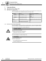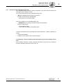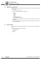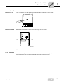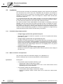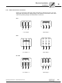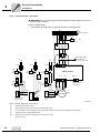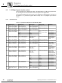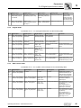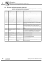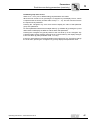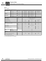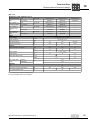
1
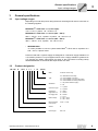
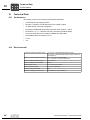
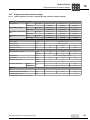
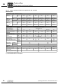
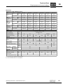
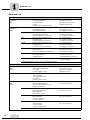
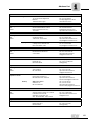
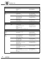
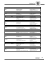
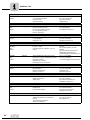
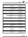
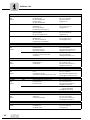
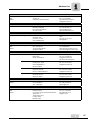
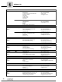
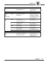
Drive Technology \ Drive Automation \ System Integration \ Services
Operating Instructions
MOVITRAC® LTE-B
Edition 09/2010
16923626 / EN
SEW-EURODRIVE—Driving the world
1 Important Notes................................................................................................. 4
1.1 Structure of the safety notes ..................................................................... 4
1.2 Application environment............................................................................ 6
1.3 Waste disposal.......................................................................................... 6
2 Safety Notes ...................................................................................................... 7
2.1 Installation and startup .............................................................................. 7
2.2 Operation and servicing ............................................................................ 8
3 General specifications ...................................................................................... 9
3.1 Input voltage ranges ................................................................................. 9
3.2 Product designation .................................................................................. 9
3.3 Overload capability ................................................................................. 10
3.4 Protection features .................................................................................. 10
4 Mechanical Installation ................................................................................... 11
4.1 Dimensions ............................................................................................. 11
4.2 IP20 housing: mounting and dimensions of switch cabinet..................... 16
5 Electrical Installation ...................................................................................... 18
5.1 Prior to installation .................................................................................. 18
5.2 Installation ............................................................................................... 20
5.3 Signal terminals overview ....................................................................... 24
5.4 RJ45 Communication Socket.................................................................. 25
5.5 UL-compliant installation ......................................................................... 26
5.6 Electromagnetic compatibility.................................................................. 27
6 Startup.............................................................................................................. 29
6.1 User interface.......................................................................................... 29
6.2 Easy startup ............................................................................................ 30
7 Operation ......................................................................................................... 35
7.1 Drive status ............................................................................................. 35
8 Service and fault codes .................................................................................. 36
8.1 Troubleshooting ...................................................................................... 36
8.2 Fault history ............................................................................................ 36
8.3 Fault codes ............................................................................................. 37
8.4 SEW electronics service ......................................................................... 38
9 Parameters....................................................................................................... 39
9.1 Standard parameters .............................................................................. 39
9.2 Extended parameters.............................................................................. 40
9.3 P-15 Digital inputs function select ........................................................... 44
9.4 Real-time monitoring parameters (read-only) ......................................... 46
10 Technical Data ................................................................................................. 48
10.1 Conformance .......................................................................................... 48
10.2 Environmental ......................................................................................... 48
10.3 Output power and current ratings............................................................ 49
11 Index ................................................................................................................. 58
Operating Instructions – MOVITRAC® LTE-B
3
Important Notes
Structure of the safety notes
1
1
Important Notes
1.1
Structure of the safety notes
1.1.1
Meaning of the signal words
The following table shows the grading and meaning of the signal words for safety notes,
notes on potential risks of damage to property, and other notes.
Operating Instructions
Signal Word
1.1.2
Meaning
Consequences if disregarded
DANGER
Imminent danger
Severe or fatal
injuries
WARNING
Possible dangerous situation
Severe or fatal
injuries
CAUTION
Possible dangerous situation
Minor injuries
NOTICE
Possible damage to property
Damage to the drive system or its environment
INFORMATION
Useful information or tip: Simplifies
the handling of the drive system.
Structure of the section safety notes
The section safety notes do not apply to a specific action, but to several actions pertaining to one subject. The pictograms used indicate either a general or a specific hazard.
This is the formal structure of a section safety note:
SIGNAL WORD
Nature and source of hazard.
Possible consequence(s) if disregarded.
•
Measure(s) to prevent the hazard.
This is an example for a section safety note:
WARNING
Falling of suspended loads.
Severe or fatal injuries.
4
•
Do not stand under the suspended load.
•
Secure the danger zone.
Operating Instructions – MOVITRAC® LTE-B
Important Notes
Structure of the safety notes
1.1.3
1
Structure of the embedded safety notes
The embedded safety notes are directly integrated in the instructions just before the
description of the dangerous action.
This is the formal structure of an embedded safety note:
•
SIGNAL WORD Nature and source of hazard.
Possible consequence(s) if disregarded.
– Measure(s) to prevent the hazard.
This is an example for an embedded safety note:
•
DANGER Risk of crushing if the drive restarts unintentionally.
Severe or fatal injuries.
– De-energize the drive.
– Secure the drive against unintended restart.
Unless the information in the operating instructions is adhered to, it will be impossible to
ensure:
•
Trouble-free operation
•
Fulfillment of any rights to claim under guarantee
Consequently, read the operating instructions before you start working with the
unit!
The operating instructions contain important information about servicing. Therefore,
keep the operating instructions close to the unit.
Operating Instructions – MOVITRAC® LTE-B
5
Important Notes
Application environment
1
1.2
Application environment
The following applications are forbidden unless measures are expressly taken to make
them possible:
•
Use in explosion-proof areas.
•
Use in environments with harmful substances:
–
–
–
–
–
–
–
1.3
Oils
Acids
Gases
Vapors
Dust
Radiated interference
Other harmful environments
•
Use subject to mechanical vibration and shock loads in excess of the requirements
in EN 50178.
•
If the inverter performs safety functions which have to guarantee the protection of
machinery and people.
Waste disposal
Please follow the current instructions: dispose in accordance with the regulations in
force:
6
•
Electronics scrap (printed-circuit boards)
•
Plastic (housing)
•
Sheet metal
•
Copper
Operating Instructions – MOVITRAC® LTE-B
Safety Notes
Installation and startup
2
2
Safety Notes
MOVITRAC® LTE-B drive inverters may not perform safety functions without higherlevel safety systems.
Do not use MOVITRAC® LTE-B drive inverters for any safety functions in conjunction
with hoist applications.
2.1
Installation and startup
•
Never install or start up damaged products. Please submit a complaint to the
transport company immediately in the event of damage.
•
Installation, startup and service work on the unit only by trained personnel.
The personnel must be trained in the relevant aspects of accident prevention
and must comply with the regulations in force (e.g. EN 60204, VBG 4,
DIN-VDE 0100/0113/0160).
•
Follow the specific instructions during installation and startup of the motor and
the brake!
•
Make sure that preventive measures and protection devices correspond to the
applicable regulations (e.g. EN 60204 or EN 50178).
Grounding the unit is a necessary protective measure.
Overcurrent protection devices are a necessary protective measure.
•
The unit meets all requirements for reliable isolation of power and electronics
connections in accordance with UL508. All connected circuits must also satisfy
the requirements for reliable isolation in order to guarantee reliable isolation.
•
Take suitable measures to ensure that the connected motor does not start up
automatically when the inverter is switched on. To do this, you can connect binary
inputs DI01 through DI03 to GND.
•
Integral solid state short circuit protection does not provide branch circuit protection. Branch circuit protection must be provided in accordance with the National
Electrical Code and any additional local codes.
Operating Instructions – MOVITRAC® LTE-B
7
Safety Notes
Operation and servicing
2
2.2
Operation and servicing
WARNING
Danger of electrical shock. High voltages are present in the terminals and within the
drive for up to 10 minutes after the electrical supply has been disconnected.
Severe or fatal injuries.
8
•
Disconnect and isolate the MOVITRAC® LTE-B from the electrical supply at least
10 minutes before commencing any work on it.
•
Dangerous voltages are present in the output terminals and the cables and motor
terminals connected to them when the unit is switched on. Dangerous voltages may
also be present when the unit is inhibited and the motor at a standstill.
•
The unit is not necessarily deenergized when the LEDs and the 7-segment
display are off.
•
Safety functions inside the unit or a mechanical blockage may cause the motor
to stop. The removal of the source of the malfunction or a reset can result in an
automatic restart of the drive. If, for safety reasons, this is not permissible for the
driven machine, disconnect the unit from the supply system before correcting the
fault.
Operating Instructions – MOVITRAC® LTE-B
General specifications
Input voltage ranges
3
General specifications
3.1
Input voltage ranges
3
Depending on model and power rating the drives are designed for direct connection to
the following supplies:
MOVITRAC® LTE-B sizes 1, 2 (115 V input):
115 V ± 10 %, 1-phase, 50 – 60 Hz ± 5 %
MOVITRAC® LTE-B sizes 1, 2 and 3s (200 – 240 V):
200 V – 240 V ± 10 %, 1-phase* / 3-phase, 50 – 60 Hz ± 5 %
MOVITRAC® LTE-B sizes 1, 2 and 3s (380 – 480 V):
380 V – 480 V ± 10 %, 3-phase, 50 – 60 Hz ± 5 %
•
INFORMATION
*It is also possible to connect 1-phase MOVITRAC® LTE-B units to 2-phases of a
200 – 240 V, 3-phase mains.
Products used with a 3-phase supply are designed for a maximum supply imbalance of
3 % between phases. For input supplies which have a supply imbalance greater than
3 % (typically the Indian subcontinent and parts of the Asia Pacific including China)
SEW-EURODRIVE recommends that input chokes are used.
3.2
Product designation
MC LTE
B
0015
2 0
1
1
00
Operating Instructions – MOVITRAC® LTE-B
(60 Hz)
60Hz
American version only
Type
00 = Standard IP20 housing
10 = IP55 / NEMA 12 housing
20 = IP55 / NEMA 12 housing with switch
40 = IP66 / NEMA 4X housing with switch
Quadrants
1 = 1Q (without brake chopper)
4 = 4Q
Connection type
1 = 1-phase
3 = 3-phase
Interference
suppression on
the supply side
0 = class 0
A = class A
B = class B
Mains voltage
1 = 115 V
2 = 200 – 240 V
5 = 380 – 480 V
Recommended
motor power
0015 = 1.5 kW
Version
B
Product type
MC LTE
9
General specifications
Overload capability
3
3.3
Overload capability
All MOVITRAC® LTE-B units have a possible overload of:
•
150 % for 60 seconds
•
175 % for 2 seconds
The overload is reduced to 150 % for 7.5 seconds if the output frequency is below
10 Hz.
For motor overload adjustment see parameter P-08 in chapter "Standard parameters"
(page 39).
3.4
Protection features
•
Output short-circuit, phase-to-phase, phase-to-ground
•
Output over-current
•
Overload protection
– Drive delivers 150 % of rated motor current for 60 seconds.
•
Over-voltage trip
– Set at 123 % of drive maximum rated supply voltage.
•
Under-voltage trip
•
Over temperature trip
•
Under temperature trip
– Drive will trip if enabled below –10 °C
•
Supply phase loss
– A running drive will trip if one phase of a 3-phase supply is lost for more than
15 seconds.
10
Operating Instructions – MOVITRAC® LTE-B
Mechanical Installation
Dimensions
4
4
Mechanical Installation
•
Inspect the MOVITRAC® LTE-B carefully prior to installation to ensure it is undamaged.
•
Store the MOVITRAC® LTE-B in its box until required. Storage should be clean and
dry and within the ambient temperature range –40 °C to 60 °C.
•
Install the MOVITRAC® LTE-B on a flat, vertical, flame-resistant, vibration-free
surface, within a suitable switch cabinet. This should be according to EN 60529 if
specific Ingress Protection (IP) ratings are required.
•
Do not place flammable material close to the drive.
•
Prevent the entry of conductive or flammable foreign bodies.
•
The maximum ambient operating temperature is 50 °C for IP20 and 40 °C for IP55 /
IP66 drives. The minimum ambient operating temperature is –10 °C.
Please observe the specific ratings employed in chapter "Environmental" (page 48).
4.1
•
Relative humidity must be less than 95 % (non-condensing).
•
MOVITRAC® LTE-B units can be installed side-by-side. This gives adequate ventilation space between them. If the MOVITRAC® LTE-B is to be installed above another drive or any other heat-producing device, the minimum vertical spacing is 150 mm.
The switch cabinet should either be force-ventilated or large enough to allow natural
cooling (see chapter "IP20 housing: mounting and dimensions of switch cabinet" on
page 16).
•
A DIN rail mounting is supported in size 1 and 2 (IP20) drives only.
Dimensions
MOVITRAC® LTE-B is available in 3 housing versions:
•
Standard IP20 housing for use in switch cabinets
•
IP55 / NEMA 12 K
•
IP66 / NEMA 4X
The IP55 / NEMA 12 K and IP66 / NEMA 4X housing is protected against moisture and
dust. Therefore, the drives can be operated indoors under harsh conditions. Electronically, the drives are identical and the only differences are the dimensions of the housing
and the weight.
Operating Instructions – MOVITRAC® LTE-B
11
Mechanical Installation
Dimensions
4
4.1.1
Dimensions of the IP20 housing
c
L1/L
L2/N
a
c
L3
d
A
b
1 2 3 4 5 6 7 8 9 10 11
U
V
W
d
C
B
62741AXX
Dimension
62743AXX
Size 1
Size 2
Size 3
A (Height)
[mm]
174
220
261
[in]
6.85
8.66
10.28
B (Width)
[mm]
79
104
126
3.11
4.10
4.96
C (Depth)
[mm]
122.6
150
178
[in]
4.83
5.90
7.01
[kg]
1.1
2.0
4.5
[in]
Weight
[lb]
2.43
4.40
10.0
a
[mm]
50.0
63.0
80.0
[in]
1.97
2.48
3.15
b
[mm]
162
209.0
247
[in]
6.38
8.23
9.72
c
[mm]
16
23
25.5
[in]
0.63
0.91
1.02
d
[mm]
5.0
5.25
7.25
[in]
0.2
0.21
0.29
Power terminal
torque settings
[Nm]
1.0
1.0
1.0
[lb.in]
Recommended screw size
12
62742AXX
8.85
8.85
8.85
4 × M4
4 × M4
4 × M4
Operating Instructions – MOVITRAC® LTE-B
Mechanical Installation
Dimensions
4.1.2
4
Dimensions of the IP55 / NEMA 12 housing (LTE xxx –10 and –20)
b
a
b
Z
A
X
d
c
C
B
60198AXX
60200AXX
Dimension
Height (A)
Width (B)
Depth (C)
Weight
a
d
Power terminal torque
settings
Control terminal torque
settings
Recommended screw size
Operating Instructions – MOVITRAC® LTE-B
Size 2
60497AXX
Size 3
[mm]
200
310
310
[in]
7.9
12.2
12.2
[mm]
140
165
211
[in]
5.5
6.5
8.31
[mm]
165
176
240
[in]
6.5
6.9
9.45
[kg]
2.3
4.5
7.4
[lb]
5.1
9.9
12.4
[mm]
128
153
196
5
6
7.72
[mm]
[in]
c
64482AXX
Size 1
[in]
b
X
Y
[mm]
6
6
7
0.23
0.23
0.28
25
25
25
[in]
0.98
0.98
0.98
[mm]
142
252
251
[in]
5.6
9.9
9.88
[Nm]
1
1
1
[lb.in]
8.85
8.85
8.85
[Nm]
0.5
0.5
0.5
[lb.in]
4.43
4.43
4.43
2 × M4
4 × M4
4 × M4
13
Mechanical Installation
Dimensions
4
4.1.3
Dimensions of the IP66 / NEMA 4X housing (LTE xxx –40)
b
a
b
A
Z
X
d
B
C
68096AXX
c
68095AXX
Dimension
Height (A)
Width (B)
Depth (C)
Weight
a
b
c
Power terminal torque
settings
Control terminal torque
settings
Recommended screw size
14
64482AXX
Size 1
Size 2
60497AXX
Size 3
[mm]
232
257
310
[in]
9.13
10.12
12.20
[mm]
161
188
210.5
[in]
6.34
7.4
8.29
[mm]
179
186.5
228.7
[in]
7.05
7.34
9
[kg]
2.8
4.6
7.4
[lb]
6.2
10.1
16.3
[mm]
148.5
176
197.5
[in]
5.85
6.93
7.78
[mm]
6.25
6
6.5
[in]
0.25
0.24
0.26
25
28.5
33.4
0.98
1.12
1.31
[mm]
[in]
d
X
Y
[mm]
189
200
251.5
[in]
7.44
7.87
9.9
[Nm]
1
1
1
[lb.in]
8.85
8.85
8.85
[Nm]
0.5
0.5
0.5
[lb.in]
4.43
4.43
4.43
4 × M4
4 × M4
4 × M4
Operating Instructions – MOVITRAC® LTE-B
Mechanical Installation
Dimensions
Cable glands
4
A suitable cable gland system must be used to maintain the appropriate IP / NEMA
rating. Cable entry holes must be drilled for this system. The recommended sizes are
detailed in the table below.
Dimension
X
Y1)
Z1)
[mm]
Size 1
Size 2
Size 3
22.3
28.2
28.2
[in]
0.88
1.11
1.11
PG
PG13.5 / M20
PG16 / M22
PG16 / M22
[mm]
22
22
22
[in]
0.87
0.87
0.87
PG
PG13.5 / M20
PG13.5 / M20
PG13.5 / M20
17
17
–
[mm]
[in]
0.67
0.67
–
PG
PG9 / M16
PG9 / M16
–
1) Glands Y and Z are flip out glands.
Lock off for
IP55 / IP66 with
switching option
On the switched drive the main power isolator switch can be locked in the "off" position
using a 20 mm standard shackle padlock (not supplied).
Depress the centre of the switch to open the hole to insert the padlock.
65207AXX
Operating Instructions – MOVITRAC® LTE-B
15
Mechanical Installation
IP20 housing: mounting and dimensions of switch cabinet
4
4.2
IP20 housing: mounting and dimensions of switch cabinet
For applications that require a higher IP rating than the IP20 offered by the standard
housing, the drive must be mounted in a switch cabinet. The following guidelines should
be observed for these applications:
4.2.1
•
The switch cabinet should be made from a thermally conductive material, unless
forced ventilation is used.
•
When a vented switch cabinet is used, there should be venting above and below the
drive to ensure good air circulation. Air should be drawn in below the drive and
expelled above the drive.
•
If the external environment contains contamination particles (e.g. dust), a suitable
particle filter should be fitted to the vents and forced ventilation implemented. The
filter must be serviced and cleaned as and when necessary.
•
Environments with a high moisture, salt or chemical content should use a suitably
sealed (non-vented) switch cabinet.
Dimensions of non-vented metal switch cabinet
Sealed switch cabinet
Drive power rating
A
B
C
D
[mm]
[in]
[mm]
[in]
[mm]
[in]
[mm]
[in]
Size 1
0.37 kW, 0.75 kW 115 V
0.37 kW, 0.75 kW 230 V
300
11.81
250
9.84
200
7.87
50
1.97
Size 1
1.5 kW 230 V
0.75 kW, 1.5 kW 400 V
400
15.75
300
11.81
250
9.84
75
2.95
Size 2
1.1 kW 115 V
1.5 kW 230 V
1.5 kW, 2.2 kW 400 V
400
15.75
300
11.81
300
11.81
60
2.36
2.2 kW 230 V
4.0 kW 400 V
600
23.62
450
17.72
300
11.81
100
3.94
Size 2
C
B
D
A
D
Figure 1: Switch cabinet
16
62736AXX
Operating Instructions – MOVITRAC® LTE-B
Mechanical Installation
IP20 housing: mounting and dimensions of switch cabinet
4.2.2
4
Dimensions of vented switch cabinet
Vented switch cabinet
Drive power rating
4.2.3
A
B
C
D
[mm]
[in]
[mm]
[in]
[mm]
[in]
[mm]
[in]
Size 1
All ratings
400
15.75
300
11.81
150
5.91
75
2.95
Size 2
All ratings
600
23.62
400
15.75
250
9.84
100
3.94
Size 3
All ratings
800
31.5
600
23.62
300
11.81
150
5.91
Dimensions of force vented switch cabinet
Force vented switch cabinet (with fan)
Drive power rating
A
B
C
D
[mm]
[in]
[mm]
[in]
[mm]
[in]
[mm]
[in]
Air Flow
Size 1
All ratings
300
11.81
200
7.87
150
5.91
75
2.95
> 15 m3/h
Size 2
All ratings
400
15.75
300
11.81
250
9.84
100
3.94
> 45 m3/h
Size 3
All ratings
600
23.62
400
15.75
250
9.84
150
5.91
> 80 m3/h
Operating Instructions – MOVITRAC® LTE-B
17
Electrical Installation
Prior to installation
5
5
Electrical Installation
It is essential to comply with the safety instructions in chapter 2 during installation.
WARNING
Danger of electrical shock. High voltages are present in the terminals and within the
drive for up to 10 minutes after the electrical supply has been disconnected.
Severe or fatal injuries.
•
Disconnect and isolate the MOVITRAC® LTE-B from the electrical supply at least
10 minutes before commencing any work on it.
•
MOVITRAC® LTE-B units should only be installed by qualified electricians and in
accordance with local and national regulations and codes of practice.
•
The MOVITRAC® LTE-B has an Ingress Protection rating of IP20. For higher IP
ratings, use a suitable enclosure or the IP55 / NEMA 12 or IP66 / NEMA 4X version.
•
Where the electrical supply to the drive is through a plug and socket connector, do
not disconnect until 10 minutes have elapsed after turning off the supply.
•
Ensure correct earthing connections. See diagram in chapter "Drive and motor
connection" (page 22).
•
The earth cable must be sufficient to carry the maximum supply fault current which
normally will be limited by the fuses or motor circuit breaker.
WARNING
Risk of fatal injury if the hoist falls.
Severe or fatal injuries.
•
5.1
18
MOVITRAC® LTE-B is not designed for use as a safety device in hoist applications.
Use monitoring systems or mechanical protection devices to ensure safety.
Prior to installation
•
Ensure that the supply voltage, frequency and number of phases (single or 3-phase)
correspond to the rating of the MOVITRAC® LTE-B as delivered.
•
An isolator or similar should be installed between the power supply and the drive.
•
Never connect the mains power supply to the MOVITRAC® LTE-B output terminals
U, V or W.
•
The cables are only protected when slow blow HRC fuses or a motor circuit breaker
(MCB) are used. See chapter "Permitted voltage supply systems" (page 20) for
further information.
•
Do not install any type of automatic switchgear between the drive and the motor.
Wherever control cabling is close to power cabling, maintain a minimum separation
of 100 mm and arrange crossings at 90 °.
•
Ensure that screening or armoring of power cables is effected in accordance with the
connections diagram in chapter "Drive and motor connection" (page 22).
•
Ensure that all terminals are tightened to the appropriate torque.
Operating Instructions – MOVITRAC® LTE-B
Electrical Installation
Prior to installation
5.1.1
5
Opening the front cover
IP55 size 1 & 2
Insert a screwdriver into the opening as illustrated below to release the front cover.
64506AXX
IP55 size 3 & IP66
all sizes
Remove the 2 screws on the front of the unit to open the front cover.
[1]
[1]
64507AXX
[1]
5.1.2
Front cover screws
Helpcard
In the IP20 housing the helpcard is located in a separate slot above the display. In the
IP55 / IP66 housing the helpcard is attached to the inside of the front cover.
Operating Instructions – MOVITRAC® LTE-B
19
Electrical Installation
Installation
5
5.2
Installation
Connect the drive according to the following diagrams. Ensure that the motor terminal
box connections are correct. There are 2 standards: Star and Delta. It is essential to
ensure that the motor is connected in accordance with the voltage at which it will be
operated. For more information, refer to the diagram in chapter "Motor terminal box
connections" (page 21).
It is recommended that the power cabling should be 4-core PVC-insulated screened
cable, laid in accordance with local industrial regulations and codes of practice. Conductor end sleeves are required to connect the power cables to the drive.
The ground terminal of each MOVITRAC® LTE-B should be individually connected
directly to the site earth (ground) busbar (through the filter if installed) as shown.
MOVITRAC® LTE-B ground connections should not loop from one drive to another.
They should also not loop to or from any other equipment. Ground loop impedance must
conform to local industrial safety regulations. To meet UL regulations, UL approved ring
crimp terminals should be used for all earth wiring connections.
5.2.1
Permitted voltage supply systems
•
Voltage supply systems with grounded star point
MOVITRAC® LTE-B is intended for operation on TN and TT systems with directly
grounded star point
•
Voltage supply systems with non-grounded star point
Operation on mains systems with a non-grounded star point (for example IT power
systems) is also permitted. SEW-EURODRIVE recommends using an earth-leakage
monitor for this according to the PCM (Pulse Code Measuring) principle. Using such
devices prevents the earth-leakage monitor from mis-tripping due to the ground
incapacitance of the inverter.
•
External conductor grounded voltage supply systems
Operate the inverters on supply systems with a maximum phase-to-earth voltage of
AC 300 V only.
5.2.2
Mains contactors and input fuses
Only use input contactors of utilization category AC-3 (EN 60947-4-1).
Ensure a minimum time of 120 seconds between 2 mains activations.
Input fuses
Fusing types:
•
Line protection types in operation classes gL. gG:
– Rated fusing voltage ≥ rated mains voltage
– Rated fusing current must be designed for 100 % of the rated inverter current
depending on the inverter utilization.
•
Line protection switch with characteristics B, C:
– Circuit breaker rated voltage ≥ rated mains voltage
– Rated line protection switch currents must be 10 % above the rated inverter
current.
20
Operating Instructions – MOVITRAC® LTE-B
Electrical Installation
Installation
5.2.3
5
Motor terminal box connections
Motors are connected in either Star, Delta, Double Star or Star Nema motors. The motor
rating plate will indicate the voltage rating for the method of connection, which must
match the operating voltage of the MOVITRAC® LTE-B unit.
R13
W2 U2
V2
U1
W1
V1
V
U
W2 U2
U1 V1
U
W
Low voltage Δ
V
V2
W1
W
High voltage 댴
R76
T6
T4
T5
T9
T7
T8
T3
T1
T2
T3
L1
L1
L2
L1
T6
T4
T5
T9
T7
T8
T1
T2
L1
L2
W2
U3
U1
U2
V3
V1
V2
W2
W3
U2
U3
V2
V3
W3
W1
Low voltage 댴댴
U1
V1
W1
High voltage 댴
DT / DV
T4
U2
T5
V2
T6
T4
T5
T6
U2
W2
V2
W2
T7
T9
T8
T9
U3
T8
T7
T1
T2
T3
T1
T2
T3
V3
U3
U1
U
W1
W
Low voltage 댴댴
Operating Instructions – MOVITRAC® LTE-B
W3
W3
V1
V
V3
U
W1
V1
U1
V
W
High voltage 댴
21
Electrical Installation
Installation
5
5.2.4
Drive and motor connection
•
WARNING Risk of electrical shock. Risk of exposure to high voltage may occur if
the unit is wired incorrectly.
Severe or fatal injuries.
– It is essential to observe the connection sequence illustrated below.
L1
L2/N
PE
not 1-ph. 230 V
F11/F12/F13
K10
(AC-3)
L1 L2
[1]
L3
Option ND.. input choke
L1' L2' L3'
V AC
V AC
F14/F15
Option IP55 / IP66
with switch only
(MC LT xxx –20 / -40)
V AC
F14/F15
F14/F15
L1 L2 L3
[2]
K11
(AC-3)
K11
(AC-3)
+V
K11
(AC-3)
10
[V+]
+V
V
BR +
W
10
BW.. / BW..-T
braking resistor
connection*
11
11
GND
K12
(AC-3)
GND
*
U
11
10
[4]
Power section
K12
(AC-3)
[3]
1
BG 2
3
BGE 4
5
DT/DV/D:
Cut-off in the DC
and AC circuits
GND
white
1
red
BMK 2
3
blue
4
13
14
15
red
white
blue
1
BG 2
3
BGE 4
5
white
red
blue
M
3-phase
BW
DT/DV/D:
Cut-off in the AC
circuit
68077AEN
Figure 2: Wiring diagram for power section
[1]
22
Mains supply contactor to drive
[2]
Mains supply to brake rectifier, switched simultaneously by K10
[3]
Control contactor / relay, energized via the internal relay contact [4] in the drive and supplies the brake rectifier
[4]
Potential free relay contact inside the drive
[V+]
External power supply for energizing the control contactor / relay
*
Size 2 and 3 only
Operating Instructions – MOVITRAC® LTE-B
Electrical Installation
Installation
•
5
INFORMATION
•
•
Connect the brake rectifier using a separate supply system lead.
Supply via the motor voltage is not permitted!
Always switch off the brake on the DC and AC sides with:
5.2.5
•
All hoist applications
•
Drives that require a rapid brake response time
Motor thermal protection (TF / TH)
Motors with an internal over-temperature sensor (TF, TH or similar) can be connected
directly to the MOVITRAC® LTE-B. A trip will then be displayed on the drive.
The sensor is connected to terminal 1 (+24 V) and digital input 3. Parameter P-15 must
be set to external trip input to receive over-temperature trips. The trip level should be set
to 2.5 k Ω.
5.2.6
Multi motor / group drive
The total of the motor currents must not exceed the rated current of the drive (see chapter "Technical Data" on page 48).
The motor group is limited to 5 drives and the motors in a group must not be more than
3 sizes apart.
The maximum cable length for the group is limited to the values for the individual drives
(see chapter "Technical Data" on page 48).
For groups with more than 3 drives SEW-EURODRIVE recommends using an output
choke.
Operating Instructions – MOVITRAC® LTE-B
23
Electrical Installation
Signal terminals overview
5
Signal terminals overview
0V
AO/DO
2
3
4
5
6
7
8
Relay contact
AI/DI
1
Relay common
+10 V
9 10 11
DI 3
8
DI 2
AO/DO
7
DI 1
0V
6
REV
AI/DI
5
+24 V
+10 V
4
FWD
DI 3
3
Relay contact
DI 2
2
Relay common
DI 1
1
IP55 and IP66 with switch option
0V
+24 V
IP20 and IP55
0V
5.3
9 10 11
68075AEN
68076AEN
The signal terminal block has the following signal connections:
Terminal
no.
Signal
Connection
Description
1
+24 V ref out
+24 V ref out
Ref. to activate DI1 – DI3 (100 mA max.)
2
DI 1
Digital input 1
3
DI 2
Digital input 2
4
DI 3
Digital input 3 /
thermistor contact
Positive logic
"Logic 1" inout voltage range: DC 8 – 30 V
"Logic 0" inout voltage range: DC 0 – 2 V
Compatible with PLC requirement when 0 V is
connected to terminal 7 or 9.
5
+10 V
+10 V ref out
10 V ref for analog input
(pot supply +, 10 mA max., 1 K Ω min.)
6
AI / DI
Analog input (12 bit)
Digital input 4
0 – 10 V, 0 – 20 mA, 4 – 20 mA
"Logic 1" input voltage range: DC 8 – 30 V
7
0V
0 V common
0 V ref (pot supply –)
8
AO / DO
Analog output (10 bit)
Digital output
0 – 10 V, 20 mA analog
24 V, 20 mA digital
9
0V
0 V common
0 V ref
10
Relay contact
Relay contact
N.O. relay contact (AC 250 V / DC 30 V @ 5 A)
11
Relay common
Relay common
All digital inputs activated by input voltage in range +8 – 30 V, i.e. +24 V compatible.
•
NOTICE Possible damage to property.
Voltages greater than 30 V applied to the control terminals may result in damage to
the controller.
– Only apply voltages up to 30 V to the control terminals.
•
INFORMATION
Terminals 7 and 9 can be used for GND reference if MOVITRAC® LTE-B is controlled
via SPS / PLC.
24
Operating Instructions – MOVITRAC® LTE-B
Electrical Installation
RJ45 Communication Socket
5.4
5
RJ45 Communication Socket
[1]
[2]
[3]
[4]
[5]
[6]
[7]
[8]
62701AXX
[1]
No connection
[2]
No connection
[3]
+24 V
[4]
Internal bus1)
[5]
Internal bus1)
[6]
0V
[7]
SBus+2)
[8]
SBus