1
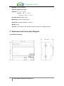
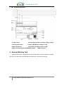
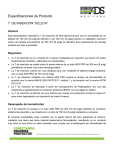
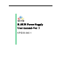
K-BUS Power Supply
User manual-Ver. 1
KP/D30.640.1
Green Life in GVS
Contents
1.
2.
3.
4.
2
Introduction ................................................................................................................... 3
Technical Parameter .................................................................................................... 3
Dimension and Connection Diagram ...................................................................... 4
Normal Working Test ................................................................................................... 5
K-BUS dimmer module user manual ver. 1
Green Life in GVS
1. Introduction
EIB/KNX power supply produces and monitors EIB / KNX system voltage. The bus
line is decoupled from the power supply with the integrated choke.
The power supply is connected to the bus line with a bus connection terminal. A reset
is triggered by pressing the reset push button and lasts 22 seconds (regardless of the
duration of the push button action).The bus line disconnected from the power supply and
the devices connected to this bus line are returned to their initial state. If the line should be
disconnected for a longer period, the bus connection terminal must be removed from
power supply.
A 30V DC auxiliary voltage is made available via an additional connection terminal.
This voltage can be used to supply a further bus line (in connection with a separate
choke).
2. Technical Parameter
Power supply: Input voltage: 95V ~255 Vac,47~63Hz
Power loss: <6 W
Efficiency: 75%
Output: EIB/KNX output (DPSU): 1 line with integrated choke
EIB/KNX nominal voltage: 30 V DC +1/–2 V, SELV
Auxiliary voltage output: 1 (without choke)
Auxiliary voltage: 30 V DC +1/–1 V, SELV
EIB/KNX nominal current:
(Total of EIB/KNX and auxiliary voltage output) 640 mA, short-circuit-proof
Sustained short-circuit current: < 1.3 A
Mains failure back-up time: >200ms
Operating/Display:
Green LED ―ON‖: output voltage is OK;
Red LED ―I>Imax‖: overload or short circuit
Reset push button: reset at the EIB / KNX output (starts when the
push button is pressed and lasts 22 seconds);
Red LED: Reset at the EIB/KNX output.
Connection: power supply: 3-srew terminals
Cable cross-section: single-core 0.2—4.0mm 2
Multi-core 0.2—2.5mm 2
EIB/KNX output: Bus connection terminal (black/red)
Auxiliary voltage output: connection terminal (yellow/grey)
3
K-BUS dimmer module user manual ver. 1
Green Life in GVS
IP Grade: IP 00, EN 60529
Ambient temperature range:
Operation: – 5 °C ~ + 45 °C
Storage: – 25 °C ~ + 55 °C
Transport: – 25 °C ~ + 70 °C
Housing & Color: plastic, white
Mounting: On 35mm mounting rail
Dimension: 90×108×70.56mm(H×W×D)
Weight: 0.2kg
CE norm: In accordance with the EMC guideline and the low voltage guideline
3. Dimension and Connection Diagram
◆ Dimension drawing:
4
K-BUS dimmer module user manual ver. 1
Green Life in GVS
◆
Connection Diagram:
1. Label carrier
5.Connection terminal (auxiliary voltage output)
2. Reset push button
6.Green LED(output voltage is ok)
3.Red LED (Reset)
7.Red LED(overload/ short circuit)
4. Bus connection terminal (EIB/KNX output)
8.Mains supply
4. Normal Working Test
Switch on the mains voltage once the device has been correctly installed, the green
LED ―ON‖, all other LEDs are switched off, the device is functioning correctly.
5
K-BUS dimmer module user manual ver. 1