1
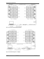
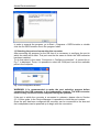
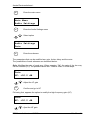
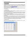
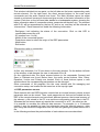
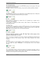
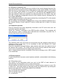
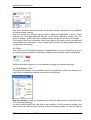
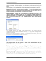
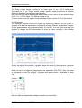
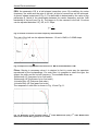
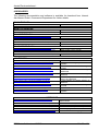
DSPController
PC Remote control for MA series D
Software v2.4
Firmware v1.1.x.x
Pol.Ind.Norte-Perpinyà,25
08226 TERRASSA (Barcelona-SPAIN)
[email protected]
www.master-audio.com
User’s Manual
February 09
Amate Electroacústica,s.l.
1.INTRODUCTION
This manual is aimed to describe all the installation and operation instructions related
to the DSPController module. This module is a built-in feature in all the speaker
systems of the MA series version “D” by Master-Audio. If specific information about a
certain model is required, please refer to the User’s Guide of the model itself.
In order to proceed with a quick start-up of the system, consider also reading the
“DSPController Quick Installation Guide”.
This manual describes the features of the following product versions:
Software DSPController: v2.4
Firmware DSPController: v1.1.x.x
Should you own different product versions, there may be differences between the
actual product and the description written here.
1.1.Components of the system
1.1.1.The DSPController module
The DSPController module is built in every MA series version D cabinet, and has
three main functions:
1) Carry out the digital audio signal processing (by means of the DSP) before routing
the signal to the amplifiers: filtering, equalization, limiting, etc.
2) Allow the user to modify the basic parameters of the DSP, thanks to the control
module on the back panel of the acoustic enclosure (LCD and keypad).
3) Provide with a connection interface which allows the remote control of the DSP
parameters of each system from a PC, using the supplied software.
Fig. 1: Built-in DSPController control panel
1.1.2.The DSPController Software
This software is a PC application, which provides the user with a Graphic User
Interface (GUI). With this interface, the user is able to manage the DSP parameters of
each speaker system remotely from the PC, thus modifying its frequency response. It
allows the connection of up to 64 systems simultaneously.
It is designed for PC with Windows operating systems (Win2000 and above).
1.1.3.The USB-485 converter
The systems with the DSPController module use the EIA communication standard
RS-485. A converter is needed in order to enable a regular PC to communicate using
this standard. The converter is connected to one of the computer’s USB port and,
after installing the adequate drivers, the computer will be able to connect to the RS485 bus.
This converter and the cables needed are supplied together with the speaker
systems.
DSPController.Version 1.2 ENG
Feb 09
2
Amate Electroacústica,s.l.
Fig. 2: USB-485 converter
1.2.Basic concepts
1.2.1.Factory Preset
All systems with the DSPController module are provided with at least one DSP
configuration stored in its memory, called factory preset. The “P01:BASIC” preset is
the default configuration and it is loaded the first time the system is connected. It is
optimized to obtain the maximum performance of the system in a general situation.
Presets cannot be erased from the memory, so they are always available as a
reference.
1.2.2.Remote control
The communication system used for the PC remote control is completely independent
of the audio reproduction path. Thus, it is not necessary to have a permanent
connection between the PC and the speaker systems in order to reproduce the
sound.
The remote control offers a lot of possibilities to adjust the system: change
parameters in real time, save several configurations, modify the DSP parameters on
each element separately, etc.
1.2.3.The data bus and the ID
The connection between the PC and the remote elements (the speaker systems with
the DSPController module) is attached to a common bus. The same cable brings the
data from the computer to the elements and vice versa. The speakers systems are all
connected in daisy chain to the bus, and the PC as well through the USB-485
converter.
Since all elements are identical and connected to the same bus, the bus master (the
PC) needs a mechanism to separately address the connected elements. This
consists of assigning a number to each element of the bus, which will be called ID.
The ID of each element of the bus is a unique number between 1 and 64 (0 is
reserved for the PC).
It is mandatory that each element connected to the bus has a unique ID assigned in
order to successfully connect the PC with the remote elements. How to assign an ID
is seen in Section 2.2.
DSPController.Version 1.2 ENG
Feb 09
3
Amate Electroacústica,s.l.
2.INSTALLATION
2.1.Interconnecting the system
To set the remote connection with the Master-Audio DSPController-equipped speaker
systems, it is necessary to interconnect them with the supplied data cable (networklike cable RJ-45 to RJ-45).
At the rear panel of each cabinet two RJ-45 female connectors are found, with the
label “RS-485 BUS”. The one used to receive the data is labelled as “IN” and the
other one, to send data to another system, is labelled as “LINK”. It is recommended to
follow this rule; however it is not necessary because the two connectors are internally
bridged.
Fig. 3. Connecting 4 MA210/D (audio, power supply and data)
The data signal must be sent from the PC located at the sound control to the
cabinets. The output of the USB-485 converter is equipped with a male DB9
connector, where a DB9 to female XLR3 cable (supplied) is connected. So, balanced
microphone cable with XLR connectors in combination with the supplied XLR3-RJ45
adaptors is enough to interconnect all the system. This is very convenient, since XLR
cables are very common in audio applications. The following interconnection
schemes are possible:
1) Daisy-chain connection: see Fig. 4 for details. The signal is brought from one
cabinet to the other. In this case, the following accessories are needed:
1xAdaptor RJ45 to XLR Female
2xAdaptors RJ45 to XLR Male
2) “Y”-connection: using a “Y” adaptor (see Fig. 5). The signal is divided in two
branches, one per channel. For this configuration, the following adaptors are needed:
2xAdaptors RJ45 to XLR Female
1x“Y”-Adaptor (1 XLR Male to 2 XLR Female)
All cable adaptors (RJ-45 to XLR as well as the “Y”) are supplied together with the
system’s “connection kit” and the USB converter.
DSPController.Version 1.2 ENG
Feb 09
4
Amate Electroacústica,s.l.
2.2.Assigning IDs to the cabinets
WARNING: Always perform this operation before connecting the system to the
PC.
Each cabinet to be connected to the system must have a unique identification (ID) in
the bus. If two or more cabinets with the same ID are connected to the system at the
same time, the connection will not be possible.
In order to assign the ID to a cabinet, go to the rear panel (DSPController module) of
each system. Section 3.2.1 describes in detail the procedure, but the main steps are
as following:
1) Power the system on and wait until the welcome message switches to the main
screen.
2) Press the “ID” key on the left of the keypad. The following screen will show:
Change Bus ID
ID:-3) With the “up” and “down” cursors change a valid ID between 1 and 64. It is strongly
recommended to choose an organised numeration and write it down. It will be then
easier to identify the cabinets later when working with the computer.
Change Bus ID
ID:01
4) Once the desired ID has been selected, confirm your selection by pressing “OK”.
The main screen will show again.
MA210D
ID:01
P01:BASIC
Repeat this operation in all cabinets to be connected, always assigning a different ID
to each one.
The ID is stored in the internal memory until it is changed again. In the case
that in the next installation the position of the cabinets is modified during
montage, a new identification progress may be needed.
Once the ID assignation has been carried out, the system is ready to be connected to
the computer. The next chapter covers how to setup the hardware on your computer.
DSPController.Version 1.2 ENG
Feb 09
5
Amate Electroacústica,s.l.
Fig. 4. Connection using XLR-RJ45 adaptors
Fig. 5. Connection using the “Y”-adaptor
DSPController.Version 1.2 ENG
Feb 09
6
Amate Electroacústica,s.l.
2.3.Installing the hardware
The first step is to directly connect the USB-485 converter to a free USB port of the
computer. The operating system will find a new hardware called “USB to RS422/485
adapter” and will launch the “Found New Hardware Wizard”. The drivers are found in
the supplied USB pen drive, so it must be inserted in a USB port during the
installation process.
The installation process follows these steps:
1) The converter is detected and the installation of the driver (called Prolific USB-toSerial Bridge) begins.
2) Sometimes the operating system prompts for connecting to “Windows Update”.
Select “No” and continue with “Next”.
3) Then select the option “Install from a list or specific location (Advanced)”
4) Select “Search for the best driver in these locations” and check the option “Search
removable media (floppy, CD-ROM …).
5) The driver has been installed. Now click “Finish”.
2.3.1.Checking the installation
In order to check that the converter has successfully been installed and the assigned
COM port number, go to the Device manager (under Control Panel, System
Properties, and Hardware). A new entry is shown, as following:
Ports (COM & LPT)
Prolific USB-to-Serial Bridge (COMx)
where “x” stands for the port number. Each time the converter is connected it will get
the same COM port number. See also Fig. 6.
Fig. 6 Device manager view
This entry is only active while the converter USB-485 is connected to the computer.
DSPController.Version 1.2 ENG
Feb 09
7
Amate Electroacústica,s.l.
2.4.Installing the DSPController software
Access to the USB pen drive supplied with the system. Under the folder “Software” a
DSPController-2.x-Setup.exe file is found. Double click on it and the setup wizard will
start. First you will be prompted for the desired installation language:
Follow the instructions of the wizard in order to set the installation directory and the
start menu location.
The wizard copies the files to the hard drive and finishes the process with a success
message:
DSPController.Version 1.2 ENG
Feb 09
8
Amate Electroacústica,s.l.
In order to execute the program, go to Start > Programs > DSPController or double
click the file DSPController.exe in the program folder.
2.5.Selecting the port and connecting the converter
After executing the program for the first time it is necessary to configure the port to
which the data will be sent. This port must be the same to which the USB converter
has been installed.
To do that select in the menu “Connection > Configure connection”. A screen like in
Fig. 7 is displayed. There, it is possible to select the COM port from all the available
ports in the computer.
Fig. 7. Port configuration window
WARNING: It is recommended to make the port selection process before
connecting the USB converter to the loudspeaker systems. The USB converter
must be only connected to the computer during this process.
If the port to which the converter is connected is unknown, please refer to Section
2.3.1 of this guide. In the Device Manager it is possible to check the port number.
Once the port has been configured the converter can be connected to the bus and
the loudspeakers can be powered up to begin with the connection.
DSPController.Version 1.2 ENG
Feb 09
9
Amate Electroacústica,s.l.
3.THE REAR PANEL
3.1.Description of the controls
The DSPController panel has the following look:
From left to right the main LCD screen, the indicator LEDs and the navigation keys
(keypad) and the shortcut keys are found. The functions of each module are
described here in the following sections.
3.1.1.LCD screen
The 2x16 character LCD screen informs about the status of the system and allows
accessing the menus. On system power-up looks like the following drawing:
MA210D
ID:01
P01:BASIC
The information on the main screen is:
- The model of the cabinet, on the top line to the left (MA210D in the example).
- The bus identification (ID), also on the top line.
- The current memory used and its name, on the bottom line.
On system power-up a welcome message is shown for approximately three seconds.
DSP Controller
by Master-Audio
During this time, the data are read from the memory and loaded to the DSP, while the
power supply of the amplifiers get stabilised. The loudspeaker will remain in mute
while this process is carried out. Also, it will not respond to instructions from the PC or
the keypad.
The LCD screen has a backlight which works on system power-up and switches
down after 20 seconds of inactivity (if any key of the keypad is pressed). In addition to
this, if the user has been navigating the menus and is not in the main screen, the
system will wait for 20 seconds of inactivity to get back to the main screen and switch
the LCD backlight off.
When the LCD backlight is off, it can be lit again by pressing any key of the keypad.
Then, the desired action can be performed.
DSPController.Version 1.2 ENG
Feb 09
10
Amate Electroacústica,s.l.
3.1.2.Menu navigation keys
Ok
There are 5 keys to navigate the menus: one arrow for each direction (up, down, left
and right) and a central key (OK). This central key is used to enter into the main
menu or to confirm changes.
The “up” and “down” cursors have two functions: to change a value when a
parameter is being modified and to select an option inside a submenu.
The “next” or “right” key is used to go inside a submenu (same as with the OK key).
The “back” or “left” key send the user back to the previous menu or to the main
screen.
3.1.3.Shortcut keys
ID
Mem
Mute
The shortcut keys are located to the right of the DSPController module and allow the
user accessing the most common functions in the menus.
The ID key goes directly to the change bus ID function. The Mem key gives the user
the list of the available memories to load to the DSP. Finally, the Mute key sets the
loudspeaker system in silence immediately.
The functions to which the shortcut keys lead, as well as the rest of them, are
carefully described in the following section:
3.2.Functions
3.2.1.Change bus ID
Using this function it is possible to change the ID number of the element, in order that
it can be identified in the bus (for connection with a computer). The possible values
are 1 to 64 or “--“. The double hyphen means that the connection is not enabled. This
function can be reached by pressing the shortcut key “ID”.
WARNING: Please remember that each system connected to the bus must have
a unique ID in order to have a successful link to the computer.
To assign the bus ID, follow these steps:
ID
Enter to the function
DSPController.Version 1.2 ENG
Feb 09
11
Amate Electroacústica,s.l.
Change Bus ID
ID:01
Select ID
Confirm and back to main screen
Ok
3.2.2.Mem (Memory List)
Pressing the Mem key, the user accesses directly to the Memory List menu. Here, all
available internal memories can be selected to be load its parameters (Gain, delay,
EQ, etc.) to the DSP.
Take the following process to load a new memory:
Mem
Enter the Memory List menu
Memory List
P01:BASIC
Select the desired memory
Confirm andback to main screen
Ok
3.2.3.MUTE
This function (only accessible by the shortcut key with the same name) mutes the
loudspeakers until the Ok key is pressed, as shown in the example below:
Mute
MUTE the system.
System MUTED
OK to unmute
Ok
Cancel the mute and back to the main screen
3.2.4.Audio Settings Menu
Inside this menu, 4 different commands to modify the DSP parameters can be found,
as well as the option to save the modified configuration to a memory.
DSPController.Version 1.2 ENG
Feb 09
12
Amate Electroacústica,s.l.
Ok
Enter the main menu
Main Menu
Audio Settings
Ok
Enter the Audio Settings menu
Select option
Audio Settings
Gain
Ok
Enter the submenu
The parameters that can be modified are: gain, limiter, delay and the mute.
The possibilities of each submenu are described below:
Gain: Modifies the gain of each way. When pressing “Ok”, the gain of the low way
can be modified (LF). The possible values are -12dB to +6dB, in 0.5dB steps.
Gain
LF: +00.0 dB
Adjust the LF gain
Ok
Confirm and go to HF
Following that, appears the option to modify the high frequency gain (HF).
Gain
HF: +00.0 dB
Ajust the HF gain
DSPController.Version 1.2 ENG
Feb 09
13
Amate Electroacústica,s.l.
Ok
Confirm
Back to previous menu / main screen
Limiter: This command allows adjusting the limiter depending on each application
requirements. He default value is 0dB (low and high frequency), which means that the
loudspeaker is delivering its maximum power without distortion.
A value down to -20dB below the maximum power can be set here, in 0.5dB steps
Limiter
LF: +00.0 dB
Adjust the LF limiter
Ok
Confirm and go to HF
Next, the screen to repeat this action but this time with the high frequency is shown.
Limiter
HF: +00.0 dB
Adjust the HF limitader
Ok
Confirm
Back to previous menu / main screen
Delay: The delay command adds a delay to the audio signal path. This is useful for
example to align satellites with subwoofers when they are not at the same position.
The maximum delay is 8.7m and can be set in 0.1m steps.
Delay
0.0 m
Adjust Delay
DSPController.Version 1.2 ENG
Feb 09
14
Amate Electroacústica,s.l.
Ok
Confirm
Back to previous menu / main screen
Mute: The mute command is used to separately mute the low frequency and high
frequency loudspeakers of the cabinet. This is useful to check the loudspeakers or
making measurements. When the mute is set to “Off”, the loudspeakers are active,
and are muted when set to “On”.
Mute
LF: Off
Switch LF Mute Off/On
Ok
Confirm and go to HF mute
Mute
HF: Off
Switch HF mute Off/On
Ok
Confirm
Back to previous menu / main screen
Save: After building a configuration with the previous submenus, it is possible to store
the changes to the internal memory of the system. To do that, select the Save
submenu under the Audio Settings menu. The following screen will show up:
Save
M01:-emptySelect target slot
Ok
Confirm
DSPController.Version 1.2 ENG
Feb 09
15
Amate Electroacústica,s.l.
Both an empty memory and a previously stored memory can be selected. In this
case, the data will be overwritten by the new ones. Next, the name of the new
memory must be set:
Save
M01:AemptyChange highlighted character
Ok
Next character / confirm
Previous character
After writing the new name, confirm it. The new memory is stored in the list, and can
be selected as explained in section 3.2.2, with the Mem key.
Save
M01:MyMemory
Ok
Confirm
Back to previous menu / main screen
3.2.5.Memory menu
The commands under this menu allow the user managing the internal memories of
the system. To enter this menu, just follow these steps (from the main screen):
Ok
Enter Main menu
Select Memory Menu
Main Menu
Memory
Ok
Enter Memory Menu
DSPController.Version 1.2 ENG
Feb 09
16
Amate Electroacústica,s.l.
Select option
Memory
Load
Ok
Enter the submenu
The available submenus are:
Load: Loads to the DSP the parameters stored in the selected memory. It is the
same function which is reached by the shortcut key “Mem”.
Memory List
P01:BASIC
Select memory to be loaded
Ok
Confirm
Back to previous menu / main screen
Empty user memories cannot be loaded. A warning screen will show up if this
situation happens:
Memory List
Memory is empty!
Copy: Copies a memory slot to another one, keeping the same name. To do that,
first the source must be selected. This can be either a preset or a not empty user
memory
Copy Source
P01:Factory1
DSPController.Version 1.2 ENG
Feb 09
17
Amate Electroacústica,s.l.
Select source slot
Ok
Confirm
After selecting the source, the target slot must be chosen. It must be a user memory,
either empty or not. If it is not empty, it will be overwritten
Copy Target
M01:-emptySelect target slot
Ok
Confirm
Back to previous menu / main screen
Rename: Changes the name of a user memory. The name of presets or empty
memories cannot be changed. Empty memories always have the description “-empty“. To change a memory name, follow these steps:
Rename
M01:MyMemory
Select memory to rename
Ok
Confirm
Next, use the cursors to set the new name to the memory:
Rename
M01:MyMemory
Change highlighted character
DSPController.Version 1.2 ENG
Feb 09
18
Amate Electroacústica,s.l.
Ok
Next character / Confirm
Previous character
After finishing his process, confirm the new name and go back to the main menu:
Rename
M01:NewName _
Ok
Confirm
Back to previous menu / main screen
Delete: This command deletes a slot from the system’s internal memory. Only not
empty user memories can be deleted (presets are protected). After deletion, the
memory slot appears in the list with “-empty-” in its description.
Delete
M01:MyMemory
Select slot to be deleted
Ok
Confirm
Back to previous menu / main screen
3.2.6.System Menu
Contains two functions related with the DSPController module system. To access this
submenu:
Ok
Enter Main menu
Select System Menu
DSPController.Version 1.2 ENG
Feb 09
19
Amate Electroacústica,s.l.
Main Menu
System
Ok
Enter System Menu
Select option
System
Change Bus ID
Ok
Enter the submenu
Change Bus ID: Allows changing the identification number of the element in the bus
(ID). Is the same function reached with the shortcut key ID, explained in section 3.2.1.
Change Bus ID
ID:01
WARNING: Please remember that each system connected to the bus must have
a unique ID in order to have a successful link to the computer.
Version Info: Shows the Firmware and internal memory (EEPROM) data versions. It
is only system information, so no action can be performed here.
DSPCon: 1.1.2.0
EEPROM: 1.0.0
Back to previous menu / main screen
DSPController.Version 1.2 ENG
Feb 09
20
Amate Electroacústica,s.l.
4.THE SOFTWARE
In order to get the maximum performance out of the loudspeaker systems with the
DSPController, it is recommended to manage them from a PC with the DSPController
software. This software is supplied with each system and also available for
downloading from the website www.master-audio.com.
With the software it is possible to remotely control the response of all the systems by
modifying the parameters of each DSP.
Please read carefully this chapter to learn all the possibilities offered by the remote
control software.
4.1.Communication
To link the PC with the speaker systems it is necessary to follow the process
described in Chapter 2 of this manual.
The communication is based on a multi-drop bus, where the PC acts as master and
the loudspeaker systems as slaves. To allow the PC identifying each of the systems
attached to the bus, it is necessary that each element has a unique ID (see Chapter 2
to learn more about ID assignation).
The data transmission standard used is the well-known RS-485 of the EIA. It is
specially indicated for industrial applications with multiple elements distributed along
a big distance.
The PC establishes a data interchange with the microcontroller of each loudspeaker
system, and each microcontroller feeds the parameters to the DSP depending on the
instructions received from the PC. Should the computer hang or the communication
be lost, the loudspeakers will still reproduce the sound because the communication
system is completely independent of the signal processing subsystem.
4.2.Software layout
After executing the program “DSPController.exe”, a presentation screen is shown.
After that, the main window is presented.
DSPController.Version 1.2 ENG
Feb 09
21
Amate Electroacústica,s.l.
This window is divided into two parts: on the left side are the boxes representing each
remote element. On the right hand, the direct access buttons to the most usual
commands and the audio controls are found. The Main Window cannot be either
closed or minimized, because it shows and give access to the basic information of the
system. Each box on the left hand side stands for a loudspeaker system, showing the
basic information about it (connection status, parameter set loaded, etc). The element
with ID 01 will be represented by the box 01 and so on, and they will be referred as
“element box”. Each element box holds the following information:
- Red/green Led indicating the status of the connection. Click on this LED to
connect/disconnect the unit
- ID (number from 1 to 64)
- Model of the connected system
- Drop-down menu to select the origin of the DSP parameters
- Mute button
- Edit button
Element box with no connection:
Element box with connection:
At first, only elements 1 to 32 are shown in the main window. On the bottom-left side
of the window, a tab changes the view to elements 33 to 64.
On the right-hand side, the direct access buttons to the commands Connect and
Save to Cabinets are found. Below them, the audio control buttons Gain, Delay,
Equalizer, Limiter and Polarity are located. Each of these buttons opens a new
window where the corresponding parameters can be changed.
Other commands of the program, like the ones related with file managing and
connection setup, are located on the menu bar at the top-right part.
4.3.DSP parameters source
Each element with the DSPController module has an internal memory where several
parameter sets can be stored. Then, each parameter set that can be loaded into the
DSP of the remote elements can have three different sources: the internal memory of
the element, a file stored in the PC or a real-time configuration made also in the PC.
Whereas the first source does not require the connection to a PC, the other two do.
It is possible to combine the different data sources. For example, in a 12-element
system it may be possible to have four elements using the internal memory, other
four using the real-time configuration and the last four getting the parameters from a
file.
In the following sections the particularities of each data source are described:
DSPController.Version 1.2 ENG
Feb 09
22
Amate Electroacústica,s.l.
4.3.1.Internal memory
The internal memories are stored in the EEPROM memory of each system. There are
two kinds of internal memories:
Presets (Px:Name): stored from factory, they cannot be either modified or deleted.
User Memories (Mx:Name): are created and can be modified by the user. Initially are
empty, so the cannot be selected until they are created.
Each memory is identified by a letter (M or P), followed by a number and a
description of 8 characters.
If this option is selected as data source, either Preset or User Memory, the
parameters are fixed.
4.3.2.Real Time
With this option it is possible to modify the DSP parameters of the remote element in
real time from the DSPController software. In order to do that, select the option RT:
Real Time in the drop-down menu of the elements desired.
Only the elements selected in mode “RT: Real Time” will be aware of the
parameter changes done on screen.
When one element is selected in RT mode, it will get immediately the parameter set
present on screen at that moment (under Gain, Delay, Equalizer and Limiter
controls).
4.3.3.File
From the computer it is also possible to load a parameter set previously stored in a
file. Just select the option “FI:Filedesc” in the drop-down menu of the desired
element.
The configurations stored in a file have always an 8-character descriptor, which is
shown when the file is loaded. The file name on the disk drive can be different to this
descriptor and as long as the operating system allows.
DSPController.Version 1.2 ENG
Feb 09
23
Amate Electroacústica,s.l.
4.3.4.Backup of parameter sets
The RealTime and File data sources are volatile at the remote element, because the
data from the PC are stored on the volatile memory of the system (RAM). This means
that if an element has loaded a File or RealTime configuration and is disconnected
from the mains, the next time it is powered up it will load the last internal memory
that was selected. When the elements are disconnected from the mains, they are
only able to keep the configuration stored in their internal memory, because this is
non-volatile (EEPROM).
The configurations stored in a file can be restored by connecting the PC to the remote
systems again and loading the file to them.
So it is strongly recommended to always store a copy of the desired parameter set in
the internal memory of each cabinet in order to avoid data loss in case of a mains
failure.
4.4.Connection process
Once all elements have been physically connected to the PC and to the main, the
connection process can begin.
Select the “Connect” command in the DSPController software. The computer will
scan the bus in order to identify which elements are connected to (by their ID). A
window depicting the process will show up.
The systems looks up for 64 boxes, but the process may be stopped at any time by
clicking on Stop. In this way it is not necessary to wait until element 64 if fewer
elements are connected.
Once the connection process finishes, each element with active link lights its led at
the element box in green. The model and the current memory used are also shown.
From now on, these elements are ready to get instructions.
Also, a single element may be connected to the bus by clicking on the “LED” located
in its control box.
4.5.Element options
In each element box has some control options available, as described in the following
sections:
4.5.1.Drop-down menu
The source of the parameters which are sent to the DSP of each element is
determined by the drop-down menu in each element box.
As seen before, the data sources can be three: internal memory (preset or user), File
or Real Time. This menu allows us selecting directly the data source, by clicking the
arrow on the right side. The following options are available:
-Px: for internal memory presets
-Mx: for internal user memory
-RT: for real time control
-FI: to load a file
DSPController.Version 1.2 ENG
Feb 09
24
Amate Electroacústica,s.l.
Only the not-empty internal memories are shown in the list, because it is not possible
to load an empty memory.
With the pointer the desired data source is selected (highlighted in blue). When
clicking on it, the parameters will be sent to the remote element, unless if the File
option is chosen. In this case, first a dialog window will ask for the file to be loaded.
If the option RealTime is selected, the current data in the audio control windows will
be selected to be transferred. If any of these audio controls has been edited, the base
configuration will be sent.
4.5.2.Mute
This button mutes the remote element, independently if it is set in RealTime or not. It
is a useful command when it is desired to adjust some elements while muting others.
While an element is muted, it is not possible to change its internal memories.
4.5.3.Edit/Memory Tools
The Edit button opens a new window where it is possible to select the data source,
load a file or manage the internal memories of the element.
Source selection: using the checkboxes (round) the data source is selected (Real,
File or Internal Memory).
In order to select RealTime, just click on its checkbox. If a file should be loaded, first
select it from the disk drive by clicking on the load button nearby. In case an internal
DSPController.Version 1.2 ENG
Feb 09
25
Amate Electroacústica,s.l.
memory is desired, click its checkbox and select a no empty memory from the list
below.
When clicking on Exit the data of the selected source will be transferred to the DSP.
Memory list: Below the “internal memory” checkbox, a list with all available internal
memories is shown, with both presets and user memories (also free slots). Here it is
possible to manage these memories (write, delete and rename).
Write a memory: To write data to a new memory, first select from the list the
TARGET memory for the data. Please note that it cannot be a preset, because they
cannot be overwritten. If a not empty memory is selected, it will be overwritten. Then
click on the “Write” button and a new window will show up to select the data
SOURCE.
The available options are “Real”, if the parameters in the current real time
configuration must be stored, or “Internal Memory”, if a copy of the existing internal
memories is desired.
Next the user will be prompted to introduce a name for the new memory. This is the
8-character description that will identify the memory.
After clicking Accept, the new memory is stored at the remote element and the
program goes back to the Memory Tools window. At this moment the new memory is
in the list and ready to be selected.
Delete a memory: If a user memory should be deleted from the internal memory,
select it from the list and then click on “Delete”. Please note that only not empty user
memories can be deleted. After the data transmission the memory is deleted and now
appears in the list as “-free-“.
Rename a memory: To rename a memory, follow the same procedure as for delete.
Select first from the list the memory (user, not empty) to rename and click on
“Rename” button. The user will be prompted to introduce the new name.
DSPController.Version 1.2 ENG
Feb 09
26
Amate Electroacústica,s.l.
Enter the new name (max. 8 characters) and click on “Accept” to confirm the
changes. After that the memory is available in the list with the new name.
4.6.Adjusting the DSP parameters
With the audio control buttons the response of the connected elements can be
modified, by sending new parameter values to their DSPs.
It is important to remember that only the elements in RealTime mode will be aware of
the changes made. When an element is set in RealTime mode, it will receive the
current parameter set visible in the Gain, Delay, Limiter and Equalizer windows.
4.6.1.Gain
The Gain control allows the user adjusting the gain of the low way and the high way
of the loudspeaker system. Two slide potentiometer-like controls are used. The
adjustment can be made from -12 to +6dB in 0.5dB steps. By default both controls
are set to 0dB. A Mute control for each way is available too.
To learn more about the bypass function please refer to section 4.6.5 of this manual.
4.6.2.Delay
DSPController.Version 1.2 ENG
Feb 09
27
Amate Electroacústica,s.l.
The Delay control inserts a delay to the input signal of up to 25.5 milliseconds
(equivalent to 8.7 m). This is useful to align speaker systems that are at different
distances because of installation requirements.
Both low and high ways are delayed with the same value, which can be selected from
0 to 8.7 m , in 0.1m steps. The default setting is 0m.
To learn more about the bypass function please refer to section 4.6.5 of this manual.
4.6.3.Equalizer
The equalizer module is aimed to correct the frequency response of the system. It
consists of 5 identical equalization cells, each allowing different equalization shapes.
On the graphic, each cell is represented by its number. You may click and drag this
number to change the EQ parameters, or enter the data manually in the number
fields.
On the top side of the window, a graphic draws the result of the frequency response
of each equalization cell, as well as the resulting response (thicker line in white).
Each cell can be configured independently as parametric EQ (PEQ), filter (low-pass
or high-pass) or shelf (lo or high). A bypass and delete button is available for each
cell.
Now the different equalization shapes available are described:
DSPController.Version 1.2 ENG
Feb 09
28
Amate Electroacústica,s.l.
PEQ: the parametric EQ is a bell-shaped correction curve. By modifying its centre
frequency, the width and the gain of the bell, all kind of corrections can be achieved.
A generic shape is depicted in Fig. 9. The bell width is determined by the value of the
parameter Q, which is the relationship between the centre frequency and the -3dB
bandwidth of the bell (see Fig. 8). The bigger is Q, the narrower is the bell. Q values
can be adjusted between 0.5 y 20, in 0.1 steps.
Q=
fc
BW
Fig. 8: Q factor in function of centre frequency and bandwidth
The gain of the bell can be adjusted between -12 and +12dB, in 0.25dB steps.
Fig. 9: Response of a parametric EQ centred in fc. BW is the bandwidth at -3dB.
Filters: filtering is necessary when it is desired to limit in some way the spectrum
reproduced by the loudspeakers. For each filter it is possible to select the type, the
shape, the order and the cut-off frequency. The available filters are:
-Butterworth LP (low-pass 1st or 2nd order)
-Butterworth HP (high-pass 1st or 2nd order)
-Linkwitz-Riley LP (low-pass 2nd order)
-Linkwitz-Riley HP (low-pass 2nd order)
The response of each filter is shown in Fig. 10 and Fig. 11.
st
Fig. 10: Response of the low-pass filters: 1 order Butterworth (red), 2
(blue) and Linkwitz-Riley (green) for fc=10 kHz
DSPController.Version 1.2 ENG
nd
order Butterworth
Feb 09
29
Amate Electroacústica,s.l.
st
Fig. 11: Response of the high-pass filters: 1
(blue) and Linkwitz-Riley (green) for fc=100 Hz
nd
order Butterworth (red), 2
order Butterworth
Low & High Shelf: a “Shelf” is a constant enhancement of a frequency range starting
on a selected frequency, called fc. The affected frequencies are the range below fc in
the case of a Low Shelf or the range above fc in case of a High Shelf. The
parameters that can be modified by the user are, apart from fc, the gain (between -12
and +12dB in 0.25dB steps) and the order (1st or 2nd), which determines how sharp is
the transition between the enhanced and not enhanced ranges. Fig. 12 and Fig. 13
show the response of each shelf.
st
Fig. 12: Low Shelf response: 1 order (red) and 2
st
nd
nd
Fig. 13: High Shelf response: 1 order (red) and 2
DSPController.Version 1.2 ENG
order (blue), for fc=1000 Hz
order (blue), for fc=1000 Hz
Feb 09
30
Amate Electroacústica,s.l.
To learn more about the bypass and “bypass all” functions, please refer to section
4.6.5 of this manual.
4.6.4.Limiter
The DSP built-in limiter is the responsible for controlling at each moment the power
delivered to the loudspeakers, in order to avoid damaging them. The default limiter
settings (0dB FS) allow the maximum power delivery without danger for the
loudspeakers.
However, it may happen that the user wants to limit the power of the system below its
maximum. In this case the limiter controls (slide potentiometers) can be used to
separately adjust the maximum power for the low and high ways.
The adjustment can be moved from the 0dB Full Scale down to -20dB FS, in 0.5dB
steps.
To learn more about the bypass function please refer to section 4.6.5 of this manual.
4.6.5.Polarity
It is possible to change the polarity to each element connected to the bus. The
polarity can be either positive (0º) or negative (180º). This feature is very useful when
cancellations are detected due to different location of subwoofers. But it should be
used very carefully, since may lead to critical sound cancellations and poor
performance of the system.
DSPController.Version 1.2 ENG
Feb 09
31
Amate Electroacústica,s.l.
4.6.6.Bypass
Each of the audio controls describes in the previous sections can be bypassed by
clicking the “bypass” button. The bypass cancels temporally the changes made while
it is active. The values are restored when the bypass button is clicked again. This is
useful to listen to the influence of the parameter modification at the loudspeakers.
Of course, the bypass influences only the elements that are set in RealTime mode,
and to the parameters belonging to the control window where they are located. For
example, the bypass at the Gain window only cancels the effect of the gain controls
low and high.
In the Equalizer window, an independent bypass for each equalization cell is
available, as well as a “bypass all” command, which cancels the effect of the five cells
at a time.
While the bypass is active, the control which is affected is disabled (changes colour to
light grey) and a small red led nearby the button us lighted. Please note that it is not
possible to save the RealTime configuration to the remote elements while a bypass is
active, because this could lead to confusion.
Hereby the gain window is shown before activating a bypass. The gain is -3.5dB for
the low way and 2dB for the high. When the bypass is active (right picture), both slide
potentiometers are disabled. Now at the remote elements the gain will be 0 for both
ways until the bypass is disabled.
4.7.Menus
The menus are located on the top right part of the program window, and contain the
file managing, connection and other useful commands
4.7.1.File Menu
New Processor Settings: This command deletes all contents in the audio parameter
windows (Gain, Delay, Equalizer, etc.). Useful to start a new project from scratch.
Open Processor Settings…: This command opens a previously created DSP
parameter file (*.dsp). The parameters are read from the file and translated into the
DSPController.Version 1.2 ENG
Feb 09
32
Amate Electroacústica,s.l.
audio control windows (Gain, Delay, EQ and Limiter). On the bottom left part of the
program window, the profile name of the file will be shown, as well as in the title bar
of all audio control windows. All elements in RealTime mode at the moment the file is
loaded will receive automatically the parameter set in the file.
Save Processor Settings: Saves the changes made to a file loaded by using the
previous command.
Save Processor Settings As…: Saves the current parameters in the audio control
windows to a file in the disk drive. The user will be asked for a “Profile” name, which
is an 8-character descriptor to identify the file when it is loaded to an element.
Exit: Exits the DSPController program. At this moment, all data which have not been
saved, either to the internal memory of the elements or to a file, will be lost.
The loudspeaker systems continue working independently of the connection with the
computer. At any time it is possible to connect the computer again and run the
program to re-establish the link.
4.7.2.Connection menu
Connect/Disconnect: Click on Connect to start the connection process between the
computer and the remote elements. During this process, the elements attached to the
bus are identified. The same will happen when clicking the “Connect” button on the
main window.
The system scans for 64 elements, but the process can be stopped at any time after
the existing connections have been established.
When the connection is active, “Disconnect” is shown instead. Clicking there the
connections with the remote elements are reset.
Refresh Connection: Works like the connect command, but can be used without
clicking on disconnect before. It updates the connected elements and their memory
list.
Configure Connection: Configures the communication port (COM) through which
the computer will be sending the data.
It is mandatory to select from the list the COM port in which the USB-485 converter
has been assigned. Remember that the converter must be connected to the computer
during this operation, in order that the right port appears in the list.
If the port number is unknown for the user, please go to your computer’s Control
Panel and double click on “System”. There select the Device Manager under the
Hardware tab. Under “Ports (COM & LPT)”, an entry called Prolific USB-to-Serial
Bridge (COMx) must exist, where “x” is the right port number.
4.7.3.Commands Menu
Set Cabinets in RT: This command is used to set several elements in RealTime at a
time. When executing this command, the following window shows up:
DSPController.Version 1.2 ENG
Feb 09
33
Amate Electroacústica,s.l.
From the active elements list select the elements to be set in RealTime mode (use
Control key for multiple selection). Clicking Accept will send the RealTime data to the
selected IDs.
Save to Cabinets: This option helps the user to store a real time parameter
configuration to the internal memory of several elements. The following window will
show up:
First of all, the destination IDs must be selected from the available cabinets. Then in
step 2 a name must be given for the memory. The last step is to select the slot to
which the memory will be stored (the same for all selected elements). If any of the
elements already has a valid memory in this slot, it will be overwritten by the new one.
After clicking “Accept” the data is transmitted. Once this process is finished, all the
selected cabinets are removed from RealTime mode and have the new memory as
current data set.
WARNING: Only elements which are in RealTime mode and not in MUTE are
available for this command. The rest will not appear in the list.
Load File to Cabinets: Use this command to load a parameter set of a *.dsp file to
several elements. In the emerging window select first the file to be loaded with the
Load button. Then select the IDs of the elements to which the file should be loaded
(use the Control key for multiple selection).
DSPController.Version 1.2 ENG
Feb 09
34
Amate Electroacústica,s.l.
Click on Accept and the file will be loaded to the selected IDs.
4.7.4.Windows Menu
This menu just gives access to the program windows that may be open. These can
be: Main Window, Gain, Delay, Equalizer and Limiter. If one is selected from this
menu, it will be activated and shown in the foreground.
4.7.5.Option Menu
Language: Allows changing the language of the user interface. Three languages are
available: English, Spanish and German.
4.7.6.Help Menu
Help Topics: Contains the help file about the DSPController commands.
About: Shows the program version and additional information.
DSPController.Version 1.2 ENG
Feb 09
35
Amate Electroacústica,s.l.
5.PRACTICAL EXAMPLES
In this chapter some examples on how to use the DSPController software in a real
application are given.
In these examples, a sound system consisting of 16 elements is assumed, with the
following configuration:
8 elements on left channel (IDs 01 to 08)
8 elements on right channel (IDs 09 to 16)
It is also assumed that all 16 systems have been successfully linked to the PC (green
led lit on the main window).
5.1.What should be kept in mind
In order that the modifications done with the software (Gain, Delay, EQ, Limiter and
Polarity) are transferred to the remote elements, they must be in RealTime mode.
When the RealTime mode is set for one or more elements, these get the parameters
currently visible under the audio control windows.
The data sources RealTime and File are volatile at the remote element. If the element
is disconnected from the mains, when it is powered again it will load the last internal
memory it used, and not the RealTime or File parameters. So it is strongly
recommended to always make a copy of the desired configuration to the element’s
internal memory.
5.2.Example 1
The following procedure will be followed: the left channel will be adjusted in RealTime
while the right channel is muted. Then, the configuration will be transferred to all the
cabinets and set as current. The steps to be followed are:
1) Set all elements in RealTime. In order to do that, use the command “Set Cabinets
in RT” and select all elements in the list.
2) After that set elements 09 a 16 in MUTE, so they will not interfere during
measurement/adjustment.
3) In the audio controls (Gain, Delay, Equalizer y Limiter) make the desired changes.
4) Unmute all the systems that were muted in step 2. Now it is possible to check the
response of the whole system with the new settings.
5) Use the command “Save to Cabinets” to store the current configuration to the
internal memory of all elements. In order to do that, select in the first column all
the elements, then give a name to the memory and finally select the target
memory slot. For this example choose “Example1” and slot 1. Accept to start the
data transfer. After that all elements will be set with the new memory (in this case
M01:Example1).
Following with this example, now it is also possible to store this configuration to the
computer’s disk to use it later. Just follow these steps:
6) Select in the menu “File > Save Processor Settings file…”.
7) Give a profile name (8 characters) when prompted. In this example write “File1”.
8) Name the file (for example “Manual Example 1.dsp” and click OK.
5.3.Example 2
Imagine now that with the same system as is Example 1 a new event must be
performed, but the hall conditions are different. Being the same system as in 1, it may
be a good idea to take the configuration done before as starting point:
DSPController.Version 1.2 ENG
Feb 09
36
Amate Electroacústica,s.l.
1) Load the file “My example 1.dsp” using “File>Open Processor Settings File…”.
Select the file and click OK.
2) Now the parameters contained in the file are loaded to the audio control windows.
3) Set all the elements in RealTime (like in example 1). If desired, one channel can
be muted.
4) Now all elements have received the parameters from the file and are set to
RealTime.
5) Readjust the parameters depending on the new conditions of the hall.
6) Save the configuration to the internal memory of all the systems, as described in
step (4) of example 1. Remember to remove all the mutes before doing that. Now
give the name “Example2” to the configuration and store it to slot 2.
7) Now all the elements are set to the new configuration, named M02:Example2.
8) Save the configuration as file following steps (6) to (8) of example 1. Give “File2”
as profile name and name the file as “My example 2.dsp”
5.4.Example 3
In this example the configurations done in the previous examples want to be
compared (one channel against the other). Example 1 will be set to left channel and
Example 2 to right channel. Two options are available, here the first:
1) Select in the element box of IDs 01 to 08 the memory M01:Example1 from the
drop-down menu.
2) Proceed in the same way with elements 09 to 16, but now choosing
M02:Example2.
The second option will be using the previously stored files, as following:
1) Use the command “Load File to Cabinets”, and select the file “My example 1.dsp”.
Select elements with ID 01 to 08 to load the file. After clicking on accept, the
configuration of these elements will be “FI:File1”.
2) Use the same procedure with elements 09 to 16, but now choosing the file “My
example 2.dsp”. Check that these elements now have “FI:File2”.
DSPController.Version 1.2 ENG
Feb 09
37
Amate Electroacústica,s.l.
6.RESOURCES
The following documentation and software is available for download from Internet.
Ask Master-Audio’s Commercial Department for further details.
MA206 ENGLISH
www.master-audio.com/download/MA-CAT206.pdf
www.master-audio.com/download/MA-MAN206115ENG.pdf
MA-206 brochure
MA-206 User’s manual
MAW115D ENGLISH
www.master-audio.com/download/MA-CAT115.pdf
www.master-audio.com/download/MA-MAN206115ENG.pdf
MAW-115 brochure
MAW-115 User’s manual
MA210D7 ENGLISH
www.master-audio.com/download/MA-CAT210.pdf
www.master-audio.com/download/MA-MAN210215ENG.pdf
MA-210 brochure
MA-210 User’s manual
MAW215D/2K ENGLISH
www.master-audio.com/download/MA-CAT215.pdf
www.master-audio.com/download/MA-MAN210215ENG.pdf
MAW-215 brochure
MAW-215 User’s manual
MAW218D7 ENGLISH
www.master-audio.com/download/MA-CAT218.pdf
www.master-audio.com/download/MA-MAN218ENG.pdf
MAW-218D7 brochure
MAW-218D7 User’s manual
PRESETS ENGLISH
www.master-audio.com/download/MA-PRESETENG.pdf
Presets for MA210/MAW215
ACCESORIES
www.master-audio.com/download/MA-ACCENG.pdf
www.master-audio.com/download/MA-FLYSTACK.pdf
www.master-audio.com/download/MA-STK210.pdf
www.master-audio.com/download/MA-STK210215.pdf
www.master-audio.com/download/MA-STK210218.pdf
www.master-audio.com/download/MA-FA106.pdf
www.master-audio.com/download/MA-FA156.pdf
www.master-audio.com/download/MA-BAR206.pdf
www.master-audio.com/download/MA-RP.pdf
www.master-audio.com/download/MA-RFA.pdf
Accessories user’s manual. ENGLISH
Flying and Stacking options between
systems
STK210 Kit for MA210 Stacking on
bumper
STK210/215 Kit for MA210 Stacking on
MAW215D
STK210/218 Kit for MA210 Stacking on
MAW218
FA10/6 Adaptor for MA206 flying with
MA210 and MAW215.
FA15/6 Adaptor for MA206 stacking on
MAW215.
BAR206 bars for MA206 stacking on
FLOOR
Rain kit
RFA4 Kit rubber feet for Line array
systems
SOFTWARE
www.master-audio.com/download/MA-DRIVERS.zip
www.master-audio.com/download/MA-SETUP.zip
www.master-audio.com/download/MA-DSPMANUAL.pdf
www.master-audio.com/download/MA-DSPGUIDE.pdf
www.master-audio.com/download/MA-MAPPINGENG.zip
www.master-audio.com/download/MA-SPLMANENG.pdf
DSPController.Version 1.2 ENG
Drivers for USB converter used with
DSPController
DSP Controller software
DSP Control Manual (Extended Guide).
DSP Control Manual (Fast Guide)
SPL & Mapping Software.
User's Manual of SPLMapping Software.
Feb 09
38