1
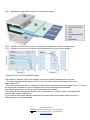
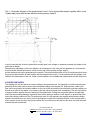
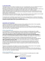
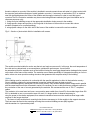
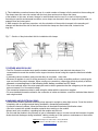
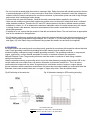
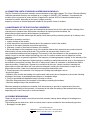
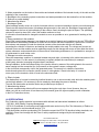
ECO PRODUCTION UK
SWEDEN Arlövsvägen 26 // 232 35 Arlöv // +46 (0)46 253000
UK 35 Firs Avenue // N11 3NE London // +44 (0)18 442244
www.ecoproduction.se
INSTALLATION MANUAL
MANUAL FOR INSTALLATION,USE AND MAINTENANCE OF ENERGY PHOTOVOLTAIC MODULES
INDEX:
1. INTRODUCTION...
2. GENERAL PRECAUTIONS
3. TECHNICAL DATA.
4. PROTECTION DIODES.
5. JUNCTION BOXES.
6. MOUNTING OF THE MODULE
7. FURTHER ADVICE ON USE
8. WARNINGS AND ELECTRICAL RISKS.
9. GROUNDING.
10. CONNECTION LIMITS OF MODULES IN SERIES AND IN PARALLEL.
11. MAINTENANCE OF PHOTOVOLTAIC GENERATOR POSSIBLE BREAKDOWNS
13. CERTIFICATIONS
1 INTRODUCTION
Eco Productions designs, produces and distributes its own brand of photovoltaic modules. Since it was
founded in 1996 the company has offered efficient modules of high-power and high quality. The
experience, professionalism and technical competence developed over the years allow Eco Production
to offer a wide range of modules in mono and poly-crystalline silicon, suitable for small installations up to
large photovoltaic parks.
Eco Productions mission is to position itself as a reference partner in the process of changing the management of
global energy through the production of photovoltaic modules able to satisfy current and future energy
requirements. To offer customers high power modules of high quality is a Company must. Eco Production is
becoming an established and recognized group on the international scene as a point of
reference among photovoltaic producers, offering a wide range of products qualitatively superior and economically
competitive to meet present and future needs of the entire sector.
2 GENERAL PRECAUTIONS
Carefully read all the installation and safety instructions set out in this document before carrying out any kind
of installation, connection and handling of the photovoltaic module. The advice given for one photovoltaic module
is applicable to other modules.
Eco Production declines any responsibility related to loss, breakage, deterioration or additional costs as a result of
wrongful handling of the product on the part of personnel not from this company.
ECO PRODUCTION UK
SWEDEN Arlövsvägen 26 // 232 35 Arlöv // +46 (0)46 253000
UK 35 Firs Avenue // N11 3NE London // +44 (0)18 442244
www.ecoproduction.se
• Keep the modules in their original packaging until the moment of installation.
• Do not drop the module or throw things at it. Do not step or walk on same
• Use the module only for the application for which it was intended.
• Do not dismantle the module or remove any part, label or piece, including the protection diodes installed by the
producer, unless otherwise specifically authorized.
• Keep the module in a horizontal position, without bending or twisting it.
• Do not concentrate sunlight or other sources of artificial light on the module.
• Do not perforate the frame of the module or subject it to pressure with other fixing systems.
• Installation must be carried out by qualified personnel only.
• Check the mechanical integrity of the module before installation.
• Only use undamaged modules.
• Do not leave a module open and not mounted. Capsizing could cause breakage of the glass. If the glass is
broken, the module cannot be used.
The electrical values are obtained from a standard measurement equivalent to an irradiance of 1000 W/m2,
air mass 1.5 spectral distribution and a cell temperature of 25 °C.The actual working conditions of the modules
once installed can be somewhat different from those of the laboratory, for this reason it is appropriate to know the
possible changes that can occur in order to make corrections as far as calculations are concerned. Whilst the
current generated by a photovoltaic module is proportional to the intensity of solar radiation, on the other hand the
voltage changes with the temperature of the cells. Both of these effects are shown in the graphs below.
3 Technical Data
The photovoltaic modules produced by Eco Production utilize high efficiency pseudo-square mono or
polycrystalline silicon cells for transforming solar radiation into direct current electrical energy.
The cell circuit is laminated using E.V.A. (Ethyl Vinyl Acetate) sheet as encapsulation, in a composite formed by
tempered glass on the upper side and a plastic polymer (TEDLAR) on the underside, resistant
to environmental agents and provided with electrical insulation.
The laminate is inserted in an anodized aluminum structure. The IP65 junction boxes, made with plastic resistant
to high temperatures, contain the cable glands, connecting terminals and protection diodes (by-pass diodes).
The frame has various holes for fixing the module to a support structure and to the floor whenever it
is necessary.
ECO PRODUCTION UK
SWEDEN Arlövsvägen 26 // 232 35 Arlöv // +46 (0)46 253000
UK 35 Firs Avenue // N11 3NE London // +44 (0)18 442244
www.ecoproduction.se
Fig. 1 - Represents schematically a section of a photovoltaic module.
Fig. 2. - Variation of curve I-V as a function of incident solar radiation at constant cell temperature.*
Fig. 3. - Variation of curve I-V as a function of cell temperature at constant incident radiation.*
* based on FVG 72-156 FVG 285M-MC model
The variation in electrical output of the modules in accordance with the temperature is as follows:
• The voltage decreases at the rate of 2.22 mV/°C for every cell in series in the module and for every
degree above 25°C.
• The current increases by about 17μA/cm2/oC of area of cells in parallel and for every degree over 25 °C.It must
be said that the temperature of the cell referred to does not coincide with the environmental
temperature, given that the cell warms up with the incident solar radiation.
The increase in cell temperature in relation to the air temperature is a function of their own characteristics
and that of the module construction.
As a function of the incident radiation, temperature and supply load, a photovoltaic module can work at
different values of current and voltage.
ECO PRODUCTION UK
SWEDEN Arlövsvägen 26 // 232 35 Arlöv // +46 (0)46 253000
UK 35 Firs Avenue // N11 3NE London // +44 (0)18 442244
www.ecoproduction.se
Fig. 4 - Schematic diagram of the characteristic curve I-V of a photovoltaic module together with a curve
of generated power and the two different working points, A and B.
It can be seen that the closer the photovoltaic module gets to the voltage of maximum potential, the greater is the
power that it obtains.
Summarizing, depending on the solar radiation, the temperature of the cells and the apparatus it is connected to,
the photovoltaic module generates a certain current and a fixed working voltage, whose
product indicates the power generated by the module. The technical data sheets of Eco Production products show
the physical characteristics of each module and the characteristic curves I-V in accordance with the incident solar
radiation and temperature of the cell. Under normal conditions it is probable that a photovoltaic module with mono-
4 PROTECTION DIODES
The shading of a cell can induce an inverse voltage in that particular cell. Consequently, it would consume power
generated by the other cells in series, with undesirable heating of the shaded cell. Such an effect, called a hot
spot, will be as great as the incident radiation on the rest of the cells and the less shall be the incident radiation on
this cell as a result of the shade. In an extreme case the cell could shatter from overheating. The use of protection
or by-pass diodes reduces the risk of heating of the shaded cells, limiting the current that passes through them
and in this way avoiding damage. In general, the modules having a number of cells equal to or greater than 33 in
series (the ranges produced by Eco Production start from 36 cells upwards) are supplied with protection diodes
placed in the junction box, as can be seen in the diagram of same in the following chapter. In the modules with a
lower number of cells in series, the by-pass diodes are not necessary in that the hot spot does not reach the level
at which the cells could break.
ECO PRODUCTION UK
SWEDEN Arlövsvägen 26 // 232 35 Arlöv // +46 (0)46 253000
UK 35 Firs Avenue // N11 3NE London // +44 (0)18 442244
www.ecoproduction.se
5 JUNCTION BOXES
The junction boxes of the modules are placed on the rear. As mentioned above, they are weatherproof boxes of
grade IP65 arranged in such a way to resist the elements, provided that the waterproofing seal is
maintained in the cable glands or seal where the cables pass through. In this regard, Eco Production declines any
responsibility arising from incorrect installation of these cables (in the case of modules supplied
without wiring).Each module has a single junction box for both terminals or a box for the positive terminal and
another one for the negative terminal. To ensure correct working of the modules, it will be necessary to comply
with the polarity of the connections.
The junction box covers bear an indicative design. They are opened by inserting a flat screwdriver into the related
tab in the direction indicated by the arrow, lightly pressing in the same direction to open it.
To close the cover it is sufficient to press it home. The cover has a flange that fixes it to the base of the junction
box while its internal part is being handled. This flange must not be cut. The junction boxes must not be subjected
to any type of pressure during the course of installation of the
module on a support structure, and no part must touch the junction box.
6 MOUNTING OF THE MODULE
During the mounting phase, the installer must respect all the regulations and provisions in force regarding
safety and construction, which specifically relate to photovoltaic systems.
Before mounting the system, make sure that you have taken into consideration all the static parameters of
construction using only mounting systems that meet the loads and stress foreseen at the place of installation
(e.g. snow, wind, hail, temperature, humidity).
Choice of the installation site
For the installation, it is recommended that you choose an area that is constantly exposed to sunlight
during all the months of the year, avoiding areas of shade and taking into consideration vegetation growth
in the vicinity. Also take into consideration vegetation that will grow tall and any high buildings.
In the northern hemisphere, in order to obtain maximum yields, the modules must be directed southwards,
whilst in the southern hemisphere they must be directed northwards. The most favorable inclination of
the system is in accordance with the latitude of the place of installation (for example, 30° in Italy). Different
angles will diminish the efficiency of the module, reducing the power production of the system
FVG ENERGY modules connected in series must be installed with the same orientation and angle; different
angles or orientation may cause reduction in the power generated because of the different quantity of
solar radiation that the modules receive.
The modules will produce maximum power when they are directed towards sunlight and it is advised
therefore, in case of mounting on fixed structures, to consider the best performance parameters that
are obtained during the winter season, because if adequate, they will be suitable even during the other
months of the year.
During the mounting phase, the installer must respect all the regulations and provisions in force regarding
safety and construction, which specifically relate to photovoltaic systems.
Before mounting the system, make sure that you have taken into consideration all the static parameters of
construction using only mounting systems that meet the loads and stress foreseen at the place of installation
(e.g. snow, wind, hail, temperature, humidity).
Choice of the installation site
For the installation, it is recommended that you choose an area that is constantly exposed to sunlight
ECO PRODUCTION UK
SWEDEN Arlövsvägen 26 // 232 35 Arlöv // +46 (0)46 253000
UK 35 Firs Avenue // N11 3NE London // +44 (0)18 442244
www.ecoproduction.se
during all the months of the year, avoiding areas of shade and taking into consideration vegetation growth
in the vicinity. Also take into consideration vegetation that will grow tall and any high buildings.
In the northern hemisphere, in order to obtain maximum yields, the modules must be directed southwards,
whilst in the southern hemisphere they must be directed northwards. The most favorable inclination of
the system is in accordance with the latitude of the place of installation (for example, 30° in Italy). Different
angles will diminish the efficiency of the module, reducing he power production of the system.
Angle of inclination of the modules
Eco Production modules connected in series must be installed with the same orientation and angle; different
angles or orientation may cause reduction in the power generated because of the different quantity of
solar radiation that the modules receive.
The modules will produce maximum power when they are directed towards sunlight and it is advised
therefore, in case of mounting on fixed structures, to consider the best performance parameters that
are obtained during the winter season, because if adequate, they will be suitable even during the other
months of the year.
Fig. 5 – How to measure the angle of inclination of the module
During the mounting phase, the installer must respect all the regulations and provisions in force regarding
safety and construction, which specifically relate to photovoltaic systems.
Before mounting the system, make sure that you have taken into consideration all the static parameters of
construction using only mounting systems that meet the loads and stress foreseen at the place of installation
(e.g. snow, wind, hail, temperature, humidity).
Choice of the installation site
For the installation, it is recommended that you choose an area that is constantly exposed to sunlight
during all the months of the year, avoiding areas of shade and taking into consideration vegetation growth
in the vicinity. Also take into consideration vegetation that will grow tall and any high buildings.
In the northern hemisphere, in order to obtain maximum yields, the modules must be directed southwards,
whilst in the southern hemisphere they must be directed northwards. The most favourable inclination of
the system is in accordance with the latitude of the place of installation (for example, 30° in Italy). Different
angles will diminish the efficiency of the module, reducing he power production of the system.
Angle of inclination of the modules
ECO PRODUCTION UK
SWEDEN Arlövsvägen 26 // 232 35 Arlöv // +46 (0)46 253000
UK 35 Firs Avenue // N11 3NE London // +44 (0)18 442244
www.ecoproduction.se
Eco Production modules connected in series must be installed with the same orientation and angle; different
angles or orientation may cause reduction in the power generated because of the different quantity of
solar radiation that the modules receive. The modules will produce maximum power when they are directed
towards sunlight and it is advised therefore, in case of mounting on fixed structures, to consider the best
performance parameters that are obtained during the winter season, because if adequate, they will be suitable
even during the other months of the year.
Installation
During the mounting phase, the installer must respect all the regulations and provisions in force regarding safety
and construction, which specifically relate to photovoltaic systems. Before mounting the system, make sure that
you have taken into consideration all the static parameters of construction using only mounting systems that meet
the loads and stress foreseen at the place of installation
(e.g. snow, wind, hail, temperature, humidity).
Choice of the installation site
For the installation, it is recommended that you choose an area that is constantly exposed to sunlight during all the
months of the year, avoiding areas of shade and taking into consideration vegetation growth
in the vicinity. Also take into consideration vegetation that will grow tall and any high buildings. In the northern
hemisphere, in order to obtain maximum yields, the modules must be directed southwards,
whilst in the southern hemisphere they must be directed northwards. The most favorable inclination of the system
is in accordance with the latitude of the place of installation (for example, 30° in Italy). Different angles will diminish
the efficiency of the module, reducing he power production of the system.
Angle of inclination of the modules
Eco Productions modules connected in series must be installed with the same orientation and angle; different
angles or orientation may cause reduction in the power generated because of the different quantity of
solar radiation that the modules receive. The modules will produce maximum power when they are directed
towards sunlight and it is advised therefore, in case of mounting on fixed structures, to consider the best
performance parameters that are obtained during the winter season, because if adequate, they will be suitable
even during the other
months of the year.
Installation
The installation procedure also includes the electrical part and therefore can be potentially dangerous if carried out
by unqualified personnel. Do not use modules of different makes in the same system. If the modules are
connected in series, the tension of the array cannot exceed the maximum tension of the system.
As a reference, the maximum number of modules can easily be calculated by dividing the “Max System Voltage” of
the module (present in the technical data of each Eco Production module) with the respective Voc
parameter (no load voltage) of the module. When the size of the system is worked out, the variation of the tension
must always be considered in relation to the temperature (Voc parameter diminishes with the increase in
temperature, and vice-versa).With the connection in series, which is done when a positive connector of a module
is connected to a negative connector of the subsequent module, the total tension of the entire array will be equal to
the
total of all the modules. In the case, instead, of a parallel connection, that is when the positive connectors of a
number of modules are connected to their negative connectors, the total current generated will be equal to the
sum of the current of all the modules connected in parallel. It is advisable to insert the fuses of each single array of
modules before connecting one array to another. When necessary, install isolation diodes in order to protect the
modules from damages caused by inverse current.The frame of the module is made of anodized aluminum and
ECO PRODUCTION UK
SWEDEN Arlövsvägen 26 // 232 35 Arlöv // +46 (0)46 253000
UK 35 Firs Avenue // N11 3NE London // +44 (0)18 442244
www.ecoproduction.se
therefore subject to corrosion if the module is installed in an environment where salt water is in direct contact with
the supports made with anothertype of metal (galvanic corrosion). If necessary, a seal made of PVC or stainless
steel can be fitted between the frame of the module and the support structure in order to avoid this type of
corrosion.The Eco Production modules may be mounted using different methods (the types listed below are for
reference purposes only):
1. Using corrosion inhibiting screws in the appropriate installation holes present in the module;
2. Using specific clamps and profiles on the long side of the frame of the module to connect the various
modules (oriented as in a portrait painting);
3. using specific clamps on the short side of the frame of the module to connect the various modules
Fig. 6 – Section of photovoltaic field for installation with screws
The module must be installed in such a way that air can freely move around it. In this way, the work temperature of
the cells can be reduced and, as a consequence, optimize the performance. It must further
be remembered that the modules must not be installed closing the small egg-shaped water drainage holes present
on the back of the frame of the module. The modules are not made specifically for integrated mounting on roofs or
walls, unless one uses special mounting structures that guarantee the complete safety of the building.
Cabling
All the cabling must be carried out in conformity with the specific regulations in effect in that particular country.
Correct cabling is obtained by using adequate connection cables that must be kept protected
from possible damages by making sure of the correct polarity. Only modules with the same voltage and in parallel
with the same tension must be connected in series.It is necessary to use a cable that has an adequate section for
the conduction of the sum of current generated by the modules. We recommend the use of “PV1 F” compliant
cables.
The conductor to be used must not have a cross-section area smaller than 4 mm2 For the models larger than 200
W, it is advisable to use a cross-section area of 6 mm2. If a larger section is deemed necessary to
carry the power to the relative equipment, then external connection boxes must be used that allow larger cable
sections for the longer stretches.
1. The frame of each module has 4 mounting holes that are necessary to fix the module to the support structure.
The frame must be fixed to the mounting rail using the corrosion inhibiting screws (M8) together
with the washers in 4 symmetrical points.
ECO PRODUCTION UK
SWEDEN Arlövsvägen 26 // 232 35 Arlöv // +46 (0)46 253000
UK 35 Firs Avenue // N11 3NE London // +44 (0)18 442244
www.ecoproduction.se
2. This installation procedure foresees the use of a certain number of clamps to fix the module to the mounting rail.
The clamps must not come into contact with the front glass and must not deform the frame
of the module. In this case, at least 4 clamps for each module must be used, 2 on each of the long sides.
According to specific environmental conditions, more clamps can be used in order to support heavier loads, for
example snow and strong wind.
3. With respect to the previous procedure, only the orientation of the module in respect to the mounting rail
changes and therefore the side of the frame on which the clamps are fixed: short side, instead of the
long side.
Fig. 7 – Section of the photovoltaic field for installation with clamps
7 FURTHER ADVICES ON USE
• The Eco Production modules have specific standard measurements (see technical data sheets). It is
recommended to mount the modules on the support structure chosen using the respective holes and suitable
screws.
• In mounting various modules, make sure that they do not shade each other.
• Whenever a regulator is used, it will be necessary to install it in an easily accessible position in order that the
user can check the control elements. When carrying out connections, respect the electrical polarity of all the
elements, connecting them in the following order: battery, modules and DC loads.
• The cross-sectional area of the wires employed must be able to guarantee that the voltage drop in the system
does not exceed 2% of its nominal voltage.
• The connection between modules is made using the cables with the connectors supplied.
• For more detailed information related to the connection of cables and diodes, consult the technical data sheet of
each single module.
8 WARNINGS AND ELECTRICAL RISKS
• A photovoltaic module generates electricity when exposed to sunlight or other light sources. Cover the surface
completely with an opaque material during installation, dismantling and handling.
• If protective fuses are utilized, follow the instructions in the attached technical specification sheet.
• Use tools covered with suitable insulation material when working on the module.
• Always work in dry conditions, regarding both the module and the tools.
• Do not install the module in the presence of gas or inflammable vapors, in order to avoid the formation of sparks.
• Avoid electrical discharges during installation, cabling, starting up of the system or maintenance of the module.
ECO PRODUCTION UK
SWEDEN Arlövsvägen 26 // 232 35 Arlöv // +46 (0)46 253000
UK 35 Firs Avenue // N11 3NE London // +44 (0)18 442244
www.ecoproduction.se
• Do not touch the terminals while the module is exposed to light. Equip the system with suitable protection devices
to prevent discharges of 30V DC or more on anyone. Given that in modules connected in series the voltages are
summed, whilst in parallel connections the currents are summed, a photovoltaic system can lead to high voltages
and currents, thus constituting a further danger.
• If the modules are used with batteries, follow all the safety recommendations supplied by the producer.
• Under normal conditions a photovoltaic module can produce more current and/or voltage than what is indicated
under standard conditions. Therefore the ISC and VOC values shown on the label of module features could be
multiplied by a factor of 1.25 to determine the maximum admissible values of installed components, with respect
to voltage current, cable diameter, fuses and measurement of the controls connected at the exit of the
photovoltaic generator.
• If installed on a roof, ensure that the module is fixed with a mechanical fixture. The roof must have an appropriate
level of fire resistance for the application.
• Eco Production modules are supplied with cables having the features indicated in the technical datasheet of each
module, with a working temperature range between –40 °C and 90 °C.• Fix the earth wire to the corresponding
hole (figure 10) in the frame using a mechanical fixing system like metallic nuts and bolts (not supplied)
9 GROUNDING
All module frames and mounting racks must be properly grounded in accordance with respective national electrical
code. Proper grounding is achieved by bonding the module frame(s) and all metallic structural
members together continuously using a suitable grounding conductor. The grounding conductor or strap may be
copper, copper alloy, or other material acceptable for use as an electrical conductor per respective
National Electrical Codes. The grounding conductor must then make a connection to earth using a suitable
earth ground electrode.
Attach a separate conductor as grounding wire to one of the 4mm diameter grounding holes marked ‘GR’ on the
module frame with a set of M4 screw, cup washer, flat washer, tooth washer, and M4 nut . This is to ensure
positive electrical contact with the frame. As a general rule, avoid direct contact of copper or copper alloyed
ground conductors with the aluminum module frame. All ground bond securing hardware in contact with either the
aluminum round condo module frame and / or copper or copper alloy actors’ must be stainless steel.
Fig 8-Positioning of the earth wire
Fig- 9 Schematic drawing for SPV module grounding
ECO PRODUCTION UK
SWEDEN Arlövsvägen 26 // 232 35 Arlöv // +46 (0)46 253000
UK 35 Firs Avenue // N11 3NE London // +44 (0)18 442244
www.ecoproduction.se
10 CONNECTION LIMITS OF MODULES IN SERIES AND IN PARALLEL
The Eco Production photovoltaic modules are manufactured to bear high voltages. The “Class II Electrical Safety”
certificate guarantees that they are insulated up to a voltage of 1000VDC. (IEC standard). Consequently the
modules can be connected in series until this voltage limit is reached. All Eco Production modules may be
connected in parallel, depending on the type of charge controller,
frequency converter or relative equipment suitable for that specific series of modules.
11 MAINTENANCE OF THE PHOTOVOLTAIC GENERATOR
Given its structure without moving parts and seeing that the internal circuit of the cells and the soldering of the
connections are insulated from the external environment by layered protective material, the
photovoltaic modules require a limited degree of maintenance.
In addition, Eco Production makes rigorous quality checks during all the production phases up to delivery to the
customer.
Maintenance operations consist of:
1. regular cleaning of the module;
2. visual inspection of any internal deterioration of the waterproof seals of the module;
3. checks on the state of electrical connections and wiring;
4. Ultimately, a check of the electrical features of the module.
1. Dirt accumulated on the transparent cover of the modules reduces their output and can provoke inversion
effects similar to those produced by shade. This problem can be particularly serious in the
case of industrial residues and bird droppings. The intensity of the effect depends on the opaqueness of the
residue. Layers of dust that reduce the intensity of the sun in a uniform manner are not dangerous and the
reduction in power is not generally significant. The frequency of cleaning depends, logically, on the intensity of the
soiling process.
It is appropriate to avoid deposits of bird droppings by installing as mall plastic antenna array on the high part of
the module to prevent their perching. Rain can, in many cases, reduce to a minimum or eliminate the need to
clean the modules. Cleaning can, in general, be carried out by the user. It simply consists of washing the
photovoltaic modules with water and a non-abrasive detergent, avoiding the accumulation of water on the
photovoltaic modules. Under no circumstances must pressure washers be used.
2. Visual inspection of the modules is for the purpose of finding any breakages such as:
• Any broken glass.
• Oxidation of the circuits and welding of the photovoltaic cells mostly due to dampness in the module following
breakage of the layers of packaging during transport or installation stage.
3. Carry out preventative maintenance every 6 months as follows:
• Check the fixing and state of the terminals of the cabling connecting the modules.
• Check the waterproofing of the terminal boxes.
Whenever waterproof problems are revealed, it will be necessary to provide for replacement of the parts
concerned and cleaning of the terminals. It is important to look after the sealing of the terminal boxes using,
depending on the case, new joints or a silicone sealant.
12 POSSIBLE BREAKDOWNS
Thanks to the rigorous quality control the photovoltaic modules undergo before being sold, breakages are
very infrequent.
The following can be checked on, which are mostly due to causes unrelated to the manufacturing process:
1. Breakage of module glass.
ECO PRODUCTION UK
SWEDEN Arlövsvägen 26 // 232 35 Arlöv // +46 (0)46 253000
UK 35 Firs Avenue // N11 3NE London // +44 (0)18 442244
www.ecoproduction.se
2. Water penetration on the inside of the modules and related oxidation of the internal circuitry of the cells and the
soldering of the connections.
3. Breakage to the connecting system connections and water penetration into the terminal box of the modules.
4. Dirtiness or partial shading.
5. Manufacturing defects.
1. Breakage of glass
Glass breakage usually occurs as a result of external actions, erroneous installation, impacts, stone-throwing,etc.
There have also been noted cases of breakage during transport to the work site. Breakage of tempered glass
often happens in the form of total splintering of the surface, clearly showing the point of impact. The splintering
reduces its output by about 30% even if the module continues to work.
It is therefore recommended to change the module as soon as possible so as to guarantee full working of the
system.
2. Damp penetration in the modules
Even if this is an infrequent damage, it can happen as a result of impacts and scratches on the rear TEDLARfrom
external attack. When damp penetrates as far as the cell circuits and their connections, it gives rise to corrosion
that reduces and manages to break the electrical contacts of the electrodes with the cell material,
preventing the collection of electrons and making the module unable to be used. The voltage and current are
reduced to zero and the module must be replaced promptly. As this damage will sooner or later affect the whole
system, whenever serious deterioration of the module is found during maintenance, it is preferable to arrange for
its replacement to avoid further costs.
3. Damage to module connections
Given the temperature variation, for example between day and night, a loosening in the cable connections of the
modules can occur. For this reason it is necessary to regularly inspect the connections (for example
at half-yearly intervals), arranging to tighten them if necessary.
During installation, check the waterproofing of the junction boxes by means of the cable glands.In the event of
water seeping into the connection box, its presence on the contacts causes a voltage drop
in the circuit and consequently a fall in the generated power. The remedy is to clean the connection
terminals and replace the connection junction boxes or cable glands, if found to be faulty. It is useful to
use a spray for the terminals, which is used in the electronics field.
4. Effect of shade
The shade effect or hot spot is caused by localized shade in one or various module cells while the remaining cells
receive high radiation. It is necessary to find a remedy by eliminating the cause of shading.
To avoid cell deterioration protective diodes are provided as per chapter 3.
5. Manufacturing defects
If present, manufacturing defects will become apparent during the early days of use. However, they are
rather rare, with an occurrence of less than one per thousand, given the rigorous quality control undertaken
in the Eco Productions factory.
13 CERTIFICATIONS
Eco Production supplies modules in accordance with national and international standards as follows:
• ISO 9001: 2008 Quality Company Management
• IEC 61215 certificate of conformity second edition with tests carried out by Euro Test Laboratory of Padua, an
entity recognized on an international level by TUV
• The photovoltaic modules produced by Eco Production respect the IEC61730 electrical safety standards, are
certified in Class A and comply with the Class II safety requirements assigned by the aforementioned
laboratory.
ECO PRODUCTION UK
SWEDEN Arlövsvägen 26 // 232 35 Arlöv // +46 (0)46 253000
UK 35 Firs Avenue // N11 3NE London // +44 (0)18 442244
www.ecoproduction.se