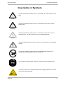
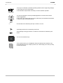
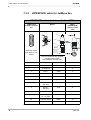
1
JL2 Servo Motors
JetWeb
Drives
Installation Manual
Article # 60868165 / Edition 2.07
December 2007 / Printed in Germany
Introduction
JetWeb
Edition 2.07
Jetter AG reserves the right to make alterations to its products in the interest of
technical progress. These alterations need not be documented in every single case.
This manual and the information contained herein have been compiled with due
diligence. However, Jetter AG assumes no liability for printing or other errors or
damages arising from such errors.
The brand names and product names used in this document are trademarks or
registered trademarks of the respective title owner.
2
Jetter AG
JL2 Servo Motors
Preceding Information
How to Contact us:
Jetter AG
Gräterstraße 2
D-71642 Ludwigsburg
Germany
Phone - Switchboard:
Phone - Sales:
Phone - Technical Hotline:
+49 7141/2550-0
+49 7141/2550-433
+49 7141/2550-444
Telefax - Sales:
E-Mail - Sales:
E-Mail - Technical Hotline:
Internet address:
+49 7141/2550-484
[email protected]
[email protected]
http://www.jetter.de
This installation manual is an integral
part of the JL2 servo motor series:
Model:
Serial #:
Year of construction:
Order #:
To be entered by the customer:
Inventory #:
Place of operation:
© Copyright 2006, 2007 by Jetter AG. All rights reserved.
Jetter AG
3
Introduction
JetWeb
Significance of this Installation Manual
This installation manual is an integral part of the JL2 synchronous servo motor series
•
•
and must be kept in a way that it is always at hand until the motor of the JL2
synchronous servo motor series will be disposed of.
If the motor of the JL2 synchronous servo motor series is sold, alienated or
loaned, this manual must be handed over.
In any case you encounter difficulties to clearly understand this installation manual,
please contact the manufacturer.
We would appreciate any suggestions and contributions on your part and would ask
you to contact us. This will help us to produce manuals that are more user-friendly
and to address your wishes and requirements.
This installation manual contains important information on how to transport, erect,
install, operate, maintain, and repair the motors of the JL2 synchronous servo motor
series.
Therefore, this person must carefully read, understand and observe this manual, and
especially the safety instructions.
Missing or inadequate knowledge of the manual results in the loss of any claim of
liability on part of Jetter AG. Therefore, the operating company is recommended to
have the instruction of the persons concerned confirmed in writing.
History
4
Revision
Comment
2.03
Original issue in English
2.04
Alterations as listed in appendix A (edition 2.04)
2.05
Alterations as listed in appendix A (edition 2.05)
2.06
Alterations as listed in appendix A (edition 2.06)
2.07
See Appendix A: "Recent Revisions", page 52
Jetter AG
JL2 Servo Motors
Preceding Information
Description of Symbols
Indicates a hazardous situation which, if not avoided, will result in death or serios
injury.
Danger
Indicates a hazardous situation which, if not avoided, could result in death or
serious injury.
Warning
Indicates a hazardous situation which, if not avoided, could result in minor or
moderate injury. This sign is also to warn you of material damage.
Caution
This sign indicates hazard of life due to electric shock caused by a high operating
voltage.
This sign is to indicate hazard of serious physical damage or death due to
accidentally touching dangerous parts of the device.
You are asked to wear goggles. Failure to comply may lead to bodily injuries.
This sign is to warn you of material damage due to applying hard blows or shocks
to the motor flange and shaft.
Jetter AG
5
Introduction
JetWeb
This sign is to indicate a possible impending situation which might bring damage
to the product or to its surroundings.
It also identifies requirements necessary to ensure faultless operation.
Important
You will be informed of various possible applications and will receive further
useful suggestions.
It also gives you words of advice on how to efficiently use hardware and software
in order to avoid unnecessary efforts.
Note
·/-
Enumerations are marked by full stops, strokes or scores.
Operating instructions are marked by this arrow.
Automatically running processes or results to be achieved are marked by this
arrow.
PC and user interface keys.
This symbol informs you of additional references (data sheets, literature, etc.)
associated with the given subject, product, etc. It also helps you to find your way
around this manual.
6
Jetter AG
JL2 Servo Motors
Table of Contents
Contents
1
Safety Instructions
9
1.1
Generally Valid Safety Instructions
9
1.1.1
1.1.2
1.1.3
1.1.4
1.1.5
1.1.6
Usage as Agreed Upon
Usage Other Than Agreed Upon
Who is permitted to operate the JL2 servo motor?
Modifications and alterations to the motor
Repairing and servicing the JL2 servo motor
Decommissioning and disposing of the JL2 servo motor
9
10
10
10
10
11
1.2
Ensure Your Own Safety
11
1.2.1
1.2.2
1.2.3
1.2.4
Malfunctions
Information Signs and Labels
Earthing procedure
Operating the holding brake ensuring personal safety
12
12
12
12
1.3
Residual Dangers
13
1.3.1
1.3.2
Hazards during Operation
Hazards after POWER is turned OFF
13
15
1.4
Instructions on EMC
15
2
Installation of the Servo Motor
17
2.1
Scope of Delivery
17
2.2
Important Notes
18
2.2.1
2.2.2
Ambient conditions
Avoiding damages
18
19
2.3
Mechanical Installation
21
2.4
Electrical Installation
23
2.5
Checking the Installation
24
2.6
Notes on Safety as regards the Installation
25
2.7
Notes on Safety as regards Commissioning
26
3
Operating Conditions
27
4
Type Designation
28
5
Physical Dimensions
30
6
Technical Data
31
7
Description of Connections
36
7.1
Motor Connection by means of the
Motor Connector Series SC
36
General remarks
Motor power cable with mating connector
36
37
7.1.1
7.1.2
Jetter AG
7
Table of Contents
JetWeb
7.1.3
7.1.4
7.1.5
Motor power cable for JetMove 2xx
Motor power cable for JetMove 6xx
Connection assignment of terminal box
38
40
42
7.2
Connection of the Resolver
43
7.2.1
7.2.2
7.2.3
Motor power cable with mating connector
Resolver cable for JetMove 2xx
Resolver cable for JetMove 6xx
43
44
45
7.3
HIPERFACE connection
46
7.3.1
7.3.2
7.3.3
HIPERFACE cable with mating connector
HIPERFACE cable for JetMove 2xx
HIPERFACE cable for JetMove 6xx
46
47
48
8
Maintaining the Motor
49
9
Troubleshooting
50
List of Appendices
Appendix A: Recent Revisions
Appendix B: Glossary
Appendix C: List of Illustrations
Appendix D: Index
8
52
53
57
58
Jetter AG
JL2 Servo Motors
Contents
1 Safety Instructions
1
Safety Instructions
1.1
Generally Valid Safety Instructions
The JL2 synchronous servo motor series JL complies with the safety regulations and
standards in force. Special emphasis was given to the safety of the users.
Of course, the user should adhere to the following regulations:
• relevant accident prevention regulations;
• accepted safety rules;
• EC guidelines and other country-specific regulations.
1.1.1
Usage as Agreed Upon
Usage as agreed upon includes operation in accordance with this installation
manual.
The JL3 series of synchronous servo motors belongs to the category of brushless
permanently excited precision motors of sine-shaped induced voltage.
The JL2 synchronous servo motors have explicitely been designed for being
torque, speed, and/or position controlled by specific servo amplifiers, such as
JetMove xxx made by Jetter AG. This motor has not been designed for direct
connection to the three-phase supply network. Direct connection to the mains
will result in destruction of the motor.
The JL2 synchronous servo motor series may only be operated within the
limits of the stated data, see chapter 6 "Technical Data", page 31.
The rated AC voltage of the motors is 170 V, respectively 310 V. The winding
isolation of the motors is rated at 560 V. During braking operation the DC link voltage
of the servo amplifier, however, can amount up to DC 850 V. Thus, the motor is
subject to the EC Low Voltage Directive.
The JL2 synchronous servo motor series has especially been designed as a drive for
machines that put high demands on dynamic performance and endurance. The JL2
servo motors may only be run under the operating conditions specified in this
installation manual; see chapter 3 "Operating Conditions", page 27.
The JL2 synchronous servo motors are installed in machines; they may only be
commissioned as devices integrated in specific plants.
The values rendered by the thermistor that is integrated into the motor
windings must be evaluated and monitored.
The JL2 synchronous servo motors are used for driving machinery, such as
conveyors, production machines, and handling machines.
Jetter AG
9
1 Safety Instructions
JetWeb
1.1.2
Usage Other Than Agreed Upon
The JL2 synchronous servo motor series must not be used in technical
systems which to a high degree have to be fail-save, e.g. ropeways and
aeroplanes.
If the JL2 synchronous servo motors are to be run under surrounding conditions,
which differ from the conditions mentioned in chapter 3 "Operating Conditions", page
27, the manufacturer is to be contacted beforehand.
1.1.3
Who is permitted to operate the JL2 servo
motor?
Only instructed, trained and authorised persons are permitted to operate the JL2
synchronous servo motor series.
Transport:
Only by personnel with knowledge in handling
electrostatically sensitive components.
Installation:
Only by specialists with training in mechanical and/or
electrical engineering.
Commissioning:
Only by specialists with extensive knowledge of, and
experience with, electrical engineering / drive
technology.
1.1.4
Modifications and alterations to the
motor
For safety reasons, no modifications and changes to synchronous servo
motors of the JL2 series and to their functions are permitted.
Any modifications to the motor not expressly authorised by the manufacturer will
result in a loss of any liability claims to Jetter AG.
The original parts are specifically designed for the JL2 synchronous servo
motor series. Parts and equipment of other manufacturers are not tested on
our part, and are, therefore, not released by us.
The installation of such parts may impair the safety and the proper functioning of the
motor.
Any liability on the part of Jetter AG for any damages resulting from the use of non
original parts and equipment is excluded.
1.1.5
Repairing and servicing the JL2 servo
motor
The synchronous servo motors of the JL2 series must not be repaired by the
operator. The synchronous servo motors of the JL2 series do not contain any parts
that could be repaired by the operator.
10
Jetter AG
JL2 Servo Motors
1 Safety Instructions
If a JL2 synchronous servo motor needs repairing, please send it to Jetter AG.
For information on servicing the JL3 synchronous servo motors refer to chapter 8
"Maintaining the Motor", page 49.
1.1.6
Decommissioning and disposing of the
JL2 servo motor
The environmental regulations for the respective country apply to decommissioning
and disposing of the JL2 synchronous servo motors on the operating company's
premises.
1.2
Ensure Your Own Safety
Disconnect the JL2 synchronous servo motor from the electricity mains to
carry out maintenance work. By doing so, you will prevent accidents
resulting from electric voltage and moving parts.
Please follow the information given in chapter 1.3 "Residual Dangers",
page 13.
Danger
Safety and protective devices, e.g. the guard, cover of the terminal box or
the thermal motor circuit-breaker must not in any case be shunted or bypassed.
Dismantled protective equipment, such as the fuses and the thermal
protection units of the motor, must be reattached prior to commissioning
and checked for proper functioning.
Do not wear protective gloves for fitting protective equipment. If the
motor shaft starts turning inadvertently, the protective gloves could get
caught in it.
The JL2 synchronous servo motor can become over 130 °C hot during
operation without being damaged.
For your own protection, do not touch the motor with bare hands (hazard of
burning) before measuring the temperature of the motor enclosure. The
machine manufacturer must see to an adequate protection against
accidental contact being installed.
Danger
Jetter AG
Before commissioning, the machine manufacturer must carry out a hazard
analysis of the respective machine and take adequate measures so that
inadvertent motions will not lead to personal injury and to material
damage.
11
1 Safety Instructions
JetWeb
1.2.1
Malfunctions
In case of failures or damages, disconnect the motor from the mains
immediately.
Please follow the information given in chapter 1.3 "Residual Dangers",
page 13.
Malfunctions or other damages are to be reported to an authorised person
at once.
Secure the JL2 synchronous servo motors against improper or inadvertent
use.
1.2.2
Information Signs and Labels
Writings, information signs, and labels always have to be observed and
kept readable.
Damaged or unreadable information signs and labels are to be
exchanged.
1.2.3
Earthing procedure
Please mind proper earthing of servo amplifier and servo motor.
Please ensure correct, low-resistance grounding of the frame by PE
reference potential in the control cabinet, as otherwise safety of persons
will not be guaranteed.
The frame should have a conductive, low-resistance connection with the
machine into which the servo motor has been integrated.
1.2.4
Operating the holding brake ensuring
personal safety
The holding brake can be controlled by the servo amplifier directly. In this case,
though, the safety of persons is not guaranteed, as suppression of the brake winding
is carried out without an additional external safety circuit.
If the holding brake is not controlled by the servo amplifier directly, an additional
circuit, e.g. by means of a varistor, must be provided. An operation of the holding
brake that is safe for personnel requires an additional normally open contact in the
brake circuit and a suppressor device, e.g. a varistor, for the brake circuit.
12
Jetter AG
JL2 Servo Motors
1 Safety Instructions
1.3
Residual Dangers
1.3.1
Hazards during Operation
HAZARD caused by high operating voltage!
Extremely hazardous voltages of up to DC 900 V may
occur!
Danger
Such voltages may result in muscle cramps, burns, unconsciousness, respiratory
standstill, or death.
Do not touch or undo electrical connections of the synchronous
servo motor while it is live.
The power connections may still be live, even though the motor is not
turning. The operating voltage can amount to up to 900 V.
There is a danger of electric arcing which is a danger to persons and to
contacts.
Danger
Check all live parts for protection by an electrical barrier.
Hot surface HAZARD!
The JL2 synchronous servo motor can heat up during operation. The surface
temperature of the motor can exceed 130 °C.
Danger
Do not touch the JL2 synchronous servo motor during operation or
during the cooling-off period following the switching off of the
amplifier.
If there are temperatures exceeding 60 °C, please install protection
against accidental contact.
Please make sure that no temperature-sensitive parts have been
connected or fastened to the motor.
Jetter AG
13
1 Safety Instructions
JetWeb
HAZARD in explosive gas atmosphere!
Danger
Do not apply the JL2 synchronous servo motor in potentially
explosive areas.
Exception: JL2 motors of the option E1 are apt for usage in the following
Ex zone: ATEX (Zone 2) II 3 G EEx nA II T3.
Hazardous mechanic force!
Warning
This servo motor can move mechanic parts or sharp edges. Therefore, failure or
malfunctioning of the amplifier or motor can be dangerous to persons or damage
the manufacturing plant. This should be prevented by adequate safety
precautions.
• One safety precaution is to install a second set of limit switches to interrupt the
power supply of the motor.
• Another safety precaution would be installing a guard.
Make sure that hazards to persons or material damage are precluded even
when the drive is rotating unintentionally.
Do not remove any guards.
Do not wear gloves, lest they should get caught in the rotating drive shaft.
Warning
Never touch a rotating drive shaft.
HAZARD by feather keys coming loose!
Some motor shafts come with a feather key. If such a shaft is not equipped with a
drive output element (e.g. gearwheel, sprocket, pulley), the feather key can come
loose when the shaft is spinning.
Warning
For this reason, wear goggles when the motor shaft is spinning.
14
Jetter AG
JL2 Servo Motors
1 Safety Instructions
1.3.2
Hazards after POWER is turned OFF
DANGER resulting from electric shock!
Capacitors of the servo amplifier can store dangerous voltages for at least 7
minutes after the power has been switched off.
The control and power connections may still be live, even though the motor is not
turning.
Danger
Do never disconnect the motor when it is under voltage.
Wait at least 7 minutes after switching off before disassembling the motor
or disconnecting the servo amplifier and the motor from the mains.
1.4
Instructions on EMC
The JL2 synchronous servo motor series has been designed for industrial use. It may
cause radio interferences when used in residential areas. It is operated at the
operator's own risk.
The noise immunity of a system corresponds to the weakest component of the
system. For this reason, correct wiring and shielding of cables is of paramount
importantance.
Important!
Measures for increasing immunity to interference:
Ground the panel and the frame according to chapter 1.2.3 "Earthing
procedure", page 12.
Connect the resolver respectively the HIPERFACE.
Connect the motor lines. The toroidal cores or the motor choke must be
placed near the servo amplifier; connect shields on both ends of the
cables.
Connect holding brake, if available, and connect shields on both sides of
the cables.
Jetter AG
15
1 Safety Instructions
JetWeb
If a motor power cable is used which includes cores for brake control, the
brake control cores must be shielded separately. Earth the shielding braid
on both ends. The shielding braid must be placed on both ends of the
applicable cables.
Follow the instructions given in Application Note 016 "EMC-Compatible
Installation of the Electric Cabinet" published by Jetter AG.
The following instructions are excerpts from Application Note 016:
On principle, physical separation should be maintained between signal
and power lines. We recommend spacings greater than 20 cm. Cables and
lines should cross each other at an angle of 90°.
All cables must be of a sufficient cross-section.
Shielded cables must be used for the following lines:
Analog lines, data lines, motor cables coming from inverter drives (servo
output stage, frequency converter), lines between components and
interference suppressor filter, if the suppressor filter has not been placed
at the component directly.
Shield cables at both ends.
Unshielded wire ends of shielded cables should be as short as possible.
The entire shield must, in its entire perimeter, be drawn behind the
isolation, and then be clamped under an earthed strain relief with the
greatest possible surface area.
The shield (impedance shielding) must, in its entire perimeter, be drawn
behind the shielding clamp of the metallised connector housing,
respectively of the EMC gland bushing, its greatest possible surface area
being clamped under a strain relief.
16
Jetter AG
JL2 Servo Motors
2.1 Scope of Delivery
2
Installation of the Servo Motor
2.1
Scope of Delivery
•
•
Synchronous servo motor of the JL2 series
Installation Manual
Mounting Accessories (not included in the scope of delivery)
•
•
•
Motor power cable, see chapter 7.1.2 "Motor power cable with mating connector",
page 37.
Resolver cable or HIPERFACE cable, see chapter 7.2.1 "Motor power cable with
mating connector", page 43, and chapter 7.3.1 "HIPERFACE cable with mating
connector", page 46.
Digital servo amplifier, e.g. JetMove 2xx or JetMove 6xx.
Note!
If you are not sure which accessories you will need:
The sales staff of Jetter AG will gladly assist you in the selection.
Jetter AG
17
2 Installation of the Servo Motor
2.2
JetWeb
Important Notes
Important!
Please read this installation manual before installing and
commissioning this servo motor.
Please keep to the terminal conditions (nameplate and installation
manual) and to the technical data of the motor, see chapter 6
"Technical Data", page 31.
Please check the assignments of servo amplifier and motor. Compare
the continuous rated current and the rated AC voltage of servo amplifier
and motor.
Carry out the wiring according to the electric connection diagrams
shown in a manual, e.g. in the operator's manual of the applied servo
amplifier JetMove 2xx or JetMove 6xx.
2.2.1
Ambient conditions
For the installation site of the JL2 synchronous servo motor, please give heed to the
following ambient conditions:
•
Ambient conditions:
-20 °C .. +40 °C
•
Maximum height of installation
position:
1,000 m above sea level
•
Relative humidity:
15 .. 85 % (non-condensing)
Important!
In case of a deviation from the surrounding conditions specified above,
derating might be necessary.
The synchronous servo motor of the JL2 series is not apt for installation in
the open air, nor in a corrosive or contaminated atmosphere. Such ambient
conditions will have negative effects on the service life of the motor.
18
Jetter AG
JL2 Servo Motors
2.2 Important Notes
2.2.2
Avoiding damages
Do not run the JL2 synchronous servo motor at the three-phase supply
network directly. The motor must be connected to a servo amplifier
designed for that purpose, e.g. a JetMove xxx.
Direct connection to the mains will result in destruction of the
motor.
Caution
Do not apply excess force when mounting the motor.
Do by all means refrain from applying hard blows or shocks to the
motor flange and shaft.
For fitting backlash-free output shafts with friction locking, please do by
all means only use the specifically designed tightening thread in the
motor shaft and warm up the power output elements, if possible.
Fitting the power output elements may only be carried out by
means of suitable tools. Please follow the instructions given by the
power output element manufacturers.
A special hint: Apply double-conical collets.
Make sure the clutch is aligned correctly. Please follow the instructions
given by the manufacturer of the clutch.
An offset will produce intolerable vibrations and will damage ball
bearings and clutch.
Caution
When using timing belts by all means observe the permissible radial
forces FR.
Radial loads exceeding the limits will significantly reduce the
service life of motors.
If a belt drive is used, the minimum permitted diameter of the pinion, for
example, is calculated as follows: dmin ≥ M0/FR x 2.
If possible, avoid axial load of the motor shaft.
Axial load will significantly shorten the service life of the motor.
When configuring the digital servo amplifier, make sure that the correct
number of motor poles and of resolver poles is set.
Faulty settings can result in overheating and destruction of the motor.
JL2 synchronous servo motor series:
• Number of motor poles: 6
• Number of resolver poles: 2
Please make sure there is sufficient heat dissipation, especially at the
flange side of the motor. Derate the motor output, if necessary.
During operation with rated data, the flange temperature of 65 °C
must not be exceeded.
The thermistor of the motor must be integrated into the monitoring
system of the servo amplifiers.
Jetter AG
19
2 Installation of the Servo Motor
JetWeb
All torque data have been determined for motors equipped with cooling
plates. For calculating the 3.5 mm thick cooling plates, the following
formula has been applied:
Length of cooling plate in mm = 2.5 x flange size in mm
Example:
Cooling plate for a JL2-0040-...-motor = 2.5 x 55 mm = 137.5 mm
The following cooling plate will result for JL2 motor types:
137.5 mm x 137.5 mm x 3.5 mm
20
Jetter AG
JL2 Servo Motors
2.3 Mechanical Installation
2.3
Mechanical Installation
Prior to installing the motor, check it for possible damages in transit
and/or storage.
Please do notify us without delay of damaged mechanical equipment,
as well as of corrosion damages to shaft or flange.
If there is a brake, release it first. Try to turn the rotor by hand; it must
react easily. Watch out for unusual scraping noises.
At manufacturing, the rotor of the motor is balanced electronically.
Before fitting the power output elements to the end of the shaft, remove
the corrosion protection that might still be covered with.
Do by all means refrain from applying hard blows or shocks to the
motor flange and shaft.
For fitting clutches, gear wheels or pulleys, please do by all means only
use the specifically designed tightening thread in the motor shaft, see
Fig. 1, and warm up the power output elements, if possible.
Spacer Washer
Fig. 1: Example: Fitting a power output element
For fitting power output elements use as far as possible only frictional
collets and clutches which are free from backlash.
Please pay attention to the correct alignment of the coupling (as
little unbalanced mass as possible).
A balance error produces vibrations and will damage ball bearings and
coupling.
Check power output elements (coupling, gearbox, pulley) for tight fit
and correct set-up.
Jetter AG
21
2 Installation of the Servo Motor
JetWeb
Please give heed to the admissible radial and axial forces. For this,
please, do also by all means read the chapter 2.2.2 "Avoiding
damages", page 19.
By all means avoid a hyperstatic arrangement of the motor shaft
bearings by using a rigid clutch and an external additional bearing (e.g.
in the gearbox).
The installation location must be free from conductive and corrosive
substances.
For encapsulated installation, please consult our application
department.
Protect the motors against liquids soaking into the bearing in case the
shaft end is installed upwards (design V1); refer to Fig. 2.
Type
IM B 5 (B5)
A-Side
IM V 1 (V1)
IM V 3 (V3)
B-Side
Fig. 2: Mounting Positions of JL2 Motors
Ensure unobstructed ventilation of the JL2 synchronous servo motor
and observe the maximum ambient and flange temperatures.
The permitted ambient temperature has been specified in chapter 3
"Operating Conditions", page 27. The maximum permitted flange
temperature during operation is 65 °C.
In order to remove gears, pulleys etc. please use a pulling device
according to Fig. 3.
22
Jetter AG
JL2 Servo Motors
2.4 Electrical Installation
Spacer Washer
Fig. 3: Removing a power output element
2.4
Electrical Installation
Have installation jobs carried out by qualified personnel only, see
chapter 1.1.3 "Who is permitted to operate the JL2 servo motor?", page
10.
Please check the assignments of servo amplifier and servo motor.
Compare the continuous rated current and the rated AC voltage of
servo amplifier and motor.
The cable diameter must be designed according to the continuous
rated current of the motor. Please do also observe the ambient
conditions, the mode of installation and the local regulations.
To connect resolver, HIPERFACE or power units, you can use
prefabricated cables available from Jetter, or opt for self-made cables.
Please refer to chapter 7 "Description of Connections", page 36.
All cables and pipes have to be run in a way that nobody gets
entangled in them. When laying lines, the bending radiuses must be
observed.
Carry out the wiring according to the electric connection diagrams
shown in the manual, e.g. in the operator's manual of the applied servo
amplifier JetMove xxx.
Check whether all ground cables are connected, see chapter 1.2.3
"Earthing procedure", page 12.
Jetter AG
23
2 Installation of the Servo Motor
JetWeb
For installation according to EMC, the chapter 1.4 "Instructions on
EMC", page 15 must be read and observed.
In addition, the explanations given in the operating manual of the
respective servo amplifier, e. g. JetMove xxx, are to be observed.
In particular, connect the shields according to the connection diagrams
given in the operating manuals of the servo amplifiers.
2.5
Checking the Installation
Check servo motor and servo amplifier wiring and connections by
means of the connection diagrams used.
A possibly existing holding brake must be checked for proper
functioning (attach DC 24 V, the brake must be released then).
Check to see whether the rotor of the motor can be turned easily (a
possibly existing brake must be released beforehand). Watch out for
possible unusual scraping noises.
Check to see whether all necessary protection measures against
accidental contact with live or moving parts have been taken.
Carry out any other checks specific to or required for your system.
Please do by all means set the correct number of motor poles and of
resolver poles.
Faulty settings can result in overheating and destruction of the motor.
JL2 synchronous servo motor series:
• Number of motor poles: 6
• Number of resolver poles: 2
Note:
For the digital servo amplifiers JetMove xxx by Jetter AG, the correct
motor type must be set. The settings of the motor and resolver pole
numbers will then be correct automatically.
Put the drive into operation according to the operating manual of the
servo amplifier.
When using multi-axis systems, put each drive unit (servo amplifier /
motor) into operation separately.
24
Jetter AG
JL2 Servo Motors
2.6 Notes on Safety as regards the Installation
2.6
Notes on Safety as regards the
Installation
HAZARD caused by high operating voltage!
Extremely hazardous voltages of up to DC 900 V may
occur!
Danger
Please, observe the following precautions in order to avoid injuries such as
muscle cramps, burns, unconsciousness, respiratory standstill or possibly death:
Have installation and maintenance jobs carried out by qualified personnel
only, see chapter 1.1.3 "Who is permitted to operate the JL2 servo
motor?", page 10.
Switch off the operating voltage.
Please take into account the information on residual dangers given in
chapter 1.3.2 "Hazards after POWER is turned OFF", page 15.
Before carrying out installation and maintenance jobs, isolate the JL2
synchronous servo motor and all connected devices from the mains (pull
out the mains plug).
Jetter AG
25
2 Installation of the Servo Motor
2.7
JetWeb
Notes on Safety as regards
Commissioning
HAZARD caused by high operating voltage!
Extremely hazardous voltages of up to DC 900 V may
occur!
Danger
Please, observe the following precautions in order to avoid injuries such as
muscle cramps, burns, unconsciousness, respiratory standstill or possibly death:
Have commissioning jobs carried out by qualified personnel only, see
chapter 1.1.3 "Who is permitted to operate the JL2 servo motor?", page
10.
Prior to commissioning, please do the following:
Reattach the dismantled thermistor and check it for proper functioning.
Reattach dismantled protective equipment and check it for proper
functioning.
This way, protection from moving parts of the machine will be achieved.
Protect the servo motor against accidental contact with live parts and
components.
Connect to the servo motor only devices or electrical components, e.g.
resolver, HIPERFACE or servo motor, that have been sufficiently
separated from the connected electric circuits.
Always carry out each commissioning, even a short functional test, with
correctly connected PE bus;
26
Jetter AG
JL2 Servo Motors
3
Operating Conditions
Operating Parameters
Transport
Temperature
-20 °C to 70 °C; maximum fluctuation: 20 °C per hour
Air humidity
Relative humidity up to 90 %, no condensation
Climatic Category
Category 2K4 to DIN EN 60721-3-2
Mounting in bearings
Storage Temperature
-20 °C to 70 °C; maximum fluctuation: 20 °C per hour
Air humidity
Relative humidity up to 90 %, no condensation
Climatic Category
Category 1K4 to DIN EN 60721-3-1
Storage
Only in original packing in a dry, dust-free and non-vibrating room
Storage Period
No limitation
Operation at Rated Data to chapter 6 "Technical Data", page 31
Ambient temperature
5 °C to 40 °C at an altitude of up to 1,000 m above sea level
Air humidity
Relative humidity 15 to 85 %, no condensation
Climatic Category
Category 3K4 to DIN EN 60721-3-3
Installation
•
Horizontal position (B5) to Fig. 2 on Page 22
•
If the module is operated at an altitude higher than 1,000 m above sea level,
derating will be required.
•
A clearance of at least 10 cm above and below the motor must be
maintained to provide proper air circulation.
•
1 % per °C in the range of 40 °C to 50 °C up to 1,000 m above sea level
•
At altitudes higher than 1,000 m above sea level and 40 °C:
Derating (currents and
torques)
6%
17 %
30 %
55 %
•
at 2,000 m above sea level;
at 3,000 m above sea level;
at 4,000 m above sea level;
at 5,000 m above sea level;
At altitudes higher than 1,000 m above sea level and a temperature
reduction of 10 °C per 1,000 m no derating is required.
Maximum permissible
flange temperature
65 °C + 10 %
Class of protection
IP 65
Insulation Class
F acc. to VDE 0530
EMC
Electro-Magnetic
Compatibility
Jetter AG
EMC is ensured if the following requirements as to filtering and shielding are
fulfilled: (cf. chapter 1.4 "Instructions on EMC", page 15)
•
Emitted interference to DIN EN 50081-1 and DIN EN 50082-2
•
Immunity to DIN EN 50082-2
27
4 Type Designation
JetWeb
4
JL
Type Designation
-
2
-
0040
-
8
-
3
R
V
B
P
S
C
F
E
Motor type JL
Frame size 2
Continuous stall torque in Ncm
Back EMF constant in V/kRPM
Thermostatic circuit-breaker
3 = Thermostatic circuit-breaker 145 °C *)
4 = Overtemperature protection PTC
6 = KTY83-110
Shaft tolerances
R - Concentricity tolerance of the shaft ends to DIN 42955R *)
Class of protection
V - Degree of protection IP65 without shaft seal *)
V2 = Degree of protection IP65 with shaft seal
B - Brake
_ = No brake *)
B = brake DC 24 V
P - Shaft
_ = Plain shaft *)
P = Feather key to DIN 6885
S - Electric connection
_ = Vertical position of the connector *)
S-A = Horizontal position of the connector in the direction of the motor shaft
S-B = Horizontal position of the connector against the direction of the motor shaft
S-X = Horizontal position of the connector; rotatable
C- Connector type
_ = Encoder connector series RC and motor connector series SC for JL2 through JL4,
JK4 through JK6, motor connector series SM for JL5 through JL8, JK7 *)
C1 = Encoder connector of the RC series and motor connector of the SC series (only for
JL5)
F = Encoder type
_ = Resolver 2-pin *)
F2 = HIPERFACE (SKS36 for JL2 or SRS50 for JL3 through JL8, respectively JK4 through JK7)
F3 = HIPERFACE (SKM36 for JL2 or SRM50 for JL3 through JL8, respectively JK4 through JK7)
E - Ex zone
E1 = Ex zone, ATEX (Zone 2) II 3 G EEx nA II T3
X - Other configuration (e. g. specific customer requirements)
Has been specified further in the product description
*)
If in an order no specifications have been made on optimum protection against
overtemperature and on extras to be provided, the features marked by bold *) are a
standard of the respective motor.
28
Jetter AG
X
JL2 Servo Motors
Ordering Instructions
•
•
Mating connectors and feather keys have to be ordered separately.
The JL2 series also includes motors equipped with HIPERFACE.
Selection Criteria
• Continuous stall torque Mo [Nm]
• Rated speed nn [rpm]
• Rotor inertia of motor and load J [kgcm2]
• RMS torque (calculated) Mrms [Nm]
For calculating the required servo motors and servo amplifiers, both the static and
the dynamic load have to be considered (acceleration and deceleration).
Word of Advice on Accessories
For the operation of synchronous servo motors, a motor cable, a resolver or
HIPERFACE cable, a servo amplifier and possibly a speed reducer are required.
Jetter AG employees would be glad to assist you in selecting the cables, the servo
amplifier and a suitable speed reducer.
Word of Advice on the Holding Brake
As an alternative, there are motors with integrated holding brake available. The
permanent magnet brake is controlled by DC 24 V; in de-energized condition, it will
block the rotor.
The holding brakes have been designed as standstill brakes!
They are not approved for permanent slowing down the motor as a part of the
operating mode!
Jetter AG
29
5 Physical Dimensions
JetWeb
5
Physical Dimensions
57
98
127
4°
Ø
50 x 50
Ø 9 k6
Ø
2,5
7
24
K (K1 = with brake)
74
63
4x ø 5,8
Ø 40 j6
17
55 x 55
54
102,5
63
62
4°
Ø
50 x 50
Ø 9 k6
Ø 40 j6
17
7
K (K1 = with brake)
Design with
resolver *)
K
K1
JL2-0020
JL2-0040
JL2-0060
JL2-0080
98
113
128
143
131
146
161
176
All dimensions in mm
63
55 x 55
Optional motor design with
feather key to DIN 6885-A 3x3x18
3
18
3P9
Ø 9 k6
24
Ø 40 j6
2,5
4x ø 5,8
Ø
74
*) No HIPERFACE available.
The connectors of the option S-X are positioned 7 mm higher.
Fig. 4: Mounting Dimensions of the JL2 Motor Series
30
Jetter AG
JL2 Servo Motors
6
Technical Data
Technical Data - JL2 Synchronous Servo Motor Series, Part 1
Motor Type
JL2-00208
JL2-002020
JL2-00408
JL2-004026
Motor Data
Continuous Stall
Torque
Mo
Nm
0.2
0.2
0.4
0.4
Continuous Stall
Current
Io
A
1.47
0.59
2.81
0.93
Back EMF Constant
KE
V/kRPM
8.2
20.5
8.6
26
Torque Constant
KT
Nm/A
0.14
0.34
0.14
0.43
Winding resistance:
phase to phase
RPh
Ω
8.66
54.07
2.59
26.25
Winding inductance:
phase to phase
LPh
mH
5.1
32.0
2.2
21.4
Electrical time constant
Tel
ms
0.59
0.59
0.85
0.82
Mechanical time
constant
Tmech
ms
4.89
4.89
1.77
1.97
Thermal time constant
Tther
min
10.0
10.0
15.0
15.0
Number of Motor Poles
pmot
-
6
6
6
6
Number of Resolver
Poles
pres
-
2
2
2
2
Rated Data
Rated Torque
Mn
Nm
0.18
0.19
0.35
0.36
Rated Speed
nn
RPM
6,000
4,500
6,000
4,500
Continuous Rated
Current
In
A
1.45
0.6
2.61
0.88
Peak Values
Peak Torque
Mmax
Nm
0.8
0.8
1.6
1.6
Peak current
Imax
A
6.3
2.5
12.1
4.0
Peak Speed
nmax
RPM
12,000
12,000
12,000
12,000
Mechanical Parameters
Rotor Inertia
J
kg*cm2
0.06
0.06
0.08
0.08
Weight without Brake
m
kg
0.9
0.9
1.06
1.06
Weight with Brake
mBr
kg
1.05
1.05
1.21
1.21
Axial load *)
FA
N
43
43
45
45
FR
N
225
225
237
237
Radial load
Jetter AG
*)
31
6 Technical Data
JetWeb
Technical Data - JL2 Synchronous Servo Motor Series, Part 1
Holding Brake for DC 24 V (optional)
Holding Torque
MBR
Nm
Supply voltage
UBR
V
Rated output
PBR
W
Rotor Inertia
JBr
2
DC 24 V (-10 % - +6 %)
11
kg*cm
2
0.068
Other Technical Data
Painting
Dull black, colour RAL 9005 (no stability to solvents, such as Trilene,
thinners, etc.)
Ball Bearing Service Life
≥ 20,000 operating hours
Thermal Motor Protection
Thermo switch 145 °C, optional PTC resistor, respectively NTC
resistor
All specified current and voltage values are RMS values.
*) Maximum allowed radial or axial force at 3,000 RPM. The axial force FA must not
become greater than a third of the radial force FR.
32
Jetter AG
JL2 Servo Motors
Technical Data - JL2 Synchronous Servo Motor Series, Part 2
Motor Type
JL2-00608
JL2-006031
JL2-006049
JL2-008025
Motor Data
Continuous stall torque
Mo
Nm
0.6
0.6
0.6
0.8
Continuous stall
current
Io
A
4.36
1.23
0.73
1.86
Back EMF constant
KE
V/kRPM
8.3
30.0
50.0
26.0
Torque Constant
KT
Nm/A
0.14
0.49
0.83
0.43
Winding resistance:
phase to phase
RPh
Ω
1.41
19.87
50.8
9.28
Winding inductance
phase to phase
LPh
mH
1.3
17.2
45.5
9.0
Electrical
time constant
Tel
ms
0.92
0.87
0.9
0.97
Mechanical
time constant
Tmech
ms
1.43
1.54
1.41
1.13
Thermal
time constant
Tther
min
20.0
20.0
20.0
22.0
Number of Motor Poles
pmot
-
6
6
6
6
Number of Resolver
Poles
pres
-
2
2
2
2
Rated Data
Rated Torque
Mn
Nm
0.53
0.55
0.55
0.72
Rated Speed
nn
RPM
6,000
4,500
4,500
4,500
Continuous rated
current
In
A
4.05
1.18
0.7
1.76
Peak Values
Peak Torque
Mmax
Nm
2.4
2.4
2.4
3.2
Peak Current
Imax
A
18.7
5.3
3.1
8.0
Peak Speed
nmax
RPM
12,000
12,000
12,000
12,000
Mechanical Parameters
Rotor Inertia
J
kg*cm2
0.11
0.11
0.11
0.13
Weight without Brake
m
kg
1.21
1.21
1.21
1.36
Weight with Brake
mBr
kg
1.36
1.36
1.36
1.51
Axial load *)
FA
N
47
47
47
48
FR
N
245
245
245
252
Radial load
Jetter AG
*)
33
6 Technical Data
JetWeb
Technical Data - JL2 Synchronous Servo Motor Series, Part 2
Holding Brake for DC 24 V (optional)
Holding Torque
MBR
Nm
Supply voltage
UBR
V
Rated output
PBR
W
Rotor Inertia
JBr
2
DC 24 V (-10 % - +6 %)
11
kg*cm
2
0.068
Other Technical Data
Painting
Dull black, colour RAL 9005 (no stability to solvents, such as Trilene,
thinners, etc.)
Ball Bearing Service Life
≥ 20,000 operating hours
Thermal Motor Protection
Thermo switch 145 °C, optional PTC resistor, respectively NTC
resistor
All specified current and voltage values are RMS values.
*) Maximum allowed radial or axial force at 3,000 RPM. The axial force FA must not
become greater than a third of the radial force FR.
Corner points
M [Nm]
Un
Mmax
Mz
Imax
Mo
Mx
Mn
nz
nn
no
-1
n [min ]
Fig. 5: Characteristic curve according to the JL2 synchronous servo motor
series
34
Jetter AG
JL2 Servo Motors
Corner Points: Characteristic curves for JL2 servo
motors, part 1
Motor Type
JL20020-8
JL20020-20
JL20040-8
JL20040-26
AC rated voltage Un
V
170
170
170
170
Rated torque Mn
Nm
0.18
0.19
0.35
0.36
Rated speed nn
RPM
6,000
4,500
6,000
4,500
Continuous stall torque
Mo
Nm
0.2
0.2
0.4
0.4
Peak torque Mmax
Nm
0.8
0.8
1.6
1.6
Peak torque Mx at nn
Nm
0.78
0.49
1.58
0.95
Idling speed no
RPM
24,040
9,760
23,150
7,690
Limit speed nz at Imax +
Mz
RPM
11,610
1,540
14,390
2,420
Limit torque Mz at Imax +
nz
Nm
0.78
0.79
1.57
1.58
Corner Points: Characteristic curves for JL2 servo
motors, part 2
Motor Type
Jetter AG
JL20060-8
JL20060-31
JL20060-49
JL20080-25
AC rated voltage Un
V
170
170
310
170
Rated torque Mn
Nm
0.53
0.55
0.55
0.72
Rated speed nn
RPM
6,000
4,500
4,500
4,500
Continuous stall torque
Mo
Nm
0.6
0.6
0.6
0.8
Peak torque Mmax
Nm
2.4
2.4
2.4
3.2
Peak torque Mx at nn
Nm
2.37
1.17
1.2
2.49
Idling speed no
RPM
23,960
6,780
6,600
7,650
Limit speed nz at Imax +
Mz
RPM
15,700
2,170
2,410
3,600
Limit torque Mz at Imax +
nz
Nm
2.36
2.38
2.35
3.17
35
7 Description of Connections
JetWeb
7
Description of Connections
7.1
Motor Connection by means of the
Motor Connector Series SC
7.1.1
General remarks
Important!
Alternative measures to avoid malfunctions of the control system and the motor:
Operate the brake via a separately shielded brake line. The distance
between brake line and motor power cable should be greater than 20
cm. This is the preferred solution.
Always connect brake lines to a separate power supply unit DC 24 V if
brake and motor lines are run together in one bunch of cables, and are
not separately shielded.
Important!
Measures to avoid oscillation and blocking of the motor:
Avoid mixing-up of phase conductors, resp. be sure to connect the
phase conductors according to pin assignment.
36
Jetter AG
JL2 Servo Motors
7.1 Motor Connection by means of the Motor
7.1.2
Motor power cable with mating connector
Note!
The suitable mating connector (female connector) of the synchronous servo
motor series JL2 can be ordered from Jetter AG by supplying the following
particulars:
Article # 15100070
Motor connector JL2-JL4/JK4-JK6 without brake
Article # 15100105
Motor connector JL2-JL4/JK4-JK6 with brake
Note!
The Jetter Motor power cable of the synchronous servomotor series JL2 can be
purchased from Jetter AG. It is confectioned with the matching motor connector
and can be ordered by the following cable confection numbers:
Without Brake:
Cable confection # 26.1
For JetMove 203 and JetMove 206
Cable confection # 26.1
For JetMove 601 through 610
With Brake:
Cable confection # 24.1
For JetMove 203 and JetMove 206
Cable confection # 24.1
For JetMove 601 through 610
Mating connector of the motor (solder side)
1
5
Solder Side
4
6
2
Fig. 6: SC series mating connector of the motor (internal thread
Jetter AG
M23)
37
7 Description of Connections
JetWeb
7.1.3
Motor power cable for JetMove 2xx
Motor power cable - Cable confection # 26.1
Connecting
terminals of
JetMove 2xx
4 x 1.5 mm2
The wires are
equipped with wire
end ferrules.
Shield
Shielded, highly
flexible 4-wire
cable with PE.
Mating
connector of the
motor (female,
solder side)
Solder Side
Cable
Adapter
65
Mating
Connector
Union Nut
JetMove 2xx
Sealing and
Strain Relief
Element
1 mm m
ax.
Mating Connector
Cable Strap
Motor Cable
Shielding Collar
18
360° All-round
Contact of the
Braided Shield
26
Individual
Cores
1
5
Solder Side
6
4
2
Connect both sides of the shield
with the greatest possible surface
area!
Use metallized housing only!
Pin
Wire Number
Signal
Pin
X62.U2
1
Phase 1
1
X62.V2
2
Phase 2
5
X62.W2
3
Phase 3
2
X62.PE
Yellow-green
PE conductor
All dimensions in millimeters.
38
Jetter AG
JL2 Servo Motors
7.1 Motor Connection by means of the Motor
Motor power cable - Cable confection # 24.1
Connecting
terminals of
JetMove 2xx
7 x 1.5 mm2
The wires are
equipped with wire
end ferrules.
Shield
Shielded, highly
flexible 6-wire
cable with PE.
Mating
connector of the
motor (female,
solder side)
Solder Side
Cable
Adapter
65
Mating
Connector
Union Nut
JetMove 2xx
Sealing and
Strain Relief
Element
1 mm m
ax.
Mating Connector
Cable Strap
Motor Cable
Shielding Collar
18
360° All-round
Contact of the
Braided Shield
Individual
Cores
26
1
5
Solder Side
4
6
2
Connect both sides of the shield
with the greatest possible surface
area!
Use metallized housing only!
Pin
Wire Number
Signal
Pin
X62.U2
1
Phase 1
1
X62.V2
2
Phase 2
5
X62.W2
3
Phase 3
2
X62.PE
Yellow-green
PE conductor
X10.BRAKE2
5
Brake +
6
X10.GND
4
Brake -
4
All dimensions in millimeters.
Jetter AG
39
7 Description of Connections
7.1.4
JetWeb
Motor power cable for JetMove 6xx
Motor power cable - Cable confection # 26.1
Shield
4 x 1.5 mm2
The wires are
equipped with wire
end ferrules.
Shielded, highly
flexible 4-wire
cable with PE.
The shield is
connected with
the servo
amplifier via PE.
Mating
connector of the
motor (female,
solder side)
Solder Side
Cable
Adapter
Mating
Connector
Union Nut
65
Connecting
Terminals of
JetMove 601
through JetMove
610
Sealing and
Strain Relief
Element
Shielding Collar
18
360° All-round
Contact of the
Braided Shield
26
Individual
Cores
1
5
Solder Side
6
4
2
Connect shield with the greatest
possible surface area!
Use metallized housing only!
Pin
Wire Number
Signal
Pin
X9.U2
1
Phase 1
1
X9.V2
2
Phase 2
5
X9.W2
3
Phase 3
2
X9.PE
Yellow-green
PE conductor
All dimensions in millimeters.
40
Jetter AG
JL2 Servo Motors
7.1 Motor Connection by means of the Motor
Motor power cable - Cable confection # 24.1
Shield
7 x 1.5 mm2
The wires are
equipped with wire
end ferrules.
Shielded, highly
flexible 6-wire
cable with PE.
The shield is
connected with
the servo
amplifier via PE.
Mating
connector of the
motor (female,
solder side)
Solder Side
Cable
Adapter
Mating
Connector
Union Nut
65
Connecting
Terminals of
JetMove 601
through JetMove
610
Sealing and
Strain Relief
Element
Shielding Collar
18
360° All-round
Contact of the
Braided Shield
Individual
Cores
26
1
5
Solder Side
4
6
2
Connect shield with the greatest
possible surface area!
Use metallized housing only!
Pin
Wire Number
Signal
Pin
X9.U2
1
Phase 1
1
X9.V2
2
Phase 2
5
X9.W2
3
Phase 3
2
X9.PE
Yellow-green
PE conductor
X9.Brake+
5
Brake +
6
X9.Brake-
4
Brake -
4
All dimensions in millimeters.
Jetter AG
41
7 Description of Connections
7.1.5
JetWeb
Connection assignment of terminal box
Connection Assignment of Terminal Box*)
Connection
Terminals of the
Amplifier
*)
42
Motor Terminal Box - Terminal Assignment
U2
Pin 1
Phase 1
V2
Pin 2
Phase 2
W2
Pin 3
Phase 3
PE
Pin 4
Protective Earth
Pin 7
Brake +
Pin 8
Brake -
alternatively to motor connectors
Jetter AG
JL2 Servo Motors
7.2 Connection of the Resolver
7.2
Connection of the Resolver
7.2.1
Motor power cable with mating connector
Note!
The resolver respectively HIPERFACE mating connector of the synchronous
servo motor series JL2 can be ordered from Jetter AG by supplying the following
particulars:
Article # 15100069
Resolver / HIPERFACE
The complete resolver cable connecting the servo amplifier series JetMove 2xx,
respectively JetMove 6xx and the synchronous servo motor series JL2 can be
ordered from Jetter AG.
It can be ordered by supplying the following cable confection number:
Cable confection # 23
For the servo amplifier series JetMove 2xx
Cable confection # 423
For the servo amplifier series JetMove 6xx
In case you prefer to fabricate the cables yourself, the following minimum
requirements must be met, also considering EMC:
• Max. cable length: 50 m
• Cable size: 3 x 2 x 0.14 mm2 + 2 x 0.5 mm2;
2 x 0.5 mm2 must be used for the thermal sensor.
• Twisted-pair cables with all-over shield must be used.
• The shield must be connected to the connector housings on both ends of the
cable with the greatest possible surface area.
Mating connector of the resolver (solder side)
Solder Side
8 9 1
7 12 10 2
6 11 3
5 4
Fig. 7: RC series mating connector of the resolver (internal thread M23)
Jetter AG
43
7 Description of Connections
JetWeb
7.2.2
Resolver cable for JetMove 2xx
Resolver cable of cable confection # 23
JetMove 2xx
(SUB-D connector
X61)
Shield
Motor (Resolver)
(female, solder
side)
Cable
Shield
Adapter
Union Nut
Sealing and
Strain Relief
Element
Shielding Collar
Attaching screws
must have a metric
thread!
360° All-round
Contact of the
Braided Shield
Individual
Connect shield with the greatest
possible surface area!
Use metallized housing only!
Pin
Signal
Core Colour
Pin
8
S1 (cosine +)
red
1
3
S3 (cosine -)
blue
2
2
S4 (sine -)
yellow
3
7
S2 (sine +)
green
4
1
R1R (exciter
winding +)
pink
5
6
R2L (exciter
winding -)
gray
6
9
Th1
(thermal sensor)
white
7
4
Th2
(thermal sensor)
brown
8
-
Unassigned
-
9 - 12
All dimensions in millimeters.
44
Jetter AG
JL2 Servo Motors
7.2 Connection of the Resolver
7.2.3
Resolver cable for JetMove 6xx
Resolver cable of cable confection # 423
JetMove 6xx
(SUB-D connector
X2)
Shield
Motor (Resolver)
(female, solder
side)
Cable
Shield
Adapter
Union Nut
Sealing and
Strain Relief
Element
Shielding Collar
Attaching screws
must have an inch
thread!
360° All-round
Contact of the
Braided Shield
Individual
Connect shield with the greatest
possible surface area!
Use metallized housing only!
Pin
Signal
Core Colour
Pin
4
S1 (cosine -)
red
1
8
S3 (cosine +)
blue
2
7
S4 (sine -)
yellow
3
3
S2 (sine +)
green
4
5
R1R (R +)
pink
5
9
R2L (R -)
gray
6
2
Th1
(thermal sensor)
white
7
6
Th2
(thermal sensor)
brown
8
-
Unassigned
-
9 - 12
All dimensions in millimeters.
Jetter AG
45
7 Description of Connections
JetWeb
7.3
HIPERFACE connection
7.3.1
HIPERFACE cable with mating connector
Note!
The resolver respectively HIPERFACE mating connector of the synchronous
servo motor series JL2 can be ordered from Jetter AG by supplying the following
particulars:
Article # 15100069
Resolver / HIPERFACE
The complete HIPERFACE cable connecting the servo amplifier series
JetMove 2xx, respectively JetMove 6xx and the synchronous servo motor series
JL2 can be ordered from Jetter AG.
It can be ordered by supplying the following cable confection number:
Cable confection # 723
For the servo amplifier series JetMove 2xx
Cable confection # 523
For the servo amplifier series JetMove 6xx
In case you prefer to fabricate the cables yourself, the following minimum
requirements must be met, also considering EMC:
• Max. cable length: 50 m
• Cable size: 5 x 2 x 0.25 mm2
• Twisted-pair cables with outer shield must be used; the signal lines must also
be twisted in pairs:
Sine + and reference sine
Cosine + and reference cosine
DATA - and DATA +
0 V and voltage supply
thermal sensor
• The shield must be connected to the connector housings on both ends of the
cable with the greatest possible surface area.
HIPERFACE mating connector (solder side)
Solder Side
8 9 1
7 12 10 2
6 11 3
5 4
Fig. 8: RC series HIPERFACE mating connector (internal thread M23)
46
Jetter AG
JL2 Servo Motors
7.3 HIPERFACE connection
7.3.2
HIPERFACE cable for JetMove 2xx
HIPERFACE cable of cable confection # 723
JetMove 2xx
(SUB-D connector
X61)
Shield
Motor
(HIPERFACE)
(female, solder side)
Cable
Shield
Adapter
Union Nut
Sealing and
Strain Relief
Element
Shielding Collar
Attaching screws
must have a metric
thread!
360° All-round
Contact of the
Braided Shield
Individual
Connect shield with the greatest
possible surface area!
Use metallized housing only!
Pin
Signal
Core Colour
Pin
-
Unassigned
-
1
-
Unassigned
-
2
7
Sine +
white
3
2
Reference sine
brown
4
8
Cosine +
green
5
3
Reference
cosine
yellow
6
6
DATA (RS-485)
gray
7
1
DATA +
(RS-485)
pink
8
4
0V
blue
9 *)
5
Power Supply
(7 - 12 volts)
red
10
9
Thermal sensor
black
11
Thermal sensor
-
12 *)
*)
Pin 9 and pin 12 are short-circuited
All dimensions in millimeters.
Jetter AG
47
7 Description of Connections
JetWeb
7.3.3
HIPERFACE cable for JetMove 6xx
HIPERFACE cable of cable confection # 523
JetMove 6xx
(SUB-D connector
X1)
Shield
Motor
(HIPERFACE)
(female, solder
side)
Cable
Shield
Adapter
Union Nut
Sealing and
Strain Relief
Element
Shielding Collar
Attaching screws
must have an inch
thread!
360° All-round
Contact of the
Braided Shield
Individual
Connect shield with the greatest
possible surface area!
Use metallized housing only!
Pin
Signal
Core Colour
Pin
-
Unassigned
-
1
-
Unassigned
-
2
1
Sine +
white
3
9
Reference sine
brown
4
3
Cosine +
green
5
11
Reference cosine
yellow
6
13
DATA (RS-485)
gray
7
5
DATA +
(RS-485)
pink
8
2
0V
blue
9
4
Power Supply
(7 - 12 volts)
red
10
14
Thermal sensor
black
11
7
Thermal sensor
violet
12
All dimensions in millimeters.
48
Jetter AG
JL2 Servo Motors
8
Maintaining the Motor
Motor maintenance is limited to the following work: Exchanging ball bearings and
occasionally cleaning the housing if it is very dirty.
Check the motor every 2,500 operating hours or at least once a year for
unusual ball bearing noises.
If there are unusual noises stemming from the ball bearings:
Put the motor out of operation and send it to Jetter AG for being
checked.
Do by no means disassemble the motor, as for reassembling, there are
specific instructions and settings to be observed.
The ball bearings are equipped with a grease packing adequate for
20,000 service hours under normal operating conditions.
After these 20,000 service hours, the ball bearings must be replaced.
For this, please send them to our company.
If there are unusual noises stemming from the motor (not the ball
bearings), the motor must be put out of operation and checked.
Use isopropanol or a similar cleaning agent for cleaning the motor
frame.
Do not use cleaning agents which contain solvents. On no account
immerse the motor in diluent or spray it with diluent.
Jetter AG
49
9 Troubleshooting
JetWeb
9
Troubleshooting
Table of Motor Faults
Type of Error
Motor will not start
Possible Cause
Troubleshooting
•
Servo amplifier not enabled
•
Apply ENABLE signal
•
Setpoint line interrupted
•
Check setpoint line
•
Motor phases mixed up
•
Connect motor phases correctly
•
Brake not released
•
Check brake control
•
Drive blocked
•
Check drive mechanism
Motor overspeed
•
Motor phases mixed up
•
Connect motor phases correctly
Motor chatters
•
Resolver line shielding interrupted
•
Replace resolver line
•
Gain factor too high
•
Use motor default values
•
Short-circuit in the supply line of the
motor holding brake
•
Eliminate short circuit
•
Motor holding brake defective
•
Replace motor
•
Short-circuit or ground fault on
motor line
•
Replace cable
•
Short-circuit or ground fault in motor
•
Replace motor
•
Resolver connector has not been
plugged on properly
•
Check plug connection
•
Resolver line interrupted, crushed
and the like
•
Check the lines
•
Motor overtemperature protection
has tripped
•
Wait until the motor has cooled off.
Then, check cause.
•
Resolver line loose or interrupted
•
Check connector, possibly replace
resolver line
•
Required holding torque is too high
•
Check dimensioning
•
Brake defective
•
Replace motor
•
Axial motor shaft overload
•
Check and reduce axial load.
Possibly replace motor if bearings
are defective.
Error message:
Brake
Error message:
Output stage
Error message:
Resolver
Error message:
Motor temperature
Brake does not grip
50
Jetter AG
JL2 Servo Motors
Appendices
Appendices
Jetter AG
51
Appendices
JetWeb
Appendices
of
List
Appendix A:Recent Revisions
Chapter
Comment
Revised
Chapter 1
Safety
Instructions
Residual risks in
potentially explosive
areas:
JH2 motors equipped with
option E1 are apt for Ex
zone 2.
3
Chapter 4
Type
Designation
Parameter of winding
insulation
Parameter of Ex zone
52
Added
Deleted
3
3
Jetter AG
JL2 Servo Motors
Appendices
Appendix B: Glossary
Jetter AG
AC
Alternating Current
CE
Communautés Européennes
European Union
Continuous rated
current In
At a rated speed nn and at output of the nominal torque,
the motor will collect the continuous rated current.
This parameter refers to the sine-effective current
value.
Continuous stall
current Io
In order to supply the continuous stall torque during
standstill, the motor will consume the continuous stall
current. This parameter refers to the sine-effective
current value.
Continuous stall torque
Mo
Thermal limit torque which can be output for any length
of time at standstill of the motor (n = 0 rev/min) and the
set ambient conditions.
DC
Direct Current
DC link
DC circuit within a servo drive on the basis of which the
motor currents are generated. Also known as DC bus.
DIN
DIN Deutsches Institut für Normung e.V. [= German
Institute for Standardizing]
Drive Output Element
e.g. clutch, gear drive, pulley
EC Low Voltage
Directive
To be considered when using electric devices of a rated
voltage between 50 and 1,000 V AC and between 75
and 1,500 V DC.
Electro-Magnetic
Compatibility (EMC)
Definition according to the EMC regulations:
"EMC is the ability of a device to function in a
satisfactory way in an electro-magnetic environment
without causing electromagnetic disturbances itself,
which would be unbearable for other devices in this
environment."
EN
European Standard
EU
EuropeanUnion
Hazard analysis
Excerpt from the Machinery Directive 98/37/EC:
The manufacturer is under an obligation to assess the
hazards in order to identify all of those which apply to his
machine; he must then design and construct it taking
account of his assessment.
53
Appendices
54
JetWeb
HIPERFACE
High Performance Interface
HIPERFACE designates a sensor-transducer system
by Sick / Stegmann. The SinCos motor feedback
system with the standardised HIPERFACE interface is
often used in digital drive technology. Unlike the
resolver, the SinCos motor feedback system with
HIPERFACE interface contains electronic components.
Over several motor rotations, a HIPERFACE will report
the absolute position values; this cannot be performed
by a resolver. A HIPERFACE is far more precise than a
resolver, but also more expensive.
IP
International Protection
JetMove
JetMove is the product designation of a digital servo
amplifier series produced by Jetter AG,
e.g. JetMove 206-230 with the following features:
– 206 identifies a rated current of 6 A;
– 230 identifies the operating voltage of the rated
power supply
JetWeb
Control technology comprising control systems, motion
systems, user interfaces, visualization devices, remote
I/Os and industrial PCs. Programming by means of
multitasking and a modern sequence-oriented
language. Communication by means of Ethernet TCP/
IP and making use of the Web technologies.
Motor circuit-breaker
A circuit-breaker with monitoring functions as to phases
and temperature of a motor.
PE
"Protective Earth", respectively "Protective Earth
Conductor"
Peak current Imax
Permitted peak current for 5 s max.!
The peak current should not exceed 3.5 times the value
of the continuous rated current.
Rated torque MN
When the motor collects its rated current at a rated
speed of nn, the rated torque can be supplied for an
unlimited time in operating mode S1.
Resolver
Feedback unit at a servo motor for determining the
absolute position within one revolution. Other than a
HIPERFACE, the resolver will not provide any
information on how many revolutions the motor has
performed so far.
A resolver could be envisaged as a transformer; the
couplings of its secondary windings (sine and cosine)
change in relation to the position of the motor shaft.
Basically, a resolver consists of a rotor with one coil and
a stator with two coils. The stator windings are
displaced by 90° (sine and cosine). The resolver itself
does not contain any electronic components.
This resolver-converter uses a 12 bit resolution. One
revolution of the shaft is regarded as a circle, which is
divided into 4.096 increments.
Jetter AG
JL2 Servo Motors
Jetter AG
Appendices
Rotor inertia J
Also known as mass moment of inertia. Thr rotor inertia
is a mechanical parameter for rotating bodies. The
greater the rotor inertia, the greater is the torque
needed to accelerate the body up to the desired speed.
The rotor inertia of a motor is the sum resulting from the
mass moment of inertia of the rotor and of the resolver.
Internal or external accessories (holding brake,
encoder, clutch) or a load may affect the parameters
specified in this manual. Therefore, for calculating the
dynamic motor situation the rotor inertia in its entirety
has to be taken into account.
SELV
Safe Extra Low Voltage:
Voltage, which, under all operating conditions will not
exceed a peak or DC voltage of 42.4 V. This voltage is
either measured between two conductors or between
one conductor and earth.
The circuit, in which this voltage occurs, must be
separated from the mains power supply by a safety
isolating transformer or some equivalent.
Torque constant KT
This constant specifies the amount of torque [Nm] that
is output by the motor at an RMS current of 1 A.
M = I * KT
VDE
Verband deutscher Elektrotechniker e.V. = Association
of German Electrical Engineers
Voltage constant KE
This constant specifies the induced electro-magnetic
force of the motor related to 1,000 rev/min as an RMS
value between two motor phases.
55
Appendices
JetWeb
Units:
56
Ω
Ohm
°
Degrees (angular dimension)
°C
Degrees centigrade (temperature unit)
A
Ampere
cm
Centimeter (1 cm = 10-2 m)
cm2
Square centimeter
H
Henry
kg
Kilogram
m
Meter
mH
Millihenry (1 mH = 10-3 H)
min
Minute
N
Newton
Nm
Newtonmeter
RPM
revolutions per minute
s
Second
V
Volt
W
Watt
Jetter AG
JL2 Servo Motors
Appendices
Appendix C: List of Illustrations
Fig. 1:
Fig. 2:
Fig. 3:
Fig. 4:
Fig. 5:
Fig. 6:
Fig. 7:
Fig. 8:
Jetter AG
Example: Fitting a power output element
Mounting Positions of JL2 Motors
Removing a power output element
Mounting Dimensions of the JL2 Motor Series
Characteristic curve according to the
JL2 synchronous servo motor series
SC series mating connector of the motor (internal thread M23)
RC series mating connector of the resolver (internal thread M23)
RC series HIPERFACE mating connector (internal thread M23)
21
22
23
30
34
37
43
46
57
Appendices
JetWeb
Appendix D: Index
A
I
Active forces
axial
Radial
19
19
Ambient conditions
18
Ball bearing noises
49
Ball Bearing Service Life
32
Belt drive
19
Blocking
36
C
37, 43, 46
Checking the installation
24
Cleaning
49
Clutch
19, 21
Collets
21
Corrosion damages
21
D
Damages in transit and storage
Description of Symbols
Disposal
21
5
11
E
Earthing procedure
12
Electrical Installation
23
Installation location
22
Installation to EMC rules
16
Fitting the power output
element
Flange temperature
Laying lines
23
M
Maintenance
11
Malfunctions
12, 36
Mechanical Installation
21
Mode of installation
22
Modifications
10
Motor cable size
23
Motor Power Cable
JetMove 2xx
Cable confection # 24.1
Cable confection # 26.1
JetMove 6xx
Cable confection # 24.1
Cable confection # 26.1
39
38
41
40
Motor shaft
avoid hard blows
Mounting in bearings
19
22
Mounting and Startup Accessories
17
N
Noise immunity
15
O
F
58
12
L
B
Cable confection #
Information Signs
19, 21
19
Operating Parameters
27
Ordering Instructions
29
Oscillation
36
H
P
HIPERFACE cable
JetMove 2xx
Cable confection # 723
JetMove 6xx
Cable confection # 523
Pulling Device
47
Q
48
Qualified Staff
22
10
Jetter AG
JL2 Servo Motors
Appendices
R
T
Repair
10
Table of Motor Faults
Replacing the ball bearings
49
Terminal box
Residual Dangers
Electric shock
15, 25, 26
Explosive gas atmosphere
14
High operating voltage
13
Hot surface
13
Mech. force
14
Resolver cable
JetMove 2xx
Cable confection # 23
JetMove 6xx
Cable confection # 423
44
45
Thermistor
50
42
9, 19
U
Usage as agreed upon
Usage Other Than Agreed Upon
9
10
W
Word of Advice on Accessories
29
Word of advice on the holding brake 29
S
Scope of Delivery
Jetter AG
17
59
Jetter AG
Gräterstraße 2
D-71642 Ludwigsburg
Germany
Phone:
Phone Sales:
Telefax
Sales:
Hotline:
Internet:
E-Mail:
+49 7141 2550-0
+49 7141 2550-433
+49 7141 2550-484
+49 7141 2550-444
http://www.jetter.de
[email protected]
Jetter Subsidiaries
Jetter Asia Pte. Ltd.
Jetter (Schweiz) AG
Jetter USA Inc.
32 Ang Mo Kio Industrial Park 2
#05-02 Sing Industrial Complex
Singapore 569510
Münchwilerstraße 19
CH-9554 Tägerschen
165 Ken Mar Industrial Parkway
Broadview Heights
OH 44147-2950
Singapore
Switzerland
U.S.A.
Phone:
Fax:
E-Mail:
Internet:
Phone:
Fax:
E-Mail:
Internet:
Phone:
Fax:
E-Mail:
Internet:
60
+65 6483 8200
+65 6483 3881
[email protected]
http://www.jetter.com.sg
+41 719 1879-50
+41 719 1879-69
[email protected]
http://www.jetterag.ch
+1 440 8380860
+1 440 8380861
[email protected]
http://www.jetterus.com
Jetter AG