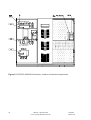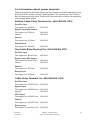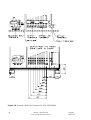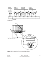
1
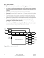
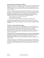
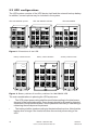
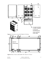
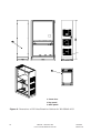
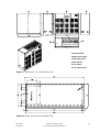
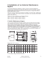
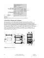
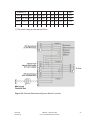
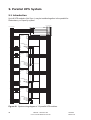
160 - 500 kVA single and
parallel UPS Systems
User’s and Installation
Manual
160kVA - 500kVA UPS User’s and Installation
Manual
1. Safety Instruction .................................................................................................. 5
2. Introduction ........................................................................................................... 7
2.1. System description .............................................................................................. 7
2.2 UPS features ......................................................................................................... 7
2.3 UPS configurations .............................................................................................. 10
3. Safety information ............................................................................................... 14
3.1 Storage and transportation ................................................................................. 14
3.2 Installation ............................................................................................................ 14
3.3 User operations ................................................................................................... 15
4. Shipping and handling ........................................................................................ 15
4.1 Unpacking and incoming inspection .................................................................. 16
4.2 Moving .................................................................................................................. 16
5. Installation ............................................................................................................ 17
5.1 Environment ......................................................................................................... 17
5.2 Floor loading ........................................................................................................ 18
5.3 Power connections .............................................................................................. 19
5.4 Information about power terminals .................................................................... 25
5.5 Mains and load connections ............................................................................... 30
5.6 Installation of Additional Optional cabinet ......................................................... 33
5.7 External Battery Cabinet Installation.................................................................. 34
6. Computer and alarm connections ...................................................................... 41
6.1 Connecting the UPS to a computer ................................................................... 42
6.2 Potential free relay outputs (TB5-TB8) .............................................................. 42
6.3 Emergency Power Off Input (EPO) (TB9) ......................................................... 43
6.4 Inputs (TB4) ......................................................................................................... 43
6.5 X-Slot Modules ..................................................................................................... 44
7. User’s guide to operations .................................................................................. 44
7.1 Graphical Control panel ...................................................................................... 45
7.2 Menu structure ..................................................................................................... 46
7.3 Manual System Control ....................................................................................... 50
7.4 Using the maintenance bypass switch .............................................................. 50
7.5 Starting up the UPS ............................................................................................. 52
7.6 Shutting down the UPS ....................................................................................... 53
8. Installation of an External Maintenance Bypass .............................................. 55
9. Parallel UPS System ............................................................................................ 58
9.1 Introduction .......................................................................................................... 58
9.2 Selecting redundancy or capacity mode .............................................................. 59
9.3 Installation requirements ..................................................................................... 59
9.4 System Startup ...................................................................................................... 64
9.5 System Shutdown .................................................................................................. 65
10. Maintenance ....................................................................................................... 66
11. Recycling the used UPS .................................................................................... 66
12. Warranty .............................................................................................................. 67
13. Technical specifications ................................................................................... 67
Copyright 2004-2005
The contents of this manual are the copyright of the
publisher and may not be reproduced (even extracts)
unless permission granted.
Every care has been taken to ensure the accuracy of
the information contained in this manual, but no liability
can be accepted for any errors or omission. The right
to make design modifications is reserved.
1 Safety Instruction
The unit must be used as intended. Follow the instructions given in the
Operating Manual.
The UPS must be installed and serviced by manufacturer, technicians or
authorized personnel only.
If necessary, only original spare parts are allowed.
See installation instructions before connecting to the supply.
Dangerous voltages are present inside the unit.
Installation and use of this equipment must comply with all national and local
regulations and procedures.
To prevent overheating, do not obstruct for ventilation grills of the unit.
The components inside the unit are not repairable by the user. The user must
not open the UPS cabinet or auxiliary cabinets or remove any protective
covers from inside the UPS cabinet.
To completely isolate the equipment, the switches IRP, IRE, IBY and IUG
must be open, the input supply and the battery supply must be isolated from
the UPS and the output isolated from other modules if the unit is part of a
multi-module system.
Capacitors inside require 5 minutes to discharge to a safe level after all
power is removed. See service manual for instructions.
High leakage current: connect protective earth before power supply cables.
Earth leakage protection: this device has a high leakage current to
protectition earth. The maximum earth leakage current is 300 mA. When
setting the threshold of the earth leakage circuit breaker installed upstream
from this equipment consider this amount of current and that due to the
loads.
An earth-fault protection device must be installed upstream, the UPS in
accordance to all applicable local regulation.
1024754
Revision A
160 kVA - 500 kVA UPS
User’s and Installation Manual
5
All primary power switches installed downstream of the UPS must be labelled
as follows: "Isolate UPS (Uninterruptible Power Supply) before working on
this circuit".
All primary power isolators installed remote from UPS require the fitting of a
waring label: "Isolate UPS (Uninterruptible Power Supply) before working on
this circuit", if the automatic beckfeed isolator is not installed.
The unit is provided with an E.P.O. (Emergency Power Off) function. This
function is activated by opening the contact at pins 1-2 of terminal TB9. This
function provides UPS disconnection from the load and from the battery (if a
shunt trip is installed in all the battery cabinets connected to the UPS and
they are connected to terminals XA1, XA3 of the UPS). Dangerous voltages
will still be present inside the unit, unless a shunt-trip for the input supply and
external battery breakers is provided. The EPO condition is reset if the
contact is closed after having opened, for this reason use a contact that
latches in the open position and that can be reset only intentionally.
During electrolysis, batteries release hydrogen gas. There is a risk of an
explosion if the amount of hydrogen in the battery room becomes too high.
Ensure appropriate ventilation of the battery room according to the standard
62040-1-1, to prevent the risk of an explosion.
Install the UPS in a temperature and humidity controlled, indoor environment.
Ambient temperature must not exceed 40°C and relative humidity 95%.
These UPSs are products for restricted sales distribution to informed
partners. Installation restrictions or additional measures may be needed to
prevent disturbances.
6
160 kVA - 500 kVA UPS
User’s and Installation Manual
1024754
Revision A
2. Introduction
This User’s manual gives basic information about 160 - 500 kVA uninterruptible
power supplies: their basic function, their features, how to use them, and what to
do in case of trouble. Instructions for shipping, storing, handling and installing the
equipment are also given.
The planning guidelines of this manual describe only the specific demands of UPS
units. Local legislation and regulations for electrical installations must be followed
in the UPS installation.
This manual is mainly intended for the chief operator/system supervisor, electrical
consultants and installation electricians.
The UPS system must be installed according to the instructions in this manual.
Fixed installation may be performed by qualified personnel only. Failure to
recognise the electrical hazards could prove fatal.
2.1. System description
A UPS (Uninterruptible Power Supply) protects different types of sensitive
electrical equipment: computers, workstations, sales terminals, critical
instrumentation, telecommunications systems, process control systems, etc. The
UPS protects them from problems associated with utility power of poor quality, or a
complete loss of power.
Sensitive electrical equipment needs protection from electrical interference.
Interference from outside the facility (such as lightning, power company accidents
and radio transmissions) and interference from inside the facility (from motors, air
conditioners, vending machines and arc welders, for example) can create
problems in the AC power line for the sensitive equipment. The problems can be:
power outage, low or high voltage, slow voltage fluctuation, frequency variations,
differential and common-mode noise, transients, etc.
The UPS cleans the utility AC power, maintains a constant voltage and if needed
isolates the output to the critical load. These actions help to keep power line
problems from reaching the critical system, where they can damage software and
hardware and cause the equipment to operate erratically.
2.2 UPS features
This UPS is a double conversion on-line UPS for protection of computer systems
and other intelligent devices such as measurement instruments and industrial
automation applications. It conditions the raw mains and supplies continuous,
clean three-phase power to the critical systems. While feeding the load the UPS
also keeps the battery constantly charged. If utility power fails, the UPS will
continue to supply clean power without any interruption at the UPS output.
If the power failure outlasts the backup time the UPS will shut down in order to
prevent a total discharge of the battery. When the line voltage is restored the UPS
will start up again automatically providing power to the critical load and charging
the battery bank.
1024754
Revision A
160 kVA - 500 kVA UPS
User’s and Installation Manual
7
UPS block diagram
An UPS module consists of several blocks each having its own functions:
•
Transients in the input and load are reduced by RFI filters.
•
AC-power is rectified and regulated in the rectifier which provides the power
to the inverter and charges the batteries. The rectifier keeps the battery fully
charged.
•
The battery provides power to the load during a mains failure.
•
The inverter converts the DC-power back to AC-power, which is delivered to
the load.
•
The static bypass switch transfers automaticly the load to the bypass line
when the inverter is overloaded or the inverter is not able to feed the load.
•
Maintenance bypass switch is used to bypass the single UPS during service.
•
The control and monitoring circuits measure, monitor and control the
operation of the UPS-system. It gives the user the status of the system
operation by visual and audible indicators.
•
The UPS sends information about the system operation via potential free
relay outputs and RS232 serial data interface This information includes data
about the utility, the load and the UPS itself. The information can be used in
a computer to ensure total protection of software and data.
Bypass
Input
Rectifier
Input
RFI
Filter
RFI
Filter
Load
Rectifier
IGBT
Inverter
Transformer
Static Bypass
Switch
Maintenance
Bypass Switch
Monitoring
Panel
Battery
RS232
CONTROL & MONITORING ABM
RFI
Filter
User
Computer
4 X-Slots
Computer
4 Relay output
Computer
4 Signal input
User
Figure 1. Block diagram of the UPS.
8
160 kVA - 500 kVA UPS
User’s and Installation Manual
1024754
Revision A
Advanced Battery Management (ABM)™
ABM monitors the status of the battery and charges it only when the battery needs
charging. This feature is very valuable since most of the time the battery does not
need charging. Hence, the function of ABM is to prolong the battery life by up to
50% on average. It also ensure that the load never looses power because of bad
or defective battery.
The key to long battery life is low corrosion inside the battery. The main cause of
corrosion is current flowing through the battery. The more current flowing through
the battery, the shorter the battery life. Current flows through the battery when it is
discharged or charged. There is very little that can be done for discharging,
because it depends on the number of power outages in the utility line. However
charging can be controlled and initiated on the following occasions:
- When turning the unit on using the on/off switch.
- After 18 days without charging
- If the open cell voltage decreases below predetermined voltage level.
Traditional UPS charge batteries continuously. This means that there is current
flowing through batteries all the time and this causes corrosion. In a traditional online UPS the inverter also causes ripple-current to be fed to the batteries, causing
corrosion.
Hot Sync™ for parallel UPS systems
A parallel UPS system means the linking together of two or more UPS units in
parallel so that in the unlikely event one fails the others can automatically take up
the load. Traditionally a parallel redundant configuration uses a common
paralleling logic circuit in the system. This logic circuit provides individual
commands to all the different units. Unfortunately this can lead to a single point of
failure for the whole system because if the logic system fails the whole UPS
system will malfunction.
That is why Hot Sync™ technology was developed. An industry leading paralleling
technology in its own right, the patented Hot Sync enables you to set up a parallel
redundant system giving you 100% conditioned power at all times. Its unique
digital design eliminates the system level single point of failure inherent in
traditional parallel UPS modules, and exponentially increases the reliability of the
overall system.
Hot Sync allows two or more UPS units to cover the same load in parallel and/or
redundant configuration, by working in complete synchronization. No common logic
is needed in this patented design. It provides automatic load sharing and module
level redundancy with nothing other than the power connecting the Hot Sync UPS
modules.
1024754
Revision A
160 kVA - 500 kVA UPS
User’s and Installation Manual
9
2.3 UPS configurations
The UPS system consists of the UPS device itself and the external backup battery.
In addition, several options may be included in the system.
UPS 160-250kVA 6 pulse
UPS 160-250kVA 12 Pulse
UPS 400-500kVA
2150
Figure 2. Dimensions of the UPS.
Battery Cabinet BCPWS
Battery Cabinet BCPWD
Auxiliary Cabinet ACPW
Figure 3. Battery cabinets & auxiliary cabinets for 160-250kVA UPS
The main considerations in planning the UPS system are:
•
The UPS output power rating shall be specified according to the total power
demand of the protected system. Some margin should be allowed for potential
expansion of the protected system, and for possible inaccuracy in calculating or
measuring the actual power requirement.
•
The battery shall be sized according to the desired backup time. Note that the
backup time is longer if the load is less than the nominal power rating of the
UPS.
10
160 kVA - 500 kVA UPS
User’s and Installation Manual
1024754
Revision A
1 Large front Panel
2 Small front panel
3 Side panel
4 Front top panel
5 Rear top panel
Figure 4. Dimensions of the 160-250kVA UPS 6Pulse.
6 Rear Panel
Optional
12 Pulse only
g
Figure 5. Base Plant for 160-250kVA UPS 6 Pulse & 12 Pulse.
1024754
Revision A
160 kVA - 500 kVA UPS
User’s and Installation Manual
11
1 Front door
2 Top panel
3 Rear panel
Figure 6. Dimensions of 12 Pulse Extention Cabinet for 160-250kVA UPS.
12
160 kVA - 500 kVA UPS
User’s and Installation Manual
1024754
Revision A
1 Front panels
2 Right side panel
3 Left side panel
4 Rear panel
5 Top panel
6 Top cable entry
Figure 7. Dimensions of 400-500kVA UPS.
Figure 8. Base Plant for 400-500kVA UPS
1024754
Revision A
160 kVA - 500 kVA UPS
User’s and Installation Manual
13
Options
The options are used to tailor the solution to the site and load requirements of the
installation.
The following options are available:
•
External battery cabinets
•
External bypass isolation transformers
•
12 Pulse Rectifier without galvanic isolation (standard for 400-500kVA UPS)
•
12 Pulse rectifier and XI & XIII harmonic THD filter
•
External Maintenance Bypass (2 switches)
•
External Maintenance Bypass (3 switches)
•
External Battery Breakers
•
Remote and multilingual ViewUPS display panel
•
RS-232 communication adapter (xslot)
•
SNMP/Web communication adapter (ConnectUPS)
•
AS/400 relay adapter (xslot)
•
Modem board (xslot)
•
Modbus/Jbus communication adapter (xslot)
•
Top cable entry (standard for 400-500kVA UPS)
•
Backfeed protection
•
ABM
3. Safety information
Since the UPS system operates on line power and contains a bank of high-current
backup batteries, the information in this chapter is important to all personnel
involved.
3.1 Storage and transportation
Because of the heavy weight of the cabinets and the high energy battery bank the
equipment must be handled with care. The UPS must always be kept in the
position marked on the package and must not be dropped.
3.2 Installation
Do not operate the equipment in the presence of flammable gases or fumes.
Operation of any electrical equipment in such an environment constitutes a safety
hazard. Do not place the UPS in an airtight room.
The UPS system must be installed according to the instructions in this manual.
Installation may be performed by qualified personnel only. Failure to recognise the
electrical hazards could prove fatal.
14
160 kVA - 500 kVA UPS
User’s and Installation Manual
1024754
Revision A
WARNING!
Do not open the UPS or battery cabinet. Some components inside the
cabinets carry high voltages. To touch them may prove fatal. All
operations inside the cabinets must be carried out only by a service
engineer from the manufacturer or from an agent authorised by the
manufacturer.
3.3 User operations
The only user operations permitted are:
•
Starting up and shutting down the UPS unit (not the initial start up).
•
Operating the user interface.
•
Connecting data interface cables.
•
Monitoring the UPS with the software provided.
These operations must be performed according to the instructions in this manual.
During any of these operations, the user must take greatest care, and perform only
the prescribed operations. Any deviation from the instructions could be dangerous to
the operator.
4. Shipping and handling
The UPS equipment is shipped on specifically designed pallets so that it is easy to
move with a forklift or pallet jack.
Do not stack the pallets.
Because of the sensitive electronics and high energy stored within batteries, the
UPS and the battery cabinet must be handled with care. The UPS and battery
cabinet must always be kept in an upright position and must not be dropped.
Because of the heavy weight of the UPS system proper provision must be made
for transportation. See technical specifications for dimensions and weights of the
UPS.
If the UPS is not immediately installed the following must be remembered:
•
The UPS should be stored in the original packing and shipping carton.
•
The recommended storing temperature is between +15°C ... +25°C.
•
The equipment must always be protected from dust, moisture and weather.
If the UPS is stored for a long period of time, the batteries of the UPS should be
charged for at least 8 hours every 6 months to maintain the battery condition.
1024754
Revision A
160 kVA - 500 kVA UPS
User’s and Installation Manual
15
4.1 Unpacking and incoming inspection
Unpack the equipment and remove all the packing materials and shipping cartons.
•
The equipment must be inspected for damage after shipment. If damage has
occurred during transit, all the shipping cartons and packing materials should be
stored for further investigation. If the damage is visible a claim for shipping
damage must be filed immediately. Note: Check the shock/tilt indicator.
To file a claim for shipping damage:
•
The carrier must be informed within 7 days of receipt of the equipment.
Remove the equipment from the pallet according to figure 9.
The equipment must be checked against the packing list to verify that the shipment is
complete.
UPS 160-250kVA
UPS 400-500kVA
Figure 9. Removing the UPS from a pallet.
Note: The 400-500 kVA UPS should be be forked from the rear side where the
unit is heavier, it can be also forked from the right side if a long fork is used.
The UPS is thoroughly inspected at the factory. If there is no damage or
discrepancies, the installation may proceed.
4.2 Moving
The UPS units can be moved with fork lift or pallet jack. Because the UPS is
heavy, it should be verified that surfaces on which it is moved are strong enough.
16
160 kVA - 500 kVA UPS
User’s and Installation Manual
1024754
Revision A
5. Installation
The UPS unit is designed with all vital parts accessible from front. All cables and
protective fuses must be dimensioned according to local regulations.
5.1 Environment
All the requirements concerning environment described in this chapter
(Installation) or “Technical specifications” chapter must be met. If they
are neglected the manufacturer cannot guarantee the safety of personnel
during installation or use, or that the unit will function properly.
When locating the UPS system and the battery options, the following points have
to be remembered:
•
Avoid temperature and humidity extremes. To maximise the life time of the
batteries, an ambient temperature of 15°C to 25°C is recommended.
•
Provide shelter from the elements (especially moisture)
•
The UPS can be mounted against the wall. No space is required at rear or
sides of the UPS. Always leave 500 mm free space above the UPS. Always
leave enough space in front of the UPS (minimum 1 meter) for service and
maintenance. See figure 10.
•
The batteries should preferably be installed next to the UPS. The right side is
recommended due to the power cable fastening, an opening is provided on the
right panel of the UPS and on the left panel of the battery cabinet for cabling
(see “External Battery Cabinet Installation” chapter).
9370
Figure 10. Ventilation and space requirements for 160 - 500 kVA UPS.
1024754
Revision A
160 kVA - 500 kVA UPS
User’s and Installation Manual
17
5.2 Floor loading
When planning the installation the floor loading must be taken into consideration
because of the heavy weight of the UPS and battery cabinets.
The strength of the installation surface must be adequate for point and distributed
loadings given in table 1.
Description
Weight
(kg)
Point loading
(kg/cm2)
Distributed
loading
(kg/m2)
Dimensions
WxDxH
160-250 kVA UPS 6 Pulse
1130
1,8
1077
1220x860x1900
160-250 kVA UPS 12 Pulse
1820
1,4
1306
1620x860x1900
160-250 kVA UPS 12 Pulse & THD Filter
1910
1,5
1370
1620x860x1900
400-500 kVA UPS
2880
1,2
1564
2150x860x1900
THD Filter (for 400-500 kVA UPS)
390
-
-
-
ABM 160-250 kVA UPS option
15
-
-
-
ABM 400-500 kVA UPS option
16
-
-
-
Top cable entry option for 160-250 VA UPS 35
-
-
-
BCPWS Battery cabinet (*)
210 (*)
(**)
(***)
818x860x1900
BCPWD Battery cabinet (*)
410 (*)
(**)
(***)
1596x860x1900
Table 1. The UPS floor loading of UPS modules and external options.
(*) The weight is referred to the empty cabinet: add the weight of the battery.
(**) To calculate point loading (kg/cm2) add the weight of the cabinet to the weight
of the batteries and divide by 640 for BCPWS and 1280 for BCPWD.
(***) To calculate distributed loading (kg/m2) add the weight of the cabinet to the
weight of the batteries and divide by 0.7 for BCPWS and 1.4 for BCPWD.
18
160 kVA - 500 kVA UPS
User’s and Installation Manual
1024754
Revision A
5.3 Power connections
The electrical planning and the UPS installation must be done by qualified personnel
only. All power connections shall be done with cable lugs.
WARNING!
The UPS contains high voltage and current which can injure or kill personnel
and damage equipment.
The customer has to supply the wiring to connect the UPS to power lines.
The installation inspection and initial start up of the UPS and extra battery cabinet
must be carried out by a service engineer from the manufacturer or from an agent
authorised by the manufacturer.
The UPS unit has the following power connections:
•
3-phase and PE connection for rectifier input
•
3-phase and N and PE connection for bypass input
•
3-phase and N and PE connection for load output
•
+, - and PE connection for batteries
Note: PE connection is provided on a copper ground bar
All input and output wiring of the UPS connects to the terminals located behind the
cover plates behind the doors.
The UPS is provided with a single phase L-N power outlet protected with a 10A
fuse.
1024754
Revision A
160 kVA - 500 kVA UPS
User’s and Installation Manual
19
Figure 11. UPS 160-250kVA std 6 Pulse - location of electrical components.
20
160 kVA - 500 kVA UPS
User’s and Installation Manual
1024754
Revision A
Figure 12. UPS 160-250kVA 6 Pulse (full features) - Location of electrical
components.
1024754
Revision A
160 kVA - 500 kVA UPS
User’s and Installation Manual
21
THD Filters
Figure 13. UPS 160-250kVA 12 Pulse & THD optional Filters
Intelligent THDI reduction and PF improvement. The load is continuosly monitored
with filter disconnection if load is <25% and overcurrent protection.
22
160 kVA - 500 kVA UPS
User’s and Installation Manual
1024754
Revision A
Figure 14. UPS 400-500kVA std - location of electrical components.
1024754
Revision A
160 kVA - 500 kVA UPS
User’s and Installation Manual
23
Figure 15. UPS 400-500kVA full features - location of electrical components.
24
160 kVA - 500 kVA UPS
User’s and Installation Manual
1024754
Revision A
5.4 Information about power terminals
Fastening torques for terminals depend on type of cable shoes and materials. If using
aluminium shoes, please use anti-oxydizing paste in the connections. The UPS has
bolts for the power connections. Please check the local safety rules for the installation
when designing the cables:
Bottom Cable Entry Terminal for 160-250kVA UPS:
Rectifier input
Flat copper bar 40*5mm
Bolt M12
Bypass input/UPS Output
Flat copper bar 30*8mm
Neutral
Bolt M12
Bolt M12
Ground
Flat copper bar 40*5mm
Bolt M12
Battery Input
Flat copper bar 40*8mm
Bolt M12
Top Cable Entry Terminal for 160-250kVA UPS:
Rectifier input
Flat copper bar 80x40*5mm
Bolt M12
Bypass input/UPS Output
Flat copper bar 80x40*5mm
Neutral
Bolt M12
Bolt M12
Ground
Flat copper bar 50*8mm
Bolt M12
Battery Input
Flat copper bar 50*8mm
Bolt M12
Cable Entry Terminal for 400-500kVA UPS:
Rectifier input
Flat copper bar 255x80*6mm
Bolt M12
Bypass input
Flat copper bar 255x80*6mm
Neutral
Bolt M12
Bolt M12
UPS Output
Flat copper bar 400x80*6mm
Bolt M12
Ground
Flat copper bar 100x80*6mm
Bolt M12
Battery Input
Flat copper bar 40*8mm (x2)
1024754
Revision A
Bolt M12
160 kVA - 500 kVA UPS
User’s and Installation Manual
25
Figure 16. Bottom Cable Entry Terminal for UPS 160-250kVA
26
160 kVA - 500 kVA UPS
User’s and Installation Manual
1024754
Revision A
BATTERY
TERMINALS
B+
B-
RECTIFIER
INPUT
TERMINALS
1L1
1L2
1L3
OUTPUT
TERMINALS
BYPASS LINE
TERMINALS
4-N
4-L3 4-L2
4-L1
5-N
5-L3
5-L2 5-L1
GROUND
REAR VIEW
Figure 17. Top Cable Entry Terminal for UPS 160-250kVA
1024754
Revision A
160 kVA - 500 kVA UPS
User’s and Installation Manual
27
Figure 18. Cable Entry Terminals for UPS 400-500kVA STD
28
160 kVA - 500 kVA UPS
User’s and Installation Manual
1024754
Revision A
Figure 19. Cable Entry Terminals for UPS 400-500kVA full features
1024754
Revision A
160 kVA - 500 kVA UPS
User’s and Installation Manual
29
5.5 Mains and load connections
The proper connection order is as follows:
1.
Switch off the supply to the distribution point to which the UPS unit is to be
connected.
2.
For extra safety, also remove the fuses from the selected lines.
Make absolutely sure with measurement that there is no power.
3.
A readily accessible disconnect device must be incorporated in all fixed input
wiring. The disconnect device shall have a contact separation of at least 3
mm.
4.
Check that electrical connections to the installation site have been properly
executed. Also check fuse or circuit breaker ratings and cable dimensions
against tables 2or 3for 160-500 kVA systems.
5.
The UPS should be connected in accordance with figures 20 and 21.
6.
If singlefeed installation is required, the interconnection cables between the 2
inputs must be provided by the customer.
7.
Connect input cables and output cables to the UPS.
Neutral is requested on the bypass input.
8.
Make sure that the UPS unit output cable is connected to the load.
9.
Connect the battery to the UPS: power cables to terminals +B, -B. Connect
C1,C2 (n.o auxiliary contact) to terminals XA5, XA4 and C3,C4 (shunt trip) to
XA1, XA3. If multiple battery cabinets are used connect the power cables in
parallel to +B,-B, all shunt trip coils in parallel to XA1, XA3 and connect in
parallel the auxiliary contacts.
10. Also connect any computer and alarm connections according to chapter 6.
These connections are in the user interface area behind the right-hand door.
11.
If an external bypass switch will be used, contact your dealer first.
Note: If the battery breaker is not equipped with an auxiliary contact, monitoring of
the switch status can be disabled via Service Software.
With shielded power cables, the 9370-500 complies with the limits given in table 3 of
EN50091-2. Installation instructions must be issued in order to ensure proper shielding of the power cables in the field: “in order to comply with all the EMC requirements
and in particular with the radiated emission limits in accordance to EN50091-2, all
power cables must be installed with adequate earthed shield”.
The UPS unit is now connected to the mains and to the load but there is no power.
Make sure that the connections are properly made.
30
160 kVA - 500 kVA UPS
User’s and Installation Manual
1024754
Revision A
L1
L2
L3
N
PE
1
A
N
B
2
IRE(*2)
IRP
BCPW
C1
XA.5
XA.4
C2
+B
-B
+B
-B
XA.1
XA.3
C4
~
=
D
C3
IB
ABM (*1)
IBY
=
~
BCPW
C1
C2
+B
-B
IB
D
C3
C4
IUG
C
N
L1
L2
L3
N
(*1)=ABM Optional
(*2)=IRE is an on load isolator, or backfeed contactor as an option
Figure 20. Interconnection of 6 Pulse UPS 160-250 kVA
Power
Fuse 1
Fuse 2
Cable A
Cable B
Cable N
160 kVA
20 0 kVA
250 kVA
40 0 A
40 0 A
630 A
40 0 A
40 0 A
630 A
3x2x95 mm²
3x2x120 mm²
3x2x150 mm²
3x2x95 mm²
3x2x120 mm²
3x2x150 mm²
1x2x95 mm²
1x2x120 mm²
1x2x185 mm²
Cable C
3x2x95 mm²
3x2x120 mm²
3x2x150 mm²
Cable D
2x2x120 mm²
2x2x185 mm²
2x2x120 mm²
Table 2. Fuse and cable dimensions for installations of UPS units from 160 to 250
kVA. Note that the fuse numbers and the cable letters refer to the numbers/letters in
figure 20. Slow gG/gL fuses should be used to protect cables.
Note: Cable size is for indication only. The cross section (including the PE cable) will
depend on insulation temperature rating, cable lenght and local regulations.
Please note that the battery cables delivered with the external battery cabinets are to
install the external battery cabinet to the right side of the UPS.
1024754
Revision A
160 kVA - 500 kVA UPS
User’s and Installation Manual
31
(*1)=ABM Optional
(*2)=IRE is an on load isolator, or backfeed contactor as an option
Figure 21. Interconnection of 12 Pulse UPS.
Power
Fuse 1
Fuse 2
Cable A
Cable B
Cable N
160 kVA
20 0 kVA
250 kVA
40 0 kVA
50 0 kVA
40 0 A
40 0 A
630 A
80 0 A
10 0 0 A
40 0 A
40 0 A
630 A
80 0 A
10 0 0 A
3x2x95 mm²
3x2x120 mm²
3x2x150 mm²
3x2x30 0 mm²
3x3x240 mm²
3x2x95 mm²
3x2x120 mm²
3x2x150 mm²
3x2x240 mm²
3x3x185 mm²
1x2x95 mm²
1x2x120 mm²
1x2x185 mm²
1x3x240 mm²
1x4x185 mm²
Cable C
3x2x95 mm²
3x2x120 mm²
3x2x150 mm²
3x2x240 mm²
3x3x185 mm²
Cable D
2x2x120 mm²
2x2x185 mm²
2x2x120 mm²
2x3x240 mm²
2x3x30 0 mm²
Table 3. Fuse and cable dimensions for five wire installations of UPS units from 160
to 500 kVA. Note that the fuse numbers and the cable letters refer to the numbers/
letters in figure 21. Slow gG/gL fuses should be used to protect cables.
Note: Cable size is for indication only. The cross section (including the PE cable) will
depend on insulation temperature rating, cable lenght and local regulations.
Please note that the battery cables delivered with the external battery cabinets are to
install the external battery cabinet to the right size of the UPS.
32
160 kVA - 500 kVA UPS
User’s and Installation Manual
1024754
Revision A
5.6 Installation of Additional Optional cabinet
L1
L2
L3
N
PE
1
A
2
B
RST
ACPW
(*4)
Y
UVWN
IRE(*2)
IRP
BCPW
IB
XA.5
XA.4
C1
C2
+B
ABM (*1)
=
D
-B
C3
C4
~
(*3)
XA.1
XA.3
IBY
=
~
IUG
N
C
L1
L2
L3
N
Note: (*1)=ABM Optional; (*2)=IRE is an on load isolator, or backfeed contactor as
an option; (*3)= Built in inverter transformer; (*4)= The rating of the isolation
transformer is limited to 100% of the UPS size
Figure 22. Interc.of UPS with bypass input transformer for input/output isolation.
Power
Fuse 1
Fuse 2
Cable A
Cable B
Cable N
160 kVA
20 0 kVA
250 kVA
40 0 kVA
50 0 kVA
40 0 A
40 0 A
630 A
80 0 A
10 0 0 A
310 A
310 A
40 0 A
3x2x95 mm²
3x2x120 mm²
3x2x150 mm²
3x2x30 0 mm²
3x3x240 mm²
3x2x95 mm²
3x2x120 mm²
3x2x150 mm²
3x2x240 mm²
3x3x185 mm²
1x2x95 mm²
1x2x120 mm²
1x2x185 mm²
1x3x240 mm²
1x4x185 mm²
Cable C
3x2x95 mm²
3x2x120 mm²
3x2x150 mm²
3x2x240 mm²
3x3x185 mm²
Cable D
2x2x120 mm²
2x2x185 mm²
2x2x120 mm²
2x3x240 mm²
2x3x30 0 mm²
Tab.4. Fuse and cable dimensions for installations of UPS units from 160 to 500 kVA.
1024754
Revision A
160 kVA - 500 kVA UPS
User’s and Installation Manual
33
5.7 External Battery Cabinet Installation
The batteries should preferably be installed next to the UPS. The right side is
recommended due to the power cable fastening, an opening is provided on the right
panel of the UPS and on the left panel of the battery cabinet for cabling.
Battery Cabinet 1 Battery Cabinet 2
UPS
Top cable entry optional
Top cable entry optional
Cable entries UPS
Cable entries Battery Cabinet
Battery Cabinet 1
Battery Cabinet 2
C3
C4
-B
+B
C1
C2
C3
C4
-B
+B
C1
IB
XA.4
XA.5
-B
+B
XA.3
XA.1
C2
IB
Figure 23. Interconnection of Battery cabinets
34
160 kVA - 500 kVA UPS
User’s and Installation Manual
1024754
Revision A
BCPWS 1x32/400 Battery Cabinet (32 Monoblocks 12V)
Dimensions:
Height 1900 mm
Width 818 mm
Depth 860 mm
To assemble the battery cabinet:
IMPORTANT: Open the IB battery switch before connecting the cables.
•
Remove the screws that fix the trays.
•
Extract the trays of the battery cabinet.
•
Place eight battery blocks on the trays of the first, second, third and fourth
level.
•
Interconnect the blocks in series (block 1 / negative pole ==> block 2 / positive
pole, according to the diagram on next page).
BCPWS 12V Bottom Cable Entry
BCPWS 12V Top Cable Entry
1
2
+1
1
2
4
-5
3
2
2
3
3
4
4
3
3
4
2
3
4
-5
4
+1
2
Figure 24. BCPWS 1x32/400 12V Battery layout - bottom & top cable entry
1024754
Revision A
160 kVA - 500 kVA UPS
User’s and Installation Manual
35
WARNING: after assembly there is a voltage of 96V on each level.
•
•
Insert the trays and fix them with the screws.
Connect the battery blocks of the various levels to IB, and connect IB to the
relevant UPS terminals, as shown in figure 25.
Ensure appropriate ventilation of the battery room according to the standard
62040-1-1, to prevent the risk of an explosion.
Figure 25. BCPWS 1x32/400 12V bottom cable entry electrical connections
Figure 26. BCPWS 1x32/400 12V top cable entry electrical connections
36
160 kVA - 500 kVA UPS
User’s and Installation Manual
1024754
Revision A
BCPWD/400 & BCPWD/630 Battery Cabinet
(64 Monoblocks 6V)
Dimensions:
Height 1900 mm
Width 1596 mm
Depth 860 mm
To assemble the battery cabinet:
IMPORTANT: Open the IB battery switch before connecting the cables.
•
Remove the screws that fix the trays.
•
Extract the trays of the battery cabinet.
•
Place eight battery blocks on the left and right trays of the first, second, third
and fourth level.
•
Interconnect the blocks in series (block 1 / negative pole ==> block 2 / positive
pole, according to the diagram on next page).
WARNING: The nominal voltage of the monoblocks must be 6V (in fact
64x6=384V (nominal voltage)
BCPWD 6V Bottom Cable Entry
BCPWD 6V Top Cable Entry
1
1
+1D
2S
2D
+1S
1
2
2
1
4S
-5S
3S
-5D
4D
2S
3D
2D
2
3
2
3
3D
4D
4D
3S
3D
4S
4S
3S
3
4
4
3
2S
3S
4S
2D
-5S
3D
-5D
4D
4
4
+1S
+1D
2D
2S
Figure 27. BCPWD/400 & BCPWD/630 6V bottom & top cable entry - battery layout
1024754
Revision A
160 kVA - 500 kVA UPS
User’s and Installation Manual
37
WARNING: after assembly there is a voltage of 48V on each level of left and
right tiers.
•
•
Insert the trays into the battery cabinet and fix them with the screws.
Connect the battery blocks of the various levels to IB, and connect IB to the
relevant UPS terminals, as shown in fig. 28.
Ensure appropriate ventilation of the battery room according to the standard
62040-1-1, to prevent the risk of an explosion.
Figure 28. BCPWD/400 & BCPWD/630 6V bottom cable entry elect. connections
Figure 29. BCPWD/400 & BCPWD/630 6V bottom cable entry elect. connections
38
160 kVA - 500 kVA UPS
User’s and Installation Manual
1024754
Revision A
BCPWD-2x32/400 & BCPWD-2x32/630
Battery Cabinet (64 Monobloks 2x32 12V)
Dimensions:
Height 1900 mm
Width 1596 mm
Depth 860 mm
To assemble the battery cabinet:
•
•
•
•
IMPORTANT: Open the IB battery switch before connecting the cables.
Remove the screws that fix the trays.
Extract the trays of the battery cabinet.
Place eight battery blocks on the left and right trays of the first, second, third
and fourth level.
Interconnect the blocks in series (block 1 / negative pole ==> block 2 / positive
pole, according to the diagram on next page).
WARNING: The nominal voltage of the monoblocks must be 12V (in fact
32x12=384V (nominal voltage)
BCPWD 12V Bottom Cable Entry
BCPWD 2V Top Cable Entry
Figure 30. BCPWD/400 & BCPWD/630 2X32 12V bottom & top cable entry - battery
layout
1024754
Revision A
160 kVA - 500 kVA UPS
User’s and Installation Manual
39
Warning: after assembly there is a voltage of 96V on each level of the left and
right tiers.
•
Insert the trays into the battery cabinet and fix them with the screws.
•
Connect the battery blocks of the various levels to the IB battery switch, and
the IB to the terminals, as shown in fig. 31.
Ensure appropriate ventilation of the battery room according to the standard
62040-1-1, to prevent the risk of an explosion.
FIG. 31 BCPWD/400 & BCPWD/630 2X32 12V bottom cable entry electrical
connections
FIG. 32 BCPWD/400 & BCPWD/630 2X32 12V top cable entry electrical
connections
40
160 kVA - 500 kVA UPS
User’s and Installation Manual
1024754
Revision A
6. Computer and alarm connections
An interface for direct communication with your computer system is supplied in the
UPS unit. The interface consists of RS232 serial data interface, four optional X-slots,
four potential free relays and four programmable inputs for building alarms. These
interfaces are located behind the right-hand door.
Figure 33. The user interface area
Note!
All connections mentioned in chapter 6 must not be galvanically connected
to any mains connected circuits. Reinforced insulation to the mains is
required.
The routing of the cables shall be done separate from any power cables
1024754
Revision A
160 kVA - 500 kVA UPS
User’s and Installation Manual
41
6.1 Connecting the UPS to a computer
The UPS is delivered as a complete solution package with accompanying Software
Suite. To connect the UPS to the computer, use the communication cable provided
with the package. (Note: If using other cable, verify the pin configuration from Table 5.)
Check from the software documentation that the platform running on your computer is
supported. Follow the instructions of the Software Suite to choose and complete the
required software installation. For other operating systems, SNMP and more
advanced power protection solution combinations, please contact your local dealer.
RS232 serial data interfaces
The RS232 interface J18 uses 9-pin female D-sub connector. The information
includes data about the utility, load and the UPS itself. The connector J18 is to be
used with a computer connection or a modem connection. See below the meaning
of the pins. The RS232 must not be galvanically connected to any mains
connected circuits. Reinforced insulation to the mains is required.
The baud rate can be configured for 1200/2400/9600/19200 bps from the LCD
display. For appropriate baud setting refer to software manuals. The serial port has
the following format:
• Data bits
8
• Parity
None
• Stop bits
1
• Handshake
None
Pin #
Signal name
Direction from the UPS
Description
2
3
5
9
RxD
TxD
GND
+V
Out
In
–
Out
Received data
Transmitted data
Signal ground
Power source 8 to 12 volts DC
Table 5. RS232 connection (J18) for the computer, 9-pin female D-sub.
6.2 Potential free relay outputs (TB5-TB8)
This relay interface consists of four potential free relays providing complete isolation
between the UPS and the computer. The Relay 1 and Relay 2 are not used at the
moment. The function for Relay 3 is “System on battery”. The function for Relay 4 is
“UPS on/ok”. In figure 34 the relay is shown as de-energized.
3 NC
2 NO
1 COM
Figure 34. Programable output relay configuration. All potential free contacts.
Note! The relay contacts are rated for maximum 8 A/240 Vac or 5A/30 Vdc
resistive load. All relay outputs are galvanically isolated from the other circuits of
the UPS (IEC 60950, EN 620401-1). The relay contacts must not be galvanically
connected to any mains connected circuits. Reinforced insulation to the mains is
required.
42
160 kVA - 500 kVA UPS
User’s and Installation Manual
1024754
Revision A
6.3 Emergency Power Off Input (EPO) (TB9)
This input is used to shut down the UPS from a distance. This feature can be used for
emergency power down, or for shutting down the load and the UPS by thermal relay,
for instance in the event of room overtemperature. Remote shut down wires are
connected to terminal block TB9 pins 1 and 2, (see figure 33).
The EPO terminals have been connected together at the factory. When this connection is
open, the logic hard wire circuitry will immediately shut down the UPS, thus preventing the
UPS from supplying the load. In order to have the UPS running again the EPO pins have
to be connected and the UPS restarts. The pins must be shorted in order to keep the
UPS running. Maximum resistance is 10 ohm. The EPO must not be galvanically
connected to any mains connected circuits. Reinforced insulation to the mains is
required.
The EPO condition is reset if the contact is closed after having opened, for
this reason use a contact that latches in the open position and that can be
reset only intentionally.
6.4 Inputs (TB4)
The UPS communication device includes four inputs (terminal block 4: 1-2, 3-4, 56, 7-8) for building alarms. These inputs can be used for example on Generator
signal, shutting down and starting up inverter remotely or switching to bypass
mode remotely. These inputs can be activated by connecting the two pins
together of the particular terminal.
These inputs have the following values:
Generator On Input TB4:1,2
The Generator On input is used for inhibiting the transfer to static bypass line
when the UPS is supplied by an unstable ac source.
The generator auxiliary contact wires are connected on terminal block 4: 1,2 (see
figure 33). In normal operations the terminals 1 and 2 are not connected together.
When these pins are connected together by floating contacts of the generator
control device, the logic circuitry in the UPS will prevent the transfer to an unstable
power source. When the unit is delivered the connection on terminals 1 and 2 will
be open.
Remote Output On/Off Input TB4: 3, 4
The Remote Output On/Off input is used to turn off the output of the UPS from a
distance. Remote Output On/Off wires are connected on terminals 3 and 4 (see
figure 33).
The terminals 3 and 4 are not connected together in normal operation. When the pins
are connected together by floating contact the inverter will be turned off and also the
static bypass line will be turned off. In order to turn on the inverter and the static bypass
line the connection between these pins has to be opened.
External Bypass Switch Input TB4: 5, 6
1024754
Revision A
160 kVA - 500 kVA UPS
User’s and Installation Manual
43
If the UPS system is equipped with an external bypass switch, its status can be monitored
by the UPS via terminals 5 and 6. The external bypass switch auxiliary contact wires are
connected on terminals 5 and 6 (see figure 33). For normal UPS operation the
connection shall be open as default. If an external bypass switch will be used, contact
your dealer first.
Environment Alarm Input TB4: 7, 8
The environment alarm input is used for connecting the UPS to your building alarms,
such as overtemperature or smoke detector alarms.
The environment alarm input contact wires are connected on terminals 7 and 8 (see
figure 33). When this alarm is activated it will be indicated to the user through RS232
ports. When connection on terminals 7,8 is open, the alarm is inactive as default.
Note!
The programmable auxiliary inputs (Generator ON, External Bypass Switch, Remote
Output On/Off, Environment Alarm) must not be galvanically connected to any mains
connected circuits. Reinforced insulation to the mains is required for equipments and
cables connected to these connections.
Note!
The programmable auxiliary inputs are NOT galvanically isolated from each other.
Use dry contacts.
WARNING: If the contacts must be connected to more than one input of the
same board or to input of more than one unit, it’s mandatory to respect the
polarity.
6.5 X-Slot Modules
Optional X-Slot modules allow the UPS to communicate in a variety of networking
environments and with different types of devices. The UPS is compatible with any
X-slot module, including:
•
RS232 Module - has one serial communication port.
•
Modbus/Jbus Module - connects to an industrial automation system
•
AS400 Relay Module - provides additional relay outputs
•
SNMP/Web Module - has a flexible SNMP/Web communication port.
•
Modem Module - provides modem functions for remote monitoring
44
160 kVA - 500 kVA UPS
User’s and Installation Manual
1024754
Revision A
7. User’s guide to operations
This chapter contains the necessary information on how to use the UPS.
The control panel provided to the user UPS status, measurements, alarms and
history log. It is also used to control and configure the UPS with the function buttons
underneath the display.
During commissioning the manufacturer representative will train the users to operate
the UPS system.
7.1 Graphical Control panel
The monitor panel shows the status of UPS operation with five LED indicators and with
a LCD screen. The display also generates audible alarm if the user should be alerted.
Figure 35. Control panel with the main screen
LED indicators
This green LED is lit when there is voltage at the output terminals and
when the UPS is in normal or static bypass mode.
This yellow LED is lit when the UPS is operating in battery mode.
This yellow LED is lit when UPS is on and is operating in bypass mode.
This yellow LED is lit when there is an active notice that does not
require immediate action.
This red LED is lit when there is an active alarm that requires
immediate action.
There are five pushbuttons underneath the LCD display that are used to access
the menu structure.
1024754
Revision A
160 kVA - 500 kVA UPS
User’s and Installation Manual
45
7.2 Menu structure
The UPS main menu allows you to display data in the information area to help you
monitor and control UPS operation. The following menus and options are
available:
Events
Displays the list of Active Events and a historical log of system events.
Meters
Displays performance meters for the system or critical load.
Setup
Allows one to view contrast, date & time, firmware versions,
system identity and parallel information. Configuration of the UPS
requires a password. The password for changing defaults is USER.
↵
Returns to Main Menu and displays a real-time graphic representation
of the power flow through the internal UPS components.
You can access the above mentioned menus by pressing the function button
underneath the respective menu.
To scroll through the menu selections use ↑ or ↓ pushbuttons from the display
menu.
Events
Active Events
History
Meters
Input
U12 U23 U31
Freq
Output
L-N
UL1 UL2 UL3 kVA kW PF
IL1 IL2 IL3 Freq
L-L
U12 U23 U31 kVA kW PF
IL1 IL2 IL3 Freq
Bypass
U12 U23 U31 Freq
UL1 UL2 UL3
Battery
U=
I=
Backup time:
<ABM status>
Output load
125%
100%
75%
50%
25%
0%
L1 L2 L3
46
160 kVA - 500 kVA UPS
User’s and Installation Manual
1024754
Revision A
*= default factory setting
1024754
Revision A
160 kVA - 500 kVA UPS
User’s and Installation Manual
47
Disable input filter
Filter disabled/not installed
Filter disabled on sig in 1--Filter disabled on sig in -2-Filter disabled on sig in --3Filter disabled on sig in ---4
Filter disabled on sig in 12-Filter disabled on sig in -23Filter disabled on sig in --34
Filter disabled on sig in 1-3Filter disabled on sig in 1--4
Filter disabled on sig in -2-4
Filter disabled on sig in -234
Filter disabled on sig in 1-34
Filter disabled on sig in 12-4
Filter disabled on sig in 123Filter disabled on sig in 1234
Filter Enabled
Reset all parameters
Batteries
Show cabinet info
Install new cabinet
Remove cabinet
Battery capacity
Signal Inputs
48
TB4 1-2
Generator On Signal
TB4 3-4
Remote Shutdown Signal
TB4 5-6
External Bypass Switch Signal
TB4 7-8
Environment Alarm 1...8
160 kVA - 500 kVA UPS
User’s and Installation Manual
1024754
Revision A
Relays
On-board TB8
System on battery
On-board TB7
Battery low
UPS On/Ok
UPS on bypass
SLOT1...4 Relay K 1...4
Alarm
Custom 1...8
Alarms
Alarms Configuration:
Total of 191 alarms (service)
Contrast
0...100%
Date & Time
DAY DT MONTH YEAR HOUR
MINUTE SAVE
Serial Ports
SLOT 1...4
Speed
300
1200
RS232
2400
4800
9600 (*)
19200
Modem
None (*)
Generic
XCP
Enabled (*)
Disabled
UPS code
Enabled (*)
Disabled
Control Commands
Enabled
Disabled (*)
1024754
Revision A
160 kVA - 500 kVA UPS
User’s and Installation Manual
49
7.3 Manual System Control
The System Controls screen appears when the
pushbutton is pressed.
The transfer to bypass and back to normal mode are controlled from this screen by
pressing the Bypass and Normal pushbuttons. As a safety feature the UPS can be
locked to bypass mode via software and an alarm will be given. To return to normal
operation press Reset and UPS will transfer to normal operation. These operations
are controlled by the UPS firmware and allowed if the conditions for transfer are
acceptable.
Pushbuttons
This button is for accessing the language selection menu (future)
This button is used to access the manual system control menu:
RESET - BYPASS - NORMAL
This button is used to acknowledge the alarms and silence the horn.
7.4 Using the maintenance bypass switch
The UPS unit is provided with an internal maintenance bypass switch. This switch is
used to bypass the UPS during maintenance or servicing.
Maintenance bypass switch is located behind the left door.
The maintenance bypass switch has the following positions:
OPEN (UPS)- normal position, inverter/static switch is supplying power to the load.
CLOSED (BYPASS)- the UPS is mechanically bypassed and the load is supplied
from the bypass input power line. This position allows testing of the UPS
without disturbing the load. When the UPS is turned off and the maintenance
bypass switch is closed and IRP, IRE, IUG are opened, the UPS is isolated from
the input and output power lines. Open the switch in the battery cabinets to
isolate the UPS from the battery.
50
160 kVA - 500 kVA UPS
User’s and Installation Manual
1024754
Revision A
WARNING!
Dangerous voltages are still present on the switch terminals during the
bypass operation.
Note!
Maintenance bypass switch is used only on rare occasions. If the bypass
input frequency or voltage is not correct and the UPS is not synchronized to
mains or static switch is not gated, turning the switch to bypass or UPS
position may cause short break to output voltage. If the load is connected to
maintenance bypass, the UPS is no longer protecting the critical load!
Going to the maintenance bypass mode
Before going to maintenance bypass, transfer the unit to static bypass mode by
pressing the Bypass pushbutton in System Control menu on LCD screen. After
this verify that UPS is in bypass mode (Bypass LED lit)
.
Close the maintenance bypass switch IBY, (see “Shutting Down” procedure for
more information).
Note!
When the UPS is a module of parallel system the internal maintenance
bypass must not be used. If it is necessary to bypass the system, an external
maintenance system bypass must be used (see “Installation of an External
Maintenance Bypass” chapter)
Going to the UPS mode
Before opening the Maintenance Bypass Switch (IBY), verify that the bypass LED
. Verify that the UPS returns to Normal mode. It may be necessary to
is lit
transfer the UPS to normal mode by pressing the Normal pushbutton in System
Control menu.
If the rectifier input voltage is not present out of limits, the UPS will stay on bypass
mode as long as the bypass input voltage is within limits. If the bypass goes out of
limits or the rectifier input voltage returns within limits, the unit will transfer to
normal mode (see “Starting up the UPS” procedure for more information).
1024754
Revision A
160 kVA - 500 kVA UPS
User’s and Installation Manual
51
7.5 Starting up the UPS
Make sure that UPS installation has been carried out correctly and battery line,
neutral and protective earth inputs have been connected. Figure 11 shows the
location of the switches.
The UPS is also provided with a battery start up feature when the ABM option is
provided. In this case the UPS can be started if the input power line is not available or
acceptable. In this case the UPS will be in battery mode supplying power from the
batteries, or in the static bypass mode if the bypass line voltage and frequency are
acceptable. During battery start-up the UPS will not transfer to normal mode if the
bypass is within limits. The UPS will transfer to normal mode when the rectifier input
voltage returns within limits or bypass voltage is no longer acceptable.
During battery start up UPS will charge the DC link capacitors from batteries and this
causes longer start-up time.
Starting up the UPS, load energized
(bypass switch IBY is closed and voltage is present in the output terminals,
see figure 8a)
•
Open the left door of the UPS
•
Check that On/Off switch S1 is in OFF position
•
Check that the Maintenance Bypass Switch IBY is closed
•
Turn the switches IRP and IRE to ON position
•
Start the UPS by turning the switch S1 to ON position
The UPS will now check its internal functions. The UPS starts after 10 – 15 s.
.
•
Check that the yellow bypass LED is lit
•
Close IUG switch.
•
Check that there are no active alarms that require immediate action.
•
Open Maintenance Bypass Switch IBY.
•
Check that inverter is running and close the external battery circuit breaker
•
Close the left door of UPS.
Note! Do not close the Battery Circut Breaker until the inverter is running.
Starting up the UPS, load de-energized
(Bypass Switch IBY is open and voltage is not present in the output terminals, see
figure 11)
•
Open the left door of the UPS section
•
Check that On/Off switch S1 is in OFF position
•
Check that the Maintenance Bypass Switch IBY is open.
•
Turn the switches IRP and IRE to ON position
•
Start the UPS by turning the switch S1 to ON position
The UPS will now check it’s internal functions. The UPS starts after 10 – 15 s.
52
160 kVA - 500 kVA UPS
User’s and Installation Manual
1024754
Revision A
•
Check that inverter is running and then close the external battery circuit
breaker
•
Close IUG switch
•
Close the left door of UPS
Note! Do not close the Battery Circut Breaker until the inverter is running.
Note! The UPS start up without mains is possible only if ABM option is
installed according to the following procedure:
•
Open the left door of the UPS section
•
Check that On/Off switch S1 is in OFF position
•
Check that IRP is open
•
Check that the maintenance bypass switch IBY is open
•
Close the battery circut breaker
•
Start the UPS by turning ON the S1 switch
The UPS will precharge the inverter input capacitors and the inverter will start in 12 minutes
•
Check that inverter is running
•
Close IRP and IRE if present
•
Close IUG switch
•
Close the UPS door
7.6 Shutting down the UPS
The UPS unit does not have to be shut down at the end of each day. The unit is
designed to cope with a continuous load from the day it is installed until a change is
needed in the backup battery bank.
Shutting down to Maintenance Bypass:
•
Go to System Control menu in LCD display and press Bypass pushbutton to
transfer to static bypass mode.
•
Verify that the Bypass LED is
•
If the Bypass LED is not lit, check the active events to verify the reason and
correct the anomalous condition.
•
Open the left door of the UPS.
•
Close the Maintenance Bypass switch IBY.
•
Turn the on/off switch S1 to OFF position.
•
Turn the switch IUG to OFF position.
•
Turn the switches IRP and IRE to OFF position
•
Open the Battery Circuit Breaker in the battery cabinets
•
The UPS stops supplying power. The load is supplied through mechanical
bypass.
1024754
Revision A
lit.
160 kVA - 500 kVA UPS
User’s and Installation Manual
53
Shutting down and disconnecting load:
•
Open the left door of the UPS.
•
Turn the on/off switch S1 to OFF position.
•
Turn the switch IUG to OFF position.
•
Turn the switches IRP and IRE to OFF position
•
Open the Battery Circuit Breaker in the battery cabinets
•
The UPS stops supplying power.
Note! Units equipped with ABM automatically open the ABM
contactor to isolate the battery.
Battery Circuit Breaker must be disconnected to ensure safe
operation of the UPS battery terminals.
54
160 kVA - 500 kVA UPS
User’s and Installation Manual
1024754
Revision A
8 Installation of an External Maintenance
Bypass
An External Maintenance Bypass is used to provide a separate bypass line
external to the UPS cabinet to supply the load when servicing the UPS. To allow
transfer of the load to the bypass line without interruption a single Make-BeforeBreak (MBB) switch is used.
When the external maintenance bypass is installed, a normally open, voltage free
contact is available. This contact must be connected to the connector TB4 of MPC
board, Pin5 and Pin 6
There are 6 types of Maintenance Bypass Cabinet:
MB3 2 switches: 250kVA, 500kVA, 800kVA
MB3 3 switches: 250kVA, 500kVA, 800kVA
2 Switch Maintenance Bypass
The two switch Maintenance Bypass consists of two internally interconnected 4
pole switches which provide a make-before-break changeover from/to the UPS
output and the external bypass supply by manually switching a single keyinterlocked switch. An interlock is provided to prevent erroneous switching of the
maintenance bypass if the inverter supply is still connected to the UPS system
output. The three positions are labelled "I" for normal, "II" for bypassed and "I + II"
when both switches are closed. When switching to the maintenance bypass, the
switch must be switched all the way to position "II".
Figure 36. MB3 2 switches
B yp ass 2
interruttori (*)
L
H
P
F
D
Fx
M
Fy
R
400A
250kVA
600
700
300
350
9
648
24
652
24
630 A
400 kVA
700
600
400
300
9
448
24
552
24
800A
500kVA
700
1200
500
600
9
748
24
1152
24
1250A
800kVA
700
1200
500
600
9
748
24
1152
24
P eso
(K g)
30,5
37,7
73,5
80,6
(*) The power rating is referred to 400Vac
1024754
Revision A
160 kVA - 500 kVA UPS
User’s and Installation Manual
55
Figure 37. External Maintenance Bypass Switch (2 position)
3 Switches Maintenance Bypass
The three switches of the Maintenance Bypass consist of three internally
interconnected 4 pole switches which provide a make-before-break changeover
from / to the UPS output and the external bypass supply with a single manual
operation of the key-interlocked switch. In the third position (II) the UPS is isolated
from the mains supply. An interlock is provided to prevent erroneous switching of
the maintenance bypass if the inverter supply is still connected to the UPS system
output. The three positions are labelled "I" for normal, "II" for isolated and "I + II"
when both switched are closed. To isolate the UPS system, the switch must be
switched all the way to position "II".
Figure 38. MB3 3 switches
56
160 kVA - 500 kVA UPS
User’s and Installation Manual
1024754
Revision A
B yp ass 3
Sw itches (*)
L
H
P
F
D
Fx
M
Fy
R
Weight
(K g)
400A
250kVA
600
800
500
400
9
648
24
752
24
42,4
630A
400 kVA
600
600
500
400
9
648
24
752
24
39,6
800A
500kVA
700
1200
550
600
9
748
24
1152
24
87,0
1250A
800kVA
700
1200
550
600
9
748
24
1152
24
98,1
(*) The power rating is referred to 400Vac
Figure 39. External Maintenance Bypass Switch 3 position
1024754
Revision A
160 kVA - 500 kVA UPS
User’s and Installation Manual
57
9. Parallel UPS System
9.1 Introduction
Up to 8 UPS modules (Hot Sync™) may be installed together in the parallel for
Redundancy or Capacity system.
L1 L2 L3 N PE
L1 L2 L3 N PE
MB3
PE
L1
L2
L3
N
UPS1
L1
L2
L3
N
PE
OUTPUT
L1 INPUT
L2
L3
BYPASS
TB4 [5,6]
MPP [X3]
MPP [X4]
TB3
PE
L1 INPUT
L2
L3
PE
L1
L2
L3
N
UPS2
L1
L2
L3
N
PE
OUTPUT
BYPASS
TB4 [5,6]
MPP
[X3]
MPP
[X3,4]
MPP [X4]
TB3
PE
PE
L1
L2
L3
N
UPS3
L1
L2
L3
N
PE
OUTPUT
L1 INPUT
L2
L3
BYPASS
TB4 [5,6]
MPP [X3]
MPP [X4]
TB3
PE
L1 INPUT
L2
L3
PE
L1
L2
L3
N
UPS4
L1
L2
L3
N
PE
OUTPUT
BYPASS
TB4 [5,6]
MPP [X3]
MPP [X4]
TB3
PE
Figure 40. System wiring diagram of 1-8 parallel UPS modules.
58
160 kVA - 500 kVA UPS
User’s and Installation Manual
1024754
Revision A
9.2 Selecting redundancy or capacity mode
A parallel system is parameter selectable between N+1 redundancy and capacity
modes. The parameters are displayed in the LCD control panel. Factory default is the
parallel system for N+1 redundancy where user gets an alarm if the +1 redundancy
level is exceeded in the load.
9.3 Installation requirements
The system is designed with all vital parts accessible from front. Power cable entries
are from bottom or top (optional). Separately from the power cabling, signal cable
routing can be done from the top or bottom, depending on installation.
Power cables
All input cables, bypass cables, output cables and system bypass cables of the
parallel UPS system must be dimensioned according to local regulations.
1.
The cable must be able to carry the nominal current. Pay attention to proper
dimensioning of neutral (N) according to the load type.
2.
The cable must be rated for at least 70°C maximum operating temperature and
copper cables should be used to fit terminals.
3.
The cable must fulfil the requirements of the short circuit and overcurrent
protection level with the correct fuse size.
Note!
The total length of UPS bypass and output cables must be inside ±10% tolerances and
the same type. Due to the same cabling impedance, the equal cables mean equal load
sharing for the static bypass mode. Negligence of the instructions may cause the
parallel UPS system to lock in the bypass mode after overload or load transient
situation.
System communication with a CANBUS interface
A 10-meter CANBUS interconnection cable with termination resistors (2*120 ohm)
are supplied for parallel UPS modules. The CANBUS cable must be connected
between the TB3 terminals of two successive UPS modules as shown in the earlier
wiring diagram of parallel UPS system. A shielded, twisted pair cable with maximum
length of 40 meters must be used.
The CANBUS is a linear communication interface. It must not form a loop
configuration. Intermediate termination resistors are removed in parallel systems of
more than 2 UPS modules. Only the first and last UPS modules in the CANBUS chain
must have a termination resistor fitted in cable end connected to TB3 terminals pin 1
‘CANH’ and pin 2 ‘CANL’.
Refer to board assembly drawing for pin numbering.
TB3
Figure 41. TB3 communication terminals of UPS modules and CAN cable with resistors.
1024754
Revision A
160 kVA - 500 kVA UPS
User’s and Installation Manual
59
Note!
Pay attention to the signal polarity because pins 1 ‘CANH’ and pin 2 ‘CANL’ must not
be interchanged between UPS modules. The shield is connected to pin 3 ‘COMMON’
on the TB4 terminal from both ends.
Hot Sync™ communication with a 6-pin parallel interface
In addition to the CANBUS cable, a 6-pin parallel intercommunication cable (10meters) is supplied with parallel UPS modules. The cable forms a redundant
communication interface between successive ‘MPP’ communication boards of
UPS modules.
The ‘MPP’ communication boards have parallel terminals X3 and X4. The 6-pin
parallel cable must be connected between these two terminals of UPS modules.
It’s recommended that the cabling form a loop configuration to increase
redundancy level of pararallel communication. Shield connection to PE shall be
performed on the X4 side of the connection. This way there should be only one
shield connection in each unit.
Figure 42. X3 and X4 communication terminals in the MPP communication
board.
See picture 1 for UPS 160-250kVa signal cable fixing, see pictures 2,3,4 for UPS 400500kVA signal cables fixing
Picture 1. UPS 160-250kVA Signal cables fixing
60
160 kVA - 500 kVA UPS
User’s and Installation Manual
1024754
Revision A
TB3
X3
Picture 2. UPS 400-500 kVA Signal cables fixing
1024754
Revision A
160 kVA - 500 kVA UPS
User’s and Installation Manual
61
TB3
TB3
TB3
Picture 3. UPS 400-500 kVA, TB3 Signal
cable fixing
62
160 kVA - 500 kVA UPS
User’s and Installation Manual
1024754
Revision A
X3-X4
X3-X4-TB3
Picture 4. UPS 400-500 kVA, X3-X4 Signal cables fixing
1024754
Revision A
160 kVA - 500 kVA UPS
User’s and Installation Manual
63
If an external system bypass switch (MB3) is used, an auxiliary contact must be
provided to each individual UPS module. It’s connected to the TB4 ‘BUILDING
ALARM 3’ terminal and between pins 5 and 6.
Figure 43. TB4 signal terminal of UPS modules.
Note!
Pay attention to the signal polarity because the signal must be the same for all
UPS modules. Negligence of the instructions may cause a high inrush currents to
bypass line/UPS output, and cause a load dump. Moreover, it in under no
circumstances allowed to operate the UPS internal mechanical bypass switch. The
handle must be removed if it is fitted to the UPS modules.
For proper transfer the auxiliary contact must close before the main power contacts
when switching from UPS position to BYPASS position. The auxiliary contact from the
bypass switch should be with minimum of 10 ms leading operation. The common
system bypass signal initiates parallel UPS modules to gate static switch regardless of
internal bypass condition or inverter synchronization.
9.4 System Startup
Check that the power and control wiring has been done correctly before starting up
any UPS modules. There should be voltage in both rectifier and internal bypass
input. Make sure that ground connections have been done.
The parallel UPS system 1 to N should be started in the orderly manner:
1.
Check that the UPS modules are in the start-up condition and open front door:
- Main switch S1, input switches IRP & IRE, and the battery breaker are in OFF
position.
2.
Check that the system bypass switch MB3 is in the ‘BYPASS’ position, and the
IUG switches of all the systems are in the ON position.
Note! Battery start of parallel UPS modules must be made in the ‘UPS’ position
of system bypass switch MB3.
3.
Start all UPS modules within 30 sec. to prevent start of a single module with overload:
- Turn on the input switches IRP & IRE to ‘ON’ position.
- Start the UPS modules by turning switch S1 to the ‘ON’ position.
- Check that the yellow bypass LED is lit (this verifies that auxiliary contact
signal from the external system bypass switch MB3 is OK)
- Check that the inverter is running
- Close the battery breaker in the battery cubicle
- Repeat for all the units
64
160 kVA - 500 kVA UPS
User’s and Installation Manual
1024754
Revision A
4.
Transfer the critical load to the parallel UPS system by turning the external
system bypass switch MB3 to ‘UPS’ position.
5.
Check from LCD display of UPS modules that the parallel system is running on
inverter power instead of static bypass. Hence, the critical load should be now
supplied by the parallel UPS system.
9.5 System Shutdown
The UPS system does not have to be shut down at the end of each day. The
system is designed to cope with a continuous load from the day it is installed until
a change is needed in the backup battery bank.
In the N+1 redundancy mode, it is possible to shut down a single UPS module for
service. In the capacity mode, the external system bypass switch MB3 must be
first used to transfer the system load to external bypass power.
The redundant UPS module of the parallel UPS system can be switched off in the
following manner if no critical UPS alarms are present:
1.
Check that all UPS modules are in the operational condition and open front
door of the selected UPS module:
– Main switch S1, switches IRP and IRE and the battery breaker in the battery
cubicle are in ‘ON’ position
2.
Check from control panel that the parallel UPS system is in the N+1 redundancy
mode.
Note! The external system bypass switch MB3 must be used for transfer
operation if the system has capacity mode and load exceeds N+1 redundancy
level. Hence, the load must be disconnected if the parallel UPS system does not
contain the system bypass switch.
3.
Turn the S1 switch to OFF position
4.
Turn the main input switches IRP & IRE and the battery circuit breaker to ‘OFF’
position:
- The selected UPS module has now stopped to supply output power.
5.
Turn the appropriate output breaker IUG to ‘OFF’ position. This prevents high
voltage to be present inside the disconnected UPS module.
WARNING!
Even though the input and output switches are open there is still a dangerous
voltage inside the unit (on all the parts upstream the input switches and
downstream the output switches).
Note!
UPS modules should be transferred to static bypass from the LCD control panel
before operating the system bypass switch MB3. This procedure ensures UPS
modules to check for the internal bypass condition and inverter synchronization. A
safe transfer is not guaranteed if the system bypass switch MB3 is operated without
first transferring UPS modules to static bypass mode. Remember to check from the
LCD control panel that UPS modules return to online mode in the ‘UPS’ position of
system bypass switch MB3.
1024754
Revision A
160 kVA - 500 kVA UPS
User’s and Installation Manual
65
10. Maintenance
All operations inside the unit must be carried out only by a service engineer from the
manufacturer or from an agent, authorized by a manufacturer.
Battery maintenance
The condition of the batteries is crucial to correct operation of the UPS. The UPS
units are provided with the automatic battery test, which continuously monitors the
condition of the battery bank. When the capacity of the battery bank has
decreased remarkably, the UPS will indicate this by audible and visual alarms.
In addition to the automatic battery test it is recommended that a battery discharge
test is done once or twice per year. This test is recommended to be done together
with the preventive maintenance by service engineer from the manufacturer of by
an agent authorised by the manufacturer.
11. Recycling the used UPS or batteries
Before scrapping UPS or its battery cabinet the batteries must be removed. Due to
high energy and high voltage, removal of batteries is allowed only for authorised
service personnel.
Do not discard waste electrical or electronic equipment or batteries in the trash.
For proper disposal, contact your local collecting/recycling/reuse or hazardous waste
center and follow the local legislation.
These symbols indicate on a product :
Use proper local collecting centers meeting local legislation when handling waste
of electrical and electronic equipment.
WARNING!
HAZARDOUS MATERIALS. Batteries may contain HIGH VOLTAGES,
and CAUSTIC, TOXIC and FLAMMABLE substances. Batteries can
injure or kill people and damage equipment if used improperly. DO NOT
DISCARD unwanted batteries or battery material in the public waste
disposal system. Follow ALL applicable, local regulations for storage,
handling and disposal of batteries and battery materials.
66
160 kVA - 500 kVA UPS
User’s and Installation Manual
1024754
Revision A
12. Warranty
The product is warranted against defects in material and workmanship for a period of
12 months from its original date of purchase.
13. Technical specifications
1. General charasteristics
1.1 UPS models
160 kVA: 9370-160
200 kVA: 9370-200
250 kVA: 9370-250
400 kVA: 9370-400
500 kVA: 9370-500
1.2 Technology
Double conversion online UPS topology with
automatic bypass switch and maintenance
bypass switch
1.3 Performance
Class VFI-SS-111 voltage and frequency
independent operation
1.4 Efficiency
93% at nominal load
1.5 Standards
Performance: EN62040-3, IEC62040-3; Safety:
IEC62040-1-1, IEC60950; EMC: EN50091-2,
IEC62040-2
1.6 Conformity
CE, ISO 9001
2. Mechanical construction
2.1 Dimensions (WxDxH)
UPS 160-250 kVA 6P: 1220x860x1900 mm
UPS 160-250 kVA 12P: 1620x860x1900 mm
UPS 400-500 kVA: 2150x860x1900 mm
2.2 Weight
1130 kg
(160-250 kVA 6P UPS model)
1820 kg
(160-250 kVA 12P UPS model)
1910 kg
(160-250 kVA 12P UPS with THD Filter)
2880 kg
(400-500 kVA UPS)
2.4 Enclosure
IP20
2.3 Color
RAL 7035
2.5 Cabling direction
Bottom (Top is optional for 160-250 kVA UPS);
Bottom & Top for 400-500 kVA UPS
1024754
Revision A
160 kVA - 500 kVA UPS
User’s and Installation Manual
67
3. Eletrical Characteristics / Input
3.1 Nominal voltage
220/380, 230/400, 240/415 V; 50/60 Hz
3.2 Input voltage range
342 to 456 V; 45 to 65 Hz
3.3 Rated input Current
160 kVA: 3 x 265 A; 3 x 216 A with THD filter
200 kVA: 3 x 331 A; 3 x 280 A with THD filter
250 kVA: 3 x 413 A; 3 x 350 A with THD filter
400 kVA: 3 x 640 A; 3 x 565 A with THD filter
500 kVA: 3 x 790 A; 3 x 700 A with THD filter
3.4 Input Power factor
0,8 lagging: 0,95 at rated current with filter
4. Electrical Characteristics / Output
4.1 Nominal power at PF 0.8
160 kVA / 128 kW
200 kVA / 160 kW
250 kVA / 200 kW
400 kVA / 320 kW
500 kVA / 400 kW
4.2 Nominal voltage
220/380, 230/400, 240/415; 50/60 Hz
4.3 Crest factor
3:1 computer and server loads
4.4 Linear loads
0.6 to 0,95 lagging/leading
4.5 Voltage regulation
±1% static, ±5% dynamic;
4.6 Current
160 kVA: 3 x 231 A
200 kVA: 3 x 289 A
250 kVA: 3 x 361 A
400 kVA: 3 x 578 A
500 kVA: 3 x 722 A
4.7 Short circuit capability
- max 300 ms duration
Amp phase to neutral (inverter)
160 kVA: 1083 A
200 kVA: 1083 A
250 kVA: 1083 A
400 kVA: 1734 A
500 kVA: 2166 A
Amp phase to phase (inverter) or limited by the
bypass line impedance and fusing.
160kVA: 626 A
200kVA: 626 A
68
160 kVA - 500 kVA UPS
User’s and Installation Manual
1024754
Revision A
250kVA: 626 A
400kVA: 1000A
500kVA: 1250A
4.8 Voltage distortion (VHD)
1% with linear loads; 5% with non linear loads
4.9 Syncron. bypass input
±0.5 to ±3 Hz with slew rate of changes <0.5 Hz
per second; ±0,05 Hz free running.
5. Environmental
Ambient temperature
±0°C to + 40°C in normal UPS condition, -25°C ...
+60°C in storage condition; +15°C to +25°C
recommended for batteries
Altitude
Max. 1000 m in normal UPS condition
Humidity
5 to 95% RH, non-condensing
Heat dissipation
UPS 6P 160 kVA:
8.96 kW
UPS 6P 200 kVA:
11.2 kW
UPS 6P 250 kVA:
14 kW
UPS 12P 160 kVA: 10.24 kW
UPS 12P 200 kVA: 12.8 kW
UPS 12P 250 kVA: 16 kW
UPS 400 kVA: 24 kW
UPS 500 kVA: 30 kW
Cooling air
UPS 160-250 kVA: 3000 m3/h (833 l/s)
UPS 400 kVA: 4800 m3/h (1333 l/s)
UPS 500 kVA: 5100 m3/h (1416 l/s)
Audible noise
70 dB(A) max - ISO 7779
6. DC circuit
6.1 Battery type
Valve Regulated Lead Acid or vented lead acid
6.2 Battery charging
Advanced Battery Management™ or traditional
float charging
6.3 Nominal battery voltage
UPS 160-250kVA: 384 VDC (192 cells)
UPS 400-500kVA: 480 VDC (240 cells)
1024754
Revision A
160 kVA - 500 kVA UPS
User’s and Installation Manual
69
6.4 DC bus ref. in float mode
2.25 VPC without ABM
Temperature compensation:
3mV/(cell.°C) when monitoring probe is installed
6.5 Battery cut-off voltage
1.7 VPC (volt per cell)
6.6 Battery charging current
(according to the batt. data)
UPS 160-250 kVA: from 10 to 250 A
UPS 400-500 KVA: from 20 to 250A
6.7 Max Battery discharging current
(@1,7VPC - 320VDC):
UPS 160 kVA: 420A
UPS 200 kVA: 525A
UPS 250 kVA: 650A
UPS 400 kVA: 840A
UPS 500 kVA: 1050A
70
160 kVA - 500 kVA UPS
User’s and Installation Manual
1024754
Revision A