1
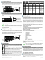
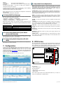
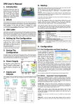
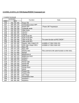
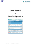
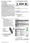
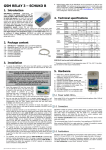
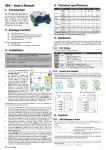
SP10 – User’s Manual 6. Run SeaConfigurator (Windows Start: Programs SEA Configurator Configurator). Connect your SP10 and your PC using a USB cable which is a part of the package. USB connector (B) is located under the small square cover on SP10 (see the picture). When configuring SP10 with a USB cable, SP10 must be connected to the power supply! Load the configuration from SP10 by clicking the [From station]. Enter your phone number and name on the "User List". 7. Modified configuration must be written to SP10. Click the [To station]. If you leave the USB cable connected, you can monitor the current state of SP10 inputs, outputs and status. 8. Digital inputs (signals to SP10) are connected to terminals X1 to X9 and digital outputs (signals out of SP10) are connected to terminals Y1 to Y8. Schematics of these signals are listed in the "Hardware" section. In the event of any change on any input SP10 can send to your mobile phone the SMS message in the form as "Input1 is closed" (the text depends on SP10 configuration). 1. Introduction GSM-SP10 (SP10 for short) is a device for remote control and monitoring via GSM network. SP10 has 8 digital outputs, which can be changed or can generate pulse depending on SMS command or a voice call, 9 digital inputs. SP10 can react on these inputs by sending a SMS and/or by a voice call and one analog input (terminals A1+, A1-) which can be configured as current input (0 to 20mA), voltage input (0 to 10V) or temperature input (for various temperature sensors). SP10 is equipped with an internal backup battery, so it can operate even during power supply failure. When long time operation on the battery is needed, “Power saving” mode can be activated in configuration in which SP10 disconnects itself during several minutes from GSM network to minimize the power consumption. Detailed data of SP10 activities can be logged into file in a MicroSD card. Functions and names of inputs and outputs, phone numbers, password, etc. are fully user configurable using a personal computer via the USB cable or remotely via GPRS data using program SeaConfigurator which can downloaded free of charge on a webpage www.seapraha.cz (fill in the word “CONFIGURATOR” into an entry field of the “Search tool”). SP10 has an integrated DIN rail mount, so you can comfortably place it into a cabinet. (1) SIM card holder (located under the removable cover) (2) MicroSD card holder (located under the removable cover) (3) USB connector (under the square cover) 12 (4) 8 outputs (Y) (2 x 4) (5) DIN rail holder (6) Power supply (8 to 30 VDC) 1 (7) LED for outputs status indication 2 (8) LED for SP10 status indication 3 (9) LED for inputs status indication (10) Analog input (0 to 10V; 0 to 20 mA; temper.) (11) GSM antenna connector (12) 9 Digital inputs (X) pc pc pc pc pc Parameter Dimensions 10 9 Supply 8 7 6 4 5 Digital inputs DC (any polarity) Digital outputs DC, AC GSM-SP10 GSM antenna (order code GSM-ANT05S) USB cable A-B (order code HW-11.02.8818) MicroSD card (2 GB) printed documentation (this manual) Accessories - has to be ordered separately! Box with power supply 230V GSM-SP-BOX-MV Temperature sensor GSM-C-T2 range -20 °C to +50 °C, based on sensor KTY81-210 Expansion Input Module GSM-SP-EXP (9 digital + 7 analog. inputs) Communication module RS232 (GSM-SP-CB2) or RS485 (GSM-SP-CB5) Warning! GSM module Do not connect wires to analog inputs before analog inputs are properly configured! Memory card Note: The PIN is possible to activate later when the user became familiar with the configuration procedure of SP10. 1. Before power on the device SP10 insert an activated SIM card (= call the helpline of your GSM operator) to the SIM card reader (under the removable cover) and connect the GSM antenna. The SIM card is inserted into the reader by cut corner down and contacts to the center of SP10. Proper insertion can be identified by a mechanical click. The SIM card can be removed by gently pressing (until you hear a click) and release. Now the SIM card can be freely pulled out. 2. Connect the power supply voltage from the DC voltage source 8 to 30 VDC to the terminals + and – and power on the power supply. 3. If the power supply is OK, the green LED PWR lights. At the same time after ca. 20 seconds the blue LED GSM will briefly flash in the interval 1 time per 3 sec. 4. Send the SMS text message from a mobile phone in form 1234 STATE to the phone number of the SP10. The device responds with a status message in the form "Test SP10: Window = Closed elevator Heating system = OK = ON SIGNAL = 53%.". To use other functions it’s necessary to configure the device using the program SeaConfigurator, see below. 5. Install the program SeaConfigurator. The current software version can be downloaded (free of charge) on the web site www.seapraha.cz (fill in the word “CONFIGURATOR” into an entry field of the “Search tool”). Please follow the instruction during installation. USB driver is installed automatically with SeaConfigurator. GSM-SP10 User’s Manual EN v1-07 / 2014-05-07 Conditions TYP. 60 90 MAX. 80 Unit mm mm mm 53 *) Slim) VCC ICC PCC 8 2,5 9 12 8 |VIN| IIN VOUTDC VOUTAC IOUTDC IOUTAC - <4 5 8 VIN = 12V 30 4 50 35 100 70 1 analog input configurable for voltage, current, temperature measuring with calculation into users unit: 0 to 10V; 0 to 20mA (input resistance 75 ); temperature sensors: KTY (-50 to +150°C); Pt100 (-100 to +300°C); Pt1000 (-100 to +300°C); maximum 12 maximum 50 voltage 100 - RIN current - Operating Operating 30 0,5 VCC = 12V |VIN| Voltage Current Input resistance Input resistance Resolution Band Temperature Rel. humidity MIN. d Analog input A1: 3. Installation Before inserting the SIM card into the SP10, it is highly recommended to turn off setting of the “PIN code”! Insert the active SIM card (= at least one call was made) to any mobile telephone and turn off the requirement of setting the PIN. On most mobile telephones, this option can be found in menu “Setting the telephone protection” or “Setup -> Security -> PIN control”. Symbol w h Width Height (w/o GSM antenna) Depth (between DIN rail and cover) Voltage DC Current Average power consumption Number Voltage log. H Voltage log. L Current Number Voltage DC Voltage AC Current DC Current AC Number Measured value 11 2. Package 1 1 1 1 1 4. Technical specifications V V mA VDC VAC mA mA - V mA k 75 12 850/900/1800/1900 MicroSD card 3VDC - SD, SDHC, (SDX not supported) -20 +45 90 tA hA VDC A W bits MHz °C % SP10 is designed to be mounted into a cabinet with IP44 or better! 5. Hardware GSM antenna Inputs X4 X6 X8 A1COM X2 X3 X5 X7 X9 A1+ X1 1 3 5 7 SMS PROCESSOR GSM – SP10 7 2 4 6 8 SP9 under the top cover Input status LED indication SIM card Connector reader tor expansion board or unit IN(X) PWR SP10 status GSM LED indication ERR 8 MicroSD Card reader OUT(Y) USB www.SEApraha.cz 1 2 3 4 5 6 Button Output status LED indication Y4 Y5 Y7 Y8 C1-C4 Y2 8-30V + Y3 C5-C8 Y6 DC Y1 Outputs Terminals A1-, A1+ (analog intput): … voltage input 0 to +10VDC (connect terminal A1+ to higher potential!) … analog input 0 to +20 mA (connect terminal A1+ to higher potential!) … temperature sensor KTY81-210 (polarity does not matter) Warning It’s highly recommended to use the extra power supply for SP10 power, galvanically separated from the power supply for input and output external circuitry, especially when I/O have long wires, that may be noisy. page #1 of 4 5.1 Digital inputs (X) Digital inputs (SP10 input signals) are labeled X1 to X9. The COM terminal is common for all digital inputs. The figure shows an example of the connection of external circuits, and internal wiring of input X1 (same for all digital inputs). The polarity does not matter - COM can be connected either to plus or to minus. External power supply 8 to 30 V DC + SP10 Internal wiring of input X1 LED COLOR PWR green GSM blue ERR red Inputs Meaning Dark Device Power OFF no GSM signal normal operation Light Blink 1x per 3sec Power ON or battery powered other GSM error - - normal operation SIM card problem Error Error Error 1 to 8 (IN) green input not activated input is activated - during transition time before input status is accepted after input change (before SMS can be sent) 1 to 8 (OUT) green output not activated output is activated - - 3k9 X1 Inputs 1k COM X4 X6 X8 A1COM X2 X3 X5 X7 X9 A1+ X1 5.2 Analog Input (A) SP10 has 1 analog input (A1), which is connected to the input terminals (labeled A1+, A1-). Analog input can be configured for measuring of voltage (0 to +10V DC), current (0 to 20mA) or temperature using temperature sensors (KTY81-210, Pt100, Pt1000). SP10 Analog input SP10 Analog input Input configuration for: A+ + Inputs A- - X4 X6 X8 A1COM X2 X9 A1+ X3 X5 X7 X1 voltage 0 to 10VDC; current 0 to 20mA; Temperature sensor KTY-81, Pt100, Pt1000 The measured values can be converted to user units. For example the measured current from 4 to 20 mA can be displayed as the pressure of 0-5 MPa (see the configuration program SeaConfigurator). Warning! Do not connect wires to analog inputs before analog inputs are properly configured! Otherwise the inputs can be damaged. (E.g. when an input is configured as temperature, it must not be used to measure voltage or current!). Use only passive (resistive) temperature sensor when input configuration is for temperature measuring. 5.3 Digital outputs (Y) Digital outputs are labeled Y1 to Y8. The terminal C1-C4 is common for outputs Y1 to Y4 and the terminal C5-C8 is common for Y5 to Y8. The figure shows an example of the external and internal wiring circuits of output Y1 (the same for all digital outputs). Y2 output switches negative branch power relay coil and vice versa Re2 Y6 output switching power supply positive branch of the relay coil Re6 (relay voltage must correspond to an external source voltage!). The polarity of the terminals C1-C4 and C5-C8 terminals is irrelevant - can be plus or minus. SP10 Y4 Y7 Y8 Y5 C1-C4 Y2 8-30V Y3 C5-C8 Y6 + DC Y1 Outputs Internal wiring of output Y1 Y1 Výstupy C1-C4 0,2A Re2 + Re6 Power supply of SP10 8 to 30 V DC 5.5 MicroSD card SP10 can store detailed information of its activities into a log file on a MicroSD card for later analysis. The MicroSD card reader is located under the removable cover close to the SIM card reader. A user can use SeaConfigurator to setup which data will be written into the log file (e.g. input and output statuses, changes, analog values, incoming and outgoing SMS messages). Log file format is standard .csv file (= Comma Separated Values). The file name depends on the actual date (datum.csv). In case there are more files created during one date the filenames are distinguished by “@” sign followed by characters ‘A to ZZ’ (e.g.: 130205.csv; [email protected]; [email protected]; [email protected]; etc.). This usually happens after SP10 reset or configuration changes, manipulation with MicroSD card or SIM card. Logged file can be erased only manually on PC. There are two types of logged records: periodical and event (I/O changes). Event record contains actual analog values. Periodical log file can contain average / minimum / maximum analog value. Typical logged values: LocalTime;type;phone;text;Y1;Y1.cmd;Y2;Y2.cmd;Y3;Y3.cmd;Y4;Y4.cmd;Y5;Y5.cmd ;Y6;Y6.cmd;Y7;Y7.cmd;Y8;Y8.cmd;X1;X2;X3;X4;X5;X6;X7;X8;X9;PWW;AP;A1;ALM1 ;Batt.Chg;Batt.Cap;T.int;Ubat;Inab;GSM.cell;GSM.signal;GSM.credit; Example of one record of data: 2014-05-04 14:15:43;1;;;0;;0;;0;;0;;0;;0;;0;;1;;0;1;0;0;0;0;0;0;0;1;16,1;17,6;0; 100;?;27,5;4209;1;23002F,2F20,049E_0030;38;; Type of recorded data: 1 – regular by time 2 – extra caused by change of digital input or output 3 – incoming SMS 4 – outgoing SMS 5 – phone call outgoing 6 – debugging information Y.cmd: B ... alert A ... alarm Q ... reset P ... pulse N ... not freezing temperature Number ... regulation function + + External power supply 8 to 30 V DC Blink Fast 1:1 SP10 needs a MicroSD card formatted as FAT16 or FAT32 with directory “LOGGER” in the root directory (C:\LOGGER). 5.4 Front Panel 1 3 5 7 2 4 6 8 The front panel of the SP10 includes status LEDs of inputs, outputs and status of of SP10. The states are only shown for inputs X1 to X8 and all outputs Y1 to Y8 (LED for Y7 and Y8 are located above the USB connector). In case an input or output is switched on its LED number lights or blinks. IN(X) PWR GSM ERR Under the removable cover is placed the SIM card reader, the MicroSD card reader, the button (for turning the device into “sleeping mode”) and a connector for connecting of an expansion board (GSMSP-CB2 or GSM-SP-CB5) or an expansion module (GSM-SP-EXP). The SIM card is inserted into the reader (cut corner down) and contacts to center of SP10. Proper insertion can be identified by a mechanical click. SIM card can be removed by pressing gently on it (until a click) and release. Then the SIM card can be pulled out. (Operation with the MicroSD card is similar). An expansion connector is intended for connection of a communication board or (using a flat cable) expansion unit which can be located on left side of the SP10 on a DIN rail. The USB connector for connection to the PC is hidden under the square cover. OUT(Y) 1 2 3 4 5 6 GSM-SP10 User’s Manual EN v1-07 / 2014-05-07 Warning Check, if the MicroSD card is formatted as FAT16 or FAT32 and contains directory “LOGGER” in the root, before insertion into SP10. 5.6 Backup battery SP10 is equipped with an internal Li-Ion battery, so it can operate without connection to the power supply. When long time operation on the battery is needed, so called “Power saving” mode can be activated in configuration in which SP10 disconnects itself during several minutes from GSM network to minimize the power consumption. SP10 is “awakened” by an event on specified digital or analog inputs or after specified time period. This cycle repeats until the power supply is restored or special SMS which cancels the “power saving” mode is received. 6. Remote Control 6.1 SMS Message control SP10 is controlled via SMS messages of GSM network. Command SMS messages are in form: <PASSWORD> <COMMAND> [<RETURN COMMAND >] page #2 of 4 Example: 1234 STATE 1234 DOUT1 ON be returned 1234 DOUT8 PULSE confirmation message … SP10 returns an SMS containing status … SP10 output1 will be switched on. Confirmation SMS will 7.1 Important Terms Explanation NOBACK … SP10 pulse on output8 will be generated, no will be sent back PIN (Personal Identification Number – usually four digits number). Only persons with knowledge of PIN can operate a SIM card (in case the PIN usage on a SIM card was activated). Usage of the PIN can be deactivated. Insert the SIM card to your mobile phone and follow the instruction in the mobile phone manual. (Usually the PIN usage can be deactivated in Menu -> Security -> PIN). It’s possible to write more commands into one command SMS. For higher readability separate commands by semicolon “;” inside command use “=”. 1234 OUTPUT0=ON; OUTPUT1=ON; OUTPUT3=PULSE; Names of inputs and outputs are user definable by SeaConfigurator. Command SMS may look like this: 1234 GATE=OPEN; HEATING=ON; LAMP=BLINK 6.2 Status SMS Text Message Whenever command SMS contains valid password, SP10 always sends back status SMS. Status SMS contains following information: <Device Name>: <LogInput1>=<LogInput1Status> <LogInput2>=<LogInput2Status> ... <LogOutput1>=<LogOutput1Status> <LogOutput2>=<LogOutput1Status> ... <GSM Signal Level> Status SMS message contains only information concerning selected inputs and outputs. Selection is done using configuration program SeaConfigurator by checking the appropriate checkbox. Status SMS example DEVICE SP10: Din1 = on Din2 = off DOout3=on SIGNAL=58% Explanation Device Name (user configurable) Digital Input 1 is on Digital Input 2 is off Digital Output 3 is on (closed) GSM Signal level in % 6.3 Control using SeaControl (from Smart phone with Android) This application can be used in smartphones with OS Android. It makes it easy to control and monitor SP10 states. This application can be installed free of charge from Google Play after insertion of word “seacontrol”. 6.4 Control using SeaConfigurator (PC with WIN) Control outputs and monitor SP10 states is also possible from the configuration sw SeaConfigurator on a folder „Monitoring“. 7. Configuration ACCESS CODE = Password for SMS commands, configuration and monitoring of SP10 accepts only SMS with a valid access code. The password is requested also for connection of SP10 (via USB cable or remotely via data connection of GSM network). Factory setting of access code is “1234”. EVENT = level change in case of digital input, zone change in case of analog inputs. SP10 can react on EVENTS by several ACTIONS if it is setup this way. SP10 can send SMS messages on selected phone numbers and/or to make voice calls on selected phone numbers. ACTION = one voice call or one SMS to one user. Any EVENT can contain several ACTIONS. COMMAND is sent using SMS to device or is possible to caused it as an ACTION in case of EVENT. This type of command is called “INTERNAL COMMAND” and has the same rules as COMMND in SMS, except PASSWORD which is not necessary. USER LIST = List of all users and their phone numbers which are used for ACTIONS. User names are used only for better clarity. SP10 does not use them in any way. DEVICE OFF = Disconnection of SP10 from any form of power supply (including internal battery). DEVICE ON = Connection of SP10 to any form of power supply. (Processor reset has the same effect). POWER ON/OFF = Connection/disconnection of supply terminals from external power supply. (SP10 supplied from internal battery can send SMS about Power recovery and Power outage). 8. SP10 in box SP10 can be placed into a special box (order code GSM-SP-BOX-MV) equipped with power supply 230VAC/12VDC (type GSM-PWR1). Empty space on the left side of GSMSP10 is intended for the expansion digital and analog inputs module GSM-SP-EXP. On the BOX is mounted the panel SMA connector for antenna connection. For local and remote configuration of SP10 and local and remote monitoring is used special program called SeaConfigurator. The USB cable can be used for local configuration/monitoring. GPRS data connection can be used for remote configuration/monitoring. Actual version of SeaConfigurator can be downloaded free of charge on the website www.seapraha.cz (fill in the word “CONFIGURATOR” into an entry field of the “Search tool”). GSM anténa Vstupy X4 X6 X8 A1COM X2 X3 X5 X7 X9 A1+ X1 1 3 5 7 SMS PROCESSOR Example - Configuration program SeaConfigurator basic screen: GSM – SP10 7 + 12V - 2 4 6 8 IN(X) PWR GSM ERR POWER SUPPLY 230V~ / 12V= 8 OUT(Y) USB www.SEApraha.cz 1 2 3 4 5 6 Y4 Y5 Y7 Y8 C1-C4 Y2 8-30V Y3 C5-C8 Y6 + DC Y1 GSM-SP-BOX-M GSM-PWR1 L N Výstupy GSM-SP-BOX-MV 230V~ Box parameters: Ingress Protection: IP55 Outer box dimensions: Width: 166 mm Height: 140 mm (without connectors) Depth: 150 mm Next to power supply and SP10 can be placed GSM-SP-EXP or 8 pcs of relay in a socket (e.g. GSM-RELE-OUT or GSM-RELE-OUT1). GSM-SP10 User’s Manual EN v1-07 / 2014-05-07 page #3 of 4 10. Frequently Asked Questions 9. Troubleshooting Problem Problems during installation of SP10 SP10 is not available on GSM network Possible reason Solution No power supply Check power supply Bad or not activated SIM card Test the SIM card in your mobile phone Low credit on prepaid SIM card Check the credit on prepaid SIM card (contact your operator if necessary) Phone calls are redirected Cancel all phone calls redirection 1. What is necessary to use SP10 successfully? SIM card capable to send and receive SMS messages from a standard mobile phone and voice / data call incoming and outgoing as well. Please test all these functions in your mobile phone. It’s important to solve all possible problems before using the SIM card in SP10. Contact your mobile operator if necessary. Low level of GSM signal Problems during operation of SP10 Check the connection of GSM antenna. Check the GSM signal level in the place where is located GSM antenna for SP10 (Use your mobile phone with SIM card from SP10). Signal level has to be at least two bars. Low credit on prepaid SIM card Check the credit on prepaid SIM card (contact your operator if necessary) Prepaid SIM card is no longer valid because credit was not paid for long time. Usually for more than a year. Contact your GSM (mobile phone) operator if you have any problem with SIM card in your mobile phone. Other reason Test the SIM card in your mobile phone. (Sending, receiving SMS, voice call, data call). Check the SCA center setting on SIM card and in SP10 configuration. Try to identify the cause of problem using LED diodes. Problem with remote configuration via GPRS SIM card has not active GPRS data Contact your mobile operator to be sure GPRS data tariff is active for SIM card in SP10. Good quality GSM signal in area of installation of SP10 (at least 2 bars on your mobile phone). If there is a problem with GSM signal quality, try to use another type of external antenna, which can be placed in proper place with better GSM signal and which is connected to SP10 with several meters long coax cable with SMA connector. Sufficient Credit (in case of prepaid SIM card) Cancel all phone calls redirection (and all automatic operators voice announcement) for a SIM card in SP10. 2. What is a phone number of SCA (SCA = Service Center Address) of my mobile operator? (It’s not possible to send an SMS). Contact your mobile operator for this piece of information. 3. I’ve tested SP10 with my own SIM card. Now I cannot find SMS messages formerly stored on my SIM card. SMS from your SIM card were processed by SP10 and then deleted. They were very probably canceled due to syntactical error. 4. Where can I find more (and up to date) information? Search GSM-SP10 product on the website www.seapraha.cz English pages 11. Warranty General warranty period is 12 months after purchase, when eventual malfunction device will be repaired free of charge in SEA company while shipping to SEA is paid by customer and SEA pays for shipping back to customer. For SW there is 24 months warranty under following conditions: Both CPU and PC software is sold “as is”. The software was created by the best software engineers in SEA and was carefully tested both in SEA and also by SEA customers using GSM applications products made in SEA. In spite of making all possible to get error free software it can happen, that the software in CPU or PC programming SW or their mutual interaction has some error under some specific conditions. If such error is found and the description of the problem including configuration file is sent by E-mail to SEA ltd., the error is removed free of charge and SEA will send new SW by E-mail to customer. SEA ltd. has NO RESPONSIBILITY for any damage, lost, costs and any other problems direct or inducted, caused by such SW error, by eventual device malfunction from any reason or by undelivered SMS from the device. CE Declaration of conformity in accordance with the Radio and Telecommunications Terminal Equipment Directive 1999/5/EC (R&TTE) and Directive 2011/65/EU (ROHS). We SEA, spol. s r.o., Dolnoměcholupská 21, CZ 102 00 Praha 10, Czech Republic, ID: 47117931 (manufacturer) declare under our sole responsibility, that product device for remote control and monitoring type GSM-SP10 is in conformity with the following standards: health and safety: EN 60 950-1:2005+A1:2009 EN 60 950-1:2006+A11:2009+A1:2010+A12:2011 EMC: ETSI EN 301 489-1 ETSI EN 301 489-7 v1.3.1 radio frequency: EN 301 511 v 9.0.2 The last two digits of year in which the CE marking was affixed: Place of issue: Praha Date of issue: 2.9.2013 GSM-SP10 User’s Manual EN v1-07 / 2014-05-07 Name: Grade: 13 Ing. Vladimír Rosůlek director page #4 of 4