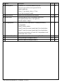
1
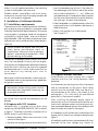
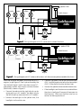
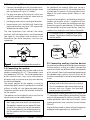
User Manual
LokSound
Suitable For LokSound mfx Decoder
1st Edition, 07/2005
User Manual LokSound mfx, 1st edition, 07/2005
1
contents
1.
2.
3.
3.1
3.2
3.3
3.3.1
3.4
3.5
3.6
4.
4.1
4.2
4.2.1
4.2.2
5.
5.1
5.2
5.2.1
5.2.1.1
5.2.1.2
5.2.1.3
5.2.1.4
5.2.1.5
5.2.2
5.3
5.4
6.
8.
7.
8.
Introduction ..................................................................................................................... 3
Characteristics of LokSound mfx decoders ....................................................................... 4
Installation of LokSound decoders ..................................................................................... 5
Installation requirements ................................................................................................. 5
Engines with DCC interface .............................................................................................. 5
Engines without interface ................................................................................................ 5
Connecting DC motors ..................................................................................................... 7
Connecting the speaker .................................................................................................... 7
Connecting auxiliary function devices .............................................................................. 7
Connecting a wheel sensor ............................................................................................... 8
Set up of the decoder ....................................................................................................... 8
Analogue operation with Märklin® -Transformer .............................................................. 8
Digital operation .............................................................................................................. 9
Using Märklin® 6021 ....................................................................................................... 9
Using mfx-Systems. ......................................................................................................... 9
Adjusting decoder parameters .......................................................................................... 9
Adjustable decoder parameters using Märklin® mobile station ......................................... 9
Adjustable decoder parameters when using Märklin® control unit 6020 or 6021 ................ 9
Available parameters when using 6021 ............................................................................. 10
Resetting to default values (factory pre-sets) .................................................................... 10
Load control .................................................................................................................... 10
Sound adaptation ............................................................................................................. 11
Second Märklin® address ................................................................................................. 11
Settings for analogue mode .............................................................................................. 12
Adjusting values using Märklin® 6021 ............................................................................... 12
Decoder parameters that can be set with the Märklin® central station ............................ 12
Adjusting decoder parameters using the ESU LokSound Programmer Art.No. 53452 ................... 12
Frequently asked questions (FAQ) ..................................................................................... 13
Service, support and assistance. ....................................................................................... 13
List of all supported CVs ................................................................................................... 14
Specifications for LokSound mfx ...................................................................................... 16
Copyright 1998 - 2005 by ESU, LLC. Electrical characteristics and dimensions are subject to change without prior notice. All rights reserved. ESU may not be
held responsible for any damage or consequential loss or damage caused by inappropriate use of the product, abnormal operating conditions, unauthorized
modifications to the product, etc.
Not suitable for children under 3 years of age. Inappropriate use may result in injury due to sharp points and edges.
Märklin® is a registered trademark of the company Gebr. Märklin® und Cie. GmbH, Göppingen, Germany.
2
User Manual LokSound mfx, 1st edition, 07/2005
1. Introduction
Congratulations on purchasing a LokSound mfx
decoder! With LokSound mfx your engines will sound
like the prototype. You will soon notice that your
LokSound mfx equipped engines are the center of
attraction on any layout.
Handle speakers with extreme care: Do not
touch the membrane or apply pressure! Solder
speaker connections quickly and only at the
intended contacts! Pay close attention to the
instructions for installing the speaker!
Of course, you would like to install this decoder
immediately, but first we have a request:
If you adhere to these warnings your LokSound mfx
decoder will reward you with long life and troublefree operation.
Please read this manual carefully prior to
installation!!! Although LokSound mfx decoders are
very robust, incorrect wiring may destroy the
module!
Due to its factory settings your new LokSound mfx
decoder can generally be used as is. In addition it
offers a multitude of options to help you adjust your
LokSound mfx decoder even better to your model.
Please familiarize yourself with the decoder before
installing it and adjusting any parameters. Also note
the recommendations regarding installation.
Important warning:
• LokSound decoders are designed for use in model
railways only
• Avoid mechanical force or pressure on the decoder
• Do not expose to wet and humid conditions
• Do not remove the heat shrink sleeve on the
decoder
• Never solder on board, extend cables if necessary
• Never wrap the decoder in insulation tape, since
this may prevent heat dissipation and cause
overheating
• Always disconnect from any electrical power
sources when installing the decoder
• Make sure that neither the LokSound decoder
nor any blank wire ends may come into contact
with the engine chassis (risk of short circuit). Cover any blank ends of unused wires.
• Make sure that no wires are squeezed or cut by
the model’s transmission parts when reassembling
the engine.
• When reassembling the engine , make sure that
no wires are squeezed or a short circuit could
occur.
User Manual LokSound mfx, 1st edition, 07/2005
ESU, LLC, July 2005
This manual has several Chapters explaining step by
step how to proceed:
Chapter 2 provides an overview of the
characteristics of LokSound mfx decoders.
Chapter 3 describes installation and connection of
LokSound mfx decoders.
LokSound mfx decoders are suitable for most digital
command control systems that either work with the
Märklin Motorola data format (e.g. control unit 6020,
6021) or the new mfx-data format (e.g. mobile station
or central station). Of course LokSound mfx decoders
can also be used on conventional AC layouts. Chapter
4 provides an overview on which digital and analogue
systems may be used to operate LokSound decoders
as well as some particularities of certain systems.
If you want to modify the preset running
characteristics and/or sound effects, we strongly
recommend reading Chapter 5. Here you will gain
an insight regarding the many options and how to
adjust various parameters of the LokSound mfx
decoder with different systems. You will also learn
how to reset the decoder to the factory settings.
Depending on the type of central unit not all functions
may be available.
For easy setting of parameters we recommend either
the Märklin central station or the ESU LokSound
Programmer (Art. No. 53452). Both systems offer a
graphic display, which makes setting any parameter
of your LokSound decoder a simple task.
In Chapter 6 we comment on frequently asked
questions in greater detail.
In Chapter 7 a table provides all you need to know
regarding the programming of decoder
characteristics as outlined in Chapter 5.
3
2. Characteristics of LokSound mfx decoders
The LokSound mfx decoder is a universal electronic
module for installation in model engines preferably
in HO gauge AC models. The LokSound mfx
revolutionizes authentic model train operations: It
intelligently combines a sophisticated digital decoder
and a digital sound module. With LokSound mfx you
can run your engine with load control and many
auxiliary functions while enjoying the original sound
of the prototype. Its unique features provide flexibility
and reliability in operation that you have come to
expect from a state-of-the-art decoder. Even future
standards are no problem for LokSound: its flash
technology allows adaptation to the latest
developments. All you need for updating is the
LokSound Programmer Art.No. 53452.
Multi-protocol operation: The LokSound mfx
decoder was specially developed for models with a
center pick-up (3-rail operation). Trouble-free
operation with all Märklin® / Motorola® – central
units was the main design objective. Furthermore
100% compatibility with Märklin® systems and its
data format mfx was paramount thus providing
maximum user comfort with mfx.
Fully automatic change between all 3 operating
modes „on-the-fly“ (AC analogue, mfx digital,
Motorola® digital)
Motor types: the following motor types may be
connected to LokSound mfx:
• DC motors (e.g. Bühler, Mabuchi)
• Coreless motors (e.g. Faulhaber, Maxxon)
• Universal motors with HAMO-conversion
(thus converting the universal motor to a DC motor)
High motor pulse frequency: due to the pulse
frequency of 32 kHz (!) the motor is operated in the
best possible way. Therefore the motor not only runs
silently (no singing or humming), but will also be cooler
and have a longer life. LokSound mfx decoders are
particularly suitable for coreless motors.
Motor control: the LokSound mfx has 4th generation
load control: you can adapt it to your motor or turn
it off. When activated, your engine will travel at a
constant speed regardless of the load or if the engine
travels up or down a gradient. Motor control is preset for operation with Märklin® 6090x high
performance drives respectively universal motors
with HAMO-conversion.
4
4 function outputs: Besides the two lighting outputs
there are two additionalauxiliary function outputs
available: Turn on the smoke generator or the interior
lights remotely or decouple by pushing a button on
your central unit! Lighting effects and individually
dimmable lights provide fun experienced never
before when “playing“ with your trains and absolutely
realistic models.
Brake sections: The LokSound mfx decoder
understands (and responds to) the Märklin®-brake
section.
Protection: both the motor output and the function
outputs are protected against short circuits as far as
possible.
Please make sure that the maximum
permitted current for the function outputs
may not be exceeded under any
circumstances. Also prevent short circuits
across the outputs: although the LokSound mfx
has protective circuitry it is subject to
damage or destruction if an external power is
supplied to the output terminals.
Analogue mode: LokSound mfx decoders can be
operated on AC layouts without any problems.
Easy adaptation: Even with the Märklin® 6021 you
can adjust most parameters comfortably without
opening the locomotive. It is even easier with mfxcentral units or with the ESU LokSound Programmer.
• A digital, four channel sound module with unique
features:
Prototype sounds: sounds of prototype engines
were sampled using high fidelity microphones and
recorded digitally on the flash memory module. Thus
your engines sound exactly like the prototype!
With four independent channels your engine sounds
even more realistic since you can simultaneously
add 3 sound effects to the running sound. Pumps,
power switches and squealing brakes can all be heard
at the same time.
LokSound mfx allows you to hear the exhaust chuffs
of steam engines as they vary with the revs of the
drivers and the load. Now you can really hear your
engine work. Diesel engines can now simulate the
reduced revs of the diesel while the engine is coasting.
The running sound and the sound of the fans (blowers)
in electric engines are now separated.
User Manual LokSound mfx, 1st edition, 07/2005
Pressing a function button triggers additional sound
effects. On mfx capable controllers, the matching
symbol is displayed at the same time.
Random sounds: sound effects such as air pump,
water pump, fireman Fred, discharging compressed
air, etc. are randomly triggered.
3. Installation of LokSound decoders
3.1 Installation requirements
The engine must be in good mechanical condition:
only an engine running smoothly in analogue mode
should be modified for digital operation. An engine
running poorly in analogue mode will not operate
satisfactorily in digital mode – even with the best
digital decoder. Check and clean or replace any wear
and tear parts such as motor brushes, wheel contacts,
lights etc.
Always remove the engine from the track
when doing maintenance work or
modifications. Make sure that no voltage is
applied – intentionally or accidentally – while
you are working on the model.
Please keep the plug / relay for future use.
• Insert the decoder plug with pin 1 (the side with
the red/orange wire) into the side of the socket
that is usually marked with *, +, . or 1. Make sure
not to bend any pins. Do not rely on the assumption
that the wires have to lead in a certain direction;
the marking is the only valid reference.
• Place the decoder in a suitable location within the
engine and fasten it with double sided tape or a
drop of hot glue.
• Now fix the speaker in a suitable place.
See Chapter 3.4
Pin Description
1 motor terminal right
2 rear light
3 function F1
4 current pick-up 1
5 motor terminal left
6 headlight
7 common (+pole)
8 current pick-up 2
Color Code
orange
yellow
green
black
gray
white
blue
red
red
LokSound mfx decoders have a certain size: make
sure, that the decoder fits easily into the engine,
that no pressure is applied when replacing the housing
onto the chassis and that no wires are squeezed
between other parts. Further, make certain that no
wires obstruct any moving parts such as
transmissions.
3.3 Engines without interface
Never pack a LokSound decoder in foam pads etc.
The decoder heats up during operation; good heat
dissipation is essential.
Unfortunately not every engine has a digital
interface and thus the wiring becomes more
elaborate:
Electronic components are sensitive to
electrostatic charges: always make sure that
your work place is grounded. If necessary, use
an earthed wristband.
First disconnect any existing wires within the engine
and any connection to the chassis. Both motor
contacts must be insulated. Make sure there isn’t
any connection to the chassis, the wheels or the
pantographs. This may easily be overlooked
particularly in Fleischmann models!
After installing the decoder please check all
connections with an Ohmmeter and check for any
short circuits between motor- and current pick-ups.
How to proceed depends on how the headlights and
other functions are wired in the engine:
When installing the decoder make sure that no metal
part of the chassis touches any components of the
decoder.
3.2 Engines with DCC interface
LokSound mfx is supplied with an 8-pin plug
conforming NEM 650/652 (NMRA S9.1/9.2) as shown
in figure 1. Therefore installation in engines with a
NMRA socket is particularly easy:
• Remove the body! Follow the instructions in the
manual of the engine!
• Remove the analogue plug or directional relay.
User Manual LokSound mfx, 1st edition, 07/2005
black
1: NMRA interface
Figure 1
a) If headlights and functions are insulated from the
engine chassis (free of any voltage) proceed as per
figure 2.
b) Headlights and functions are connected with their
common to the track voltage (e.g. almost all
5
speaker100Ω
purple
green
yellow
white
AUX 2
AUX 1
light
light
2 x dark brown
LokSound
LokSound
mfx
blue
black
red
orange
gray
engine
Figure 2
2: Wiring of engines with DC motor and insulated functions
speaker100Ω
purple
green
yellow
white
AUX 2
AUX 1
light
light
2 x dark brown
LokSound
mfx
chassis
orange
black
red
gray
engine
Figure 3
3: Wiring of engines with DC motors and functions with the common pole connected to the chassis
Märklin® -engines and older Fleischmann or ROCO
engines) as per figure 3. Don’t get confused by the
fact that both figure 2 and 3 show how to wire DC and coreless motors. How to wire a universal motor
(Märklin®) is shown in figure 5.
• Connect the red wire to the right rail pick-up (or
center pick-up in AC models), the black wire to
the left rail pick-up (common rails in AC models).
• Connect the green wire to the function output
AUX-1 and the purple wire to the function output
AUX-2. Allocate the function buttons later.
• Connect the speaker to the two dark-brown wires.
• If the headlights and functions are insulated from
the chassis (see figure 2) connect all commons to
the blue wire. Make sure the blue wire has no
contact to the engine chassis!
• Connect the rearlights to the yellow wire, the
headlights to the white wire.
6
User Manual LokSound mfx, 1st edition, 07/2005
3.3.1 Connecting DC motors
• Connect the orange wire with the motor terminal, which was originally wired to the right wheel
pick-up (center pick-up in AC models).
• The gray wire goes to the terminal, which was
originally connected to the left wheel pick-up
(common rails for AC models).
• Exchanging wires causes a change of direction.
• Some engines with the Märklin® 5-pole high
performance drive may have 3 RFI suppressors
soldered to the motor shield.
The two suppressors that connect the motor
terminals with the motor chassis must be removed
(see figure 4). Any chokes have to remain in the
locomotive for radio frequency transmission
suppression.
remove capacitor
orange
Connect the speaker to the 2 dark brown wires of
the LokSound mfx module. Make sure to use a
small soldering iron (max. 20 W) and only heat the
marked spots as shown in the figure (close to the
edge of the small contact plate). Polarity is not
important.
An optimal sound effect is achieved by putting the
speaker into a baffle, which is supplied with the
speaker. This will increase the sound pressure and
channel the sound in one direction. Without baffle
the sound effect may be unsatisfactory. Feed the
speaker wires through a small hole in the baffle.
A suitable baffle is supplied with each
speaker. The speaker should be fitted tightly
into the baffle.
speaker
gray
Figure 4
4: 5-pole Märklin® high performance drive
3.4 Connecting the speaker
LokSound mfx decoders may only be used with the
speakers supplied by ESU, LLC. These speakers have
an impedance of 100 Ohm. The use of speakers from
other manufacturers may cause considerable
distortion and in extreme cases may even destroy
the LokSound decoder.
The correct position of the speaker is crucial to
achieve high quality sound. A speaker that is installed
without a baffle will not generate good sound.
Therefore carefully select the location and baffle
for the speaker.
The speaker must be installed in such a way that the
sound waves are not unduly blocked.
Please handle speakers with extreme care:
don’t apply pressure or touch the membrane!
The speaker’s magnets are very powerful! Keep
all metal items away and secure the speaker
firmly when soldering. The soldering iron may
pull the speaker due the magnetic field and
destroy it.
User Manual LokSound mfx, 1st edition, 07/2005
baffle
solder here!
3.5 Connecting auxiliary function devices
Any load may be connected to the lighting and auxiliary
function outputs as long as it doesn’t exceed the
maximum current (see technical data in the appendix
of this manual). Note that the overload protection of
the decoder reacts quickly and will switch off all
functions immediately in case of an overload or short
circuit.
Therefore use only lights for 16 V (or a higher
voltage) and a maximum nominal current of
50 mA: incandescent lights have a high starting
current and may trigger the overload
protection during switch-on.
Use only digital smoke generators (e.g. Seuthe No.
11) for engines whose lighting and auxiliary function
outputs are connected as shown in figure 2. Other
smoke generators draw too much current. Some
smoke generators have a nominal current of over
250 mA!
Engines that are wired as shown in figure 3 require an
analogue smoke generator e.g. Seuthe No. 10.
7
Make sure that the total current for the function
outputs does not exceed the permitted current rating
and avoid short circuits between outputs. Although
the output circuits of the LokSound mfx are
protected, a high voltage on the terminals or a short
circuit may cause damage!
3.6 Connecting a wheel sensor
To synchronize the exhaust chuffs with the revs of
the drivers an external sensor may be used. The
sensor input is described in figure 5.
The LokSound mfx decoder supports reed contacts
or mechanical contacts.
If you want to use a reed contact , (available in
hobby shops) for each exhaust chuff a miniatrure
nagnet has to be fixed on the driver axle. Thus each
magnet triggers the reed contact once per turn. The
best choice are miniature reed contacts available in
electronic stores. Suitable magnets are available in
model train stores (e.g. Mini track magnets). They
may have to be adapted using a file.
Generally speaking all 2-pole mechanical contacts
can be used as long as both poles are fully insulated
(no connection to the chassis).
The sensor has to be activated (software) before it
will actually work. Refer to Chapter 5.2.1.3
drive wheel
Before changing any decoder settings (e.g. engine
address, sound volume) we recommend to read
Chapter 5. There you find out which parameters are
available with LokSound mfx decoders and how they
may be adjusted with the DCC command stations
supported by mfx decoders.
Please check all connections carefully using
an Ohmmeter: Are there any short circuits
between the motor terminals and the wheel
pick-ups? Are all connections between motor
terminals and the chassis insulated? Are lights
connected properly and insulated from the
chassis? Is the decoder installed safely to avoid
contact with the chassis? Is there sufficient
space around the LokSound decoder to allow
for heat dissipation? Could the LokSound
decoder or any of the wires be squeezed when
refitting the housing? Is the speaker installed
in such a way that sound can emit from the
engine without obstruction?
After all the above points have been checked you
may apply power to the engine. We strongly
recommend carrying out this initial test on a track
section with over-current protection. The ESU
LokSound Programmer Art.No. 53452 has an integral current guard.
The factory pre-set address for the
Motorola®-mode is 03
The engine reports automatically to all
mfx-central units.
reed contact
Does the engine move in both directions?
Turn on the lights: are they operating correctly? If
the LokSound mfx decoder was built into an engine
with NMRA / DCC interface: check if the plug has
been inserted correctly.
4.1 Analogue operation with Märklin® Transformer
Figure 6
6: Connecting a wheel sensor
4. Set up of the decoder
After successful installation you may now operate
the LokSound mfx decoder.
The following will outline how you can check if you
have installed the decoder correctly. Chapter 4.1
describes analogue operation. In Chapter 4.2 you
learn how to operate LokSound mfx with various
digital systems.
8
Operation with conventional Märklin® AC
controllers works as you know it from other models:
turning the knob controls speed.
To change direction the knob has to be turned to the
left beyond the stop position.
Please note the following:
The engine must have completely stopped
before changing direction. Never change
direction while the engine is moving!
User Manual LokSound mfx, 1st edition, 07/2005
4.2 Digital operation
4.2.1 Using Märklin® 6021
Operation of class BR 86 is possible with all previously
marketed Märklin® control devices such as delta
control, control unit 6020, control unit 6021 or
compatible systems. The functions F1 to F4, however,
can only be activated with the “new Motorola®
format“. To activate this format put DIP-switch 2 of
the 6021 to the upper (“On“) position.
The LokSound mfx decoder offers a special feature:
besides “the normal“ address (factory pre-set: 03)
the decoder also “understands’ the following address
(factory pre-set: 04). Whenever you call up this
address with your central unit you can activate
functions F5 to F8 with function buttons F1 to F4.
Thus, even when using central unit 6021 8 functions
plus headlights are available. Since this feature
requires another address of the total of 80 addresses
it can be turned off if not required. Please refer to
Chapter 5.2.1.4
Subject to the prototype engine the function buttons
are assigned to different sound effects. A list of the
respective functions is available on our website.
4.2.2 Using mfx-Systems
The LokSound mfx decoder can be operated with
any central unit compatible with Märklin® systems
and mfx data format. Once you have placed the
engine on the track it will automatically register
with the command station and is ready for operation.
The appropriate symbols are already assigned to the
function buttons. Operation can begin immediately.
5. Adjusting decoder parameters
Chapter 5 provides information on how to change
the settings of LokSound mfx decoders. Please take
your time to read and understand the somewhat
complex explanations.
The number of the available functions and how to
adjust them varies considerably subject to the type
of central unit. The easiest way to set parameters is
by means of a PC and the ESU LokSound Programmer Art.No. 53452. Using the Märklin® central
station makes this process just as simple.
Regardless of which system was used for
programming the decoder all modifications to the
parameters will be implemented even when using a
different type of central unit. You could for instance
change some parameters with the control unit 6021
User Manual LokSound mfx, 1st edition, 07/2005
and use a mobile station for running your layout. Or
you could set all parameters with the ESU LokSound
Programmer, and subsequently run your trains with
a control unit 6021.
5.1 Adjustable decoder parameters using
Märklin® mobile station
The Märklin® mobile station is designed as a
beginners device and focuses on the most important
control elements. LokSound mfx decoders can be
operated with a mobile station without any problems
and you can enjoy the advantages of mfx:
• 128 speed steps
• Automatic registration of engine
• Display of name of engine
• Display of the first 8 functions (plus headlights)
corresponding to the selected type of sound
• Display of suitable symbol for the engine
The mobile station allows you to call up a total of 9
functions.
While the mobile station is ideally suited for running
trains, it is only possible to adjust the following
parameters of the LokSound mfx decoder:
• Name of engine
• Maximum speed
• Acceleration
• Deceleration
• Sound volume of the decoder
The mobile station is not suitable for all remaining
parameters.
5.2 Adjustable decoder parameters when
using Märklin® control unit 6020 or
6021
Prior to the introduction of the Märklin® central
station the control unit 6020 and its successor 6021
represented the fully-fledged digital command
stations by Märklin®. With the 6020 respectively
6021 the most important parameters of the
LokSound mfx decoder can be adjusted. First we will
explain which parameters can be set with these
central units; in Chapter 5.2.2 will describe how to do
it.
9
5.2.1 Available parameters when using
6021
The control unit 6021 respectively its predecessor
6020 have a two-digit display and permit you to enter
numbers from 01 to 80. Therefore, LokSound mfx
grants access to the internal configuration
parameters in such a way that they suit these
limitations. The available configuration parameters
are organized in so-called CVs (Configuration Variables).
Please note that the LokSound mfx offers far
more parameters. Within this Chapter we
only show you which parameters can be
activated with 6021. Please note that wrongly
set CVs can impair the functionality of the
decoder.
Theoretically you can enter values from 01 to 80 in
each CV. Depending on the value stored in a CV the
behavior of the decoder will vary. When looking at
the table in Chapter 7.1 you will notice that most
CVs contain simple numerical values.
For instance CV 01 contains the address in Motorola®mode. It can vary from 01 – 80 (refer to the range of
values). The factory pre-set is 03.
5.2.1.1 Resetting to default values
(factory pre-sets)
You can reset the decoder to the default values at
any time. Simply write the value 08 in CV 08. A reset
of sound files cis only possible with the LokSound
Programmer Art.No. 53452.
5.2.1.2 Load control (Back emf)
The LokSound mfx decoder has 4th generation load
control assuring that the engine always runs at the
predetermined speed regardless of the actual load.
Load control was optimised and tested with:
• Märklin®
• ROCO,
• Bachmann (Liliput),
• BRAWA,
• Bühler,
If so desired you can deactivate load control.
Influence of load control
You can adjust the effect of load control with CV 56:
Value 0 deaktivates the load control, vaule 63
represents 100% load control.
10
Parameters of load control
The internal PI-control algorithm depends on three
parameters: in CV 53 the reference voltage is set
while in CVs 54 and 55 the control components of the
PI-control are set.
Reference voltage:
In CV 53 you set the load control voltage that should
be supplied by the motor.
This value depends on the track voltage and the
coefficient of utilization of the motor. A coefficient
of 75 % and a track voltage of 16 Volts adds up to a
voltage of 16 V * 75 % = 12 Volts. That value has to
be written into CV 53. The voltage (here: 12V) is entered in 0.4V-increments. This results in a value of 30
(12V * 0.4) for CV 53. If you don’t know the exact
motor coefficient you may obtain the value
experimentally as follows:
Check, if the engine really reaches top speed at the
highest speed step or if you cannot detect any speed
changes at the top speed steps. In the latter case you
have to reduce the value in CV 53, in the first case
increase the value.
The internal PI-regulation of LokSound mfx can be
adjusted with CV 54 and CV 55. Depending on the
type of motor the parameters may have to be
adjusted to achieve optimal running performance.
LokSound mfx decoders are optimized for use
with Märklin®-motors by default
Parameter “K“, stored in CV 54, influences how
strongly load control will effect the driving
performance. The higher the value, the more load
control will respond to any changes. Adjust this value
with care, because too high values could lead to
irregular and “hard“ driving performance. If you
prefer smooth running try to reduce the value step
by step until you reach an optimum.
Parameter “I“, stored in CV 55 provides important
information to the LokSound mfx decoder regarding
the motor type used: certain electric motors respond
differently to adjustments of the rpm’s. The longer a
motor takes to respond the lower the value in CV 55.
However, it is not easy to recognize the degree of
inertia. In general: The larger the diameter of the
motor and the more poles and/or flywheels the motor
has - the more inertia it has – and the lower value in
CV 55 should be.
User Manual LokSound mfx, 1st edition, 07/2005
For optimal programming proceed as follows:
Read out the value in CV 53 as described above. Leave
the value of CV 55 (“I“) for the time being and testrun the engine. Now change the value of CV 54 in
steps of 5 downwards or upwards and observe the
running properties of the engine. If there is no
improvement leave the value of CV 54 and change
the value of CV 55 (intensity of control) in steps of 5
until an optimum is reached.
Please note that incorrectly set parameters
may impede the effect of load control to the
point that the motor may stop altogether.
Parameters for Fleischmann motors
Engines with the traditional Fleischmann motor
should be programmed as follows:
CV 54 = 60
CV 55 = 20
5.2.1.3 Sound adaptation
LokSound decoders offer many possibilities to adjust
sound effects. All parameters are stored in CVs that,
may be modified. Adaptation of revolutions for diesel
and pitch for steam exhaust chuffs. The revolutions
of a diesel motor may be modified by 2 CVs:
Enter the revolutions of the idling diesel motor in CV
59. The standard value of 32 permits reproduction of
the sound at original speed, while value 16 reduces
this to half speed.
Using a wheel sensor
The wheel sensor must be connected as described in
Chapter 3.6. Then two more parameters have to be
set:
Set CV 57 to value 01 and enter a value > =01 in CV
58. CV 58 defines after how many pulses by the sensor
the next exhaust chuff is reproduced. Normally one
exhaust chuff per pulse should be played.
Speed step dependent control
With this method the interval between exhaust
chuffs is determined with CV 57 and CV 58. This
method is recommended if an external wheel sensor
cannot be used.
The adaptation of this variable to the wheel / gearbox
combination may require some experiments. It pays
to spend some time in order to achieve an optimal
result. This feature works best with load control set
to 100%. For adjusting the CVs you should proceed
as follows:
• Set CV 57 to 10 and CV 58 to 26.
• Put the engine onto the track and drive it with
speed step 1 ( with sound switched on).
• Measure the time in seconds it takes the driver to
complete one turn at this speed.
• Divide the time by 0.064.
• Enter a rounded value without decimal points in
CV 57, e.g. 0.9 seconds / 0.064 = 14-5= value 9.
Enter the revolutions at maximum speed
(respectively maximum revs) in CV 60:
• Increase the speed and check whether the exhaust
chuffs match the turns of the drivers.
Value 64 means double the original speed. Use the
same parameters when adapting the pitch of the
exhaust chuffs for steam engines:
If the exhaust chuffs are too fast, increase the value
in CV 58 gradually, if they are too slow, decrease the
value in CV 58.
The interval of the exhaust chuffs should not only be
shorter but also vary in pitch with increasing speed.
Adjusting the volume
The volume of LokSound mfx decoders may be
adapted gradually. Enter the desired value in CV 63.
Permitted values are: 1 (quiet) to 63 (loud).
Specific settings for steam engines
To simulate a steam engine you have to synchronize
the exhaust chuffs with the revolutions of the drivers.
LokSound mfx offers 2 ways to achieve this:
• An external wheel sensor
• Speed step dependent
Depending on the method selected, certain CVs have
to be set accordingly. LokSound mfx is factory preset to speed step dependent adjustment.
User Manual LokSound mfx, 1st edition, 07/2005
5.2.1.4 Second Märklin® address
In order to be able to use functions F5 to F8 with the
Märklin® control unit 6021 LokSound mfx decoders
have a second Märklin address. It is always the
following number to the actual address. This address
has to be entered in CV 75. In case you do not require
this feature please enter the first Motorola® address
in CV 75 (the same as in CV 01), in other words CV
01=CV 75.
11
Even though the second Motorola®-address is
independent of the first one we recommend always
to select the base address in CV 01 + 1 as the second
address.
5.2.1.5 Settings for analogue mode
You can set the starting speed in analogue mode by
adjusting CV 78: the higher the value the higher the
speed of the engine. The maximum speed can be
adjusted by reducing the value in CV 79: If your engine
runs too fast in analogue mode simply reduce the
value in CV 79.
In analogue mode the decoder automatically
deactivates load control.
5.2.2 Adjusting values using Märklin®
6021
For adjusting CVs with control unit 6020 or 6021
proceed as follows:
Set the drive control knob to 0. Remove any other
engines from the track. Observe the blinking signals
of the engine! Press the “stop“- and “go“ button of
the 6021 simultaneously until a reset has been
triggered. Alternately you can press the “stop“ button
in order to switch off the track voltage. Enter the
current decoder address (alternately: “80“).
• Confirm by activating change of direction (turning
the control knob beyond the stop position towards
the left) and hold the knob, then press the “Go“
button.
• The LokSound mfx decoder is now in programming
mode (headlights are blinking). Now enter the
number of the parameter (CV) you want to change
(two digit number).
• Confirm by activating change of direction (double blinking headlights).
• Enter the new value for the CV (2 digits).
• Confirm by activating change of direction
(headlights light up for about 1 second, then
continue blinking).
• Now you can continue with other CVs in the same
manner.
• To exit the programming mode select CV 80 or
switch off the track voltage for a moment (press
“stop“ button followed by “go“ button on 6021).
Please note that 6021 only permits entries from
01 to 80. There is no value “0“, instead always
enter “80“.
12
5.3 Decoder parameters that can be set
with the Märklin® central station
Using the Märklin® central station not olny allows
you to enter the parameters described above but
also gives you the following option:
• Change the name of the engine
• Freely select the speed curve
• Assign function buttons (function
mapping): you determine, which button has to
respond in which manner and which symbol is to
be displayed.
• Assign lighting effects to the individual
function outputs: The LokSound mfx decoder
offer a large choice of lighting effects such as
dimmer, flash, blinking or the simulation of the
firebox. You determine which output is set to which
effect and how bright the lights should be.
• Select and set brake sections
• Set the maximum speed in analogue mode
• Set several other parameters
The available options and how to set parameters is
described in the manual of the central station.
5.4 Adjusting decoder parameters using
the ESU LokSound Programmer Art.No.
53451
The LokSound Programmer available from ESU, LLC
offers the easiest method to adjust CVs of LokSound
mfx decoders:
It is done with the click of a mouse using your MSWindows® PC. The PC saves you searching for various
CV numbers and values. With the LokSound Programmer you can access all parameters of LokSound mfx
decoders.
With the LokSound Programmer you can also modify
the sounds of LokSound mfx decoders, you may even
create your own sound effects. You can also compile
you own sound files. The LokSound Programmer
(Art.No. 53452) at model train stores and comes
complete with detailed operating instructions, power supply, software and USB adapter
The older version of the LokSound Programmer
Art.No. 50450 is not suitable for programming
LokSound mfx decoders.
User Manual LokSound mfx, 1st edition, 07/2005
6. Frequently asked questions (FAQ)
8. Service, support and assistance
Most of the time LokSound mfx decoderdoes not
work as desired, some CVs are set incorrectly. Here
are some examples of what may happen and how to
solve the problem:
Your model train or hobby shop is your competent
partner for all questions regarding LokSound decoders.
• Headlights and sound work, writing CVs as well,
but the engine does not move.
A short circuit on the motor terminals or a high
current draw may trigger the overload protection
of the LokSound mfx decoder.
Perhaps the motor is not fully insulated against
the chassis. To eliminate this as the cause of the
malfunction remove the motor and test-run it
with your LokSound mfx decoder while outside
the engine.
You may also contact us directly. For enquiries please
use either email or fax (don’t forget to provide your
own fax-no.) and we will reply within a few days.
Please call our hotline only in case of complex
enquiries that can’t be dealt with by email or fax.
The hotline is often very busy and you may encounter
delays. Also check our website for more information.
You will find many hints regarding FAQ and even
feed back from other users.
• The engine jerks and runs very uneven at low speed
with activated load control.
Deactivate load control and check if the problem
remains. If the problem disappears then the
parameters for load control have to be adjusted.
Try to adjust the parameters.
• The engine runs perfectly, but there is no sound.
Check the wires to the speaker.
With the Märklin® 6021 the new Motorola format
has to be used, otherwise the F1 button does not
work. If the format is set correctly, the speaker
may possibly be damaged.
Hotline:
Phone: (320) 573 4301
Tuesday and Thursday
10AM - 3PM (CT)
Fax:
(320) 573 2700
Email:
Mail:
Should you have further questions regarding
LokSound mfx decoders you may contact our
Technical Support.
[email protected]
ESU, LLC
-Warranty departmentPO BOX 77
Upsala MN 56384
Contact details are listed in Chapter 8 on the last
page of this manual.
www.loksound.com
• I have read the instructions carefully but still have
problems. What can I do?
Should you have come to the conclusion you do
not want to install decoders please contact your
dealer and ask to have installed.
A complete and updated sheet of
7. List of CV’s for control unit 6021
all functions and sound slot
The following pages provide a table listing all CVs of
LokSound mfx decoders that can be adjusted with
the control unit 6021.
definitions for our LokSound decoders
Change CVs only if you have a clear understanding of
the implications: Incorrect settings may lead to
malfunctioning LokSound mfx decoders.
User Manual LokSound mfx, 1st edition, 07/2005
can be found on our web site
www.loksound.com
Just follow the links
„Products“ and „LokSound“.
13
CV
01
02
03
04
05
08
53
54
55
56
57
58
59
14
Name
Engine address
Starting voltage
Acceleration
Description
Address of engine
determines the minimum speed
This value multiplied by 0.25 is the time from
stop to maximum speed
Deceleration
This value multiplied by 0.25 is the time from
maximum speed to stop
Maximum speed
Maximum speed of engine
Factory reset
Resets decoder to default values
Load control
Parameter 1 (control reference)
parameter 1
Determines the back EMF voltage that the motor
should supply at maximum speed. The more efficient
the motor, the higher this value may be. Reduce this value if
the engine does not reach its designed maximum speed.
Load control
Parameter 2 („K“-component) of the internal PI-controller.
parameter 2
Determines how strongly load control effects. The higher
the value, the stronger the decoder controls the motor.
Load control
Parameter 3 („I“-component)
The momentum of the motor determines parameter 3.
Motors with large flywheels or large diameter require
a smaller value.
Load control influence Determines how strongly load control is active.
Sound mode 1
Multiplied by 0,64 is the time in seconds
for the interval between two exhaust chuffs at speed step 1
The value 01 indicates that the exhaust chuffs
are triggered by a sensor.
Sound mode 2
This value determines how the interval between
exhaust chuffs is reduced with rising speed steps.
A larger value stands for a stronger, a lower value
for a lesser reduction.
If the exhaust chuffs are triggered by a wheel sensor
This value specifies the number of trigger pulses
Required to release one exhaust chuff.
Running sound
Divided by 32 is the factor determining the
minimum rpm’s of the running sound at the
lowest speed step.
Values < 2 are slower, values > 32 are
faster than the original speed
Range
01 - 80
01 - 63
01 - 63
value
03
03
16
01 - 63 12
01 - 63 63
8
01 - 63 35
01 - 63 24
01 - 63 24
01 - 63 63
01 - 63 10
01 - 63 58
01 - 63 32
User Manual LokSound mfx, 1st edition, 07/2005
CV Name
60 Running sound
63
64
Sound volume
Brake sound
73
Storage options
75
78
79
Märklin Address 2
Description
Divided by 32 is the factor determining the
maximum rpm’s of the running sound at the
highest speed step.
Values < 2 are slower, values > 32 are
faster than the original speed
Volume for running and auxiliary sounds
threshold specifies when the decoder should start
the squealing brake noises. The higher the
value the sooner it begins.
Determines which information is stored permanently
in the decoder.
Value 00 stores no data
Value 03 saves the current speed step & function buttons
Value 07 saves the current speed step & function buttons
and causes continuation of travel with the predetermined
acceleration after a reset.
Second Motorola-Address for accessing F5 to F8.
Starting voltage in analogue mode AC
Maximum speed in analogue mode AC
User Manual LokSound mfx, 1st edition, 07/2005
Range value
01 - 63 55
01 – 63 63
01 –63 07
00 – 07 03
01 – 80 04
01-63 25
01-63 63
15
8. Specifications for LokSound mfx
Dimensions:
30mm x 15.5mm x 6.5mm
1.18 inch x 0.61 inch x 0.26 inch
Operating modes:
mfx 128 speed steps.
2- and 4-digit addresses.
Märklin® / Motorola® (old and new) with 14 speed Steps
Conventional DC and AC operation (can be switched off).
Automatic detection of operating mode.
Supports Märklin® brake modules.
Motor control:
Max load 1.1A continuous.
Silent drive 32 kHz pulse frequency.
Overload protection of motor output.
Fourth generation (Back EMF) load control (may be switched off).
Function outputs:
4 outputs, 2 of which may be used for lighting.
250mA load per output.
Sound part:
Four (!) independent channels.
High performance amplifier with ca. 0.6 Watts.
Sound data in flash memory can be modified.
Mode for steam engines, diesel-hydraulic and
diesel-electric engines, electric engines.
8 Mbit memory (for up to 65 seconds).
16
User Manual LokSound mfx, 1st edition, 07/2005