1
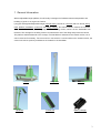
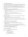
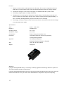
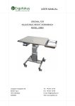
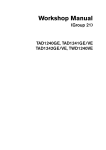
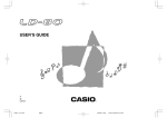
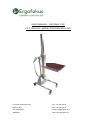
USER MANUAL - ORIGINAL FOR
LIFT TROLLEY, MODEL DESIGNATION LD80
Ljunggren & daughters AB
Tel: +46 243 153 50
Backes väg 3
Fax: +46 243 153 59
784 54 Borlänge
E-mail: [email protected]
SWEDEN
Web: www.ergofokus.se
CONTENTS
1
GENERAL INFORMATION .....................................................................................................3
1.1 FUNCTION OF THE SYSTEM .......................................................................................................4
1.2 PRODUCT WARRANTY ..............................................................................................................4
2
PROHIBITIONS - WARNINGS - REQUIREMENTS ............................................................4
2.1 GENERAL INFORMATION............................................................................................................4
2.2 HAZARD NOTICES .....................................................................................................................5
2.3 USE OF THE MACHINE ...............................................................................................................5
2.4 MAINTENANCE AND REPAIR ......................................................................................................6
3
OPERATOR’S MANUAL ..........................................................................................................6
3.1 FUNCTION OF THE SYSTEM .......................................................................................................6
3.2 OPERATION ..............................................................................................................................7
3.3 SAFETY.....................................................................................................................................7
3.4 STARTING AND STOPPING .........................................................................................................7
3.5 PROBLEMS DURING OPERATION................................................................................................8
3.6 CONSUMABLE SUPPLIES ...........................................................................................................8
3.7 MAINTENANCE ..........................................................................................................................8
3.8 HANDLING OF THE USER MANUAL .............................................................................................8
4
ASSEMBLY – DISASSEMBLY - REPARATION ................................................................8
4.1 DISASSEMBLY OR SCRAPPING OF THE SYSTEM ............................................................................8
4.2. REPAIR AND SPARE PARTS .........................................................................................................9
4.3 TROUBLESHOOTING .....................................................................................................................9
5
PRODUCT SPECIFICATION ..................................................................................................9
BATTERY CHARGER – USER MANUAL................................................................................... 11
6
2
EC DECLARATION OF CONFORMITY FOR MACHINERY ............................................ 13
1 General Information
With its adjustable-height platform, this lift trolley is designed to facilitate internal transportation and
handling of goods in an ergonomic fashion.
Ljunggren & daughters’ adjustable-height LD80 lift trolley consists of a chassis with four wheels, lifting
mast, platform, handlebar, control unit and battery charger. The chassis section contains the controller
card, lift motor and battery. The lifting strap is inside the lifting column, which is in turn detachable from
the base. The carriage for the lifting column is located at the end of the lifting strap inside the column.
The platform shall be attached to the carriage. The handlebar is attached to the chassis section, but it
can be removed if necessary. The control unit is connected to a contact outlet on the chassis section; the
control unit with its up/down pushbuttons are located on the handlebar.
Chassis
Handlebar
Lifting mast
Control Unit
Platform
Battery Charger
3
1.1 Function of the System
·
The main switch can be turned on “1” or turned off “0” while the battery is being charged.
·
The main switch must be turn on “1” while the lift trolley is being used.
·
The main switch must be turned off “0” when the lift trolley is not being used.
·
The platform can be either raised or lowered by means of the control unit.
Ø The “UP” button will raise the platform until the button is released or once the platform has
reached its highest level and the electronic circuit is broken.
Ø The “DOWN” button tells the lift motor to allow the platform to fall. The platform thus lowers
solely by its own weight.
·
All four wheels are pivoted, which allows the trolley to be steered easily in all directions.
·
Two of the wheels can be locked in braking mode.
·
With the wheels locked, loading is made easier and safer.
·
The lift trolley is operated solely by battery.
·
The battery is charged using the included charger, which is connected to the provided socket in
the bottom section and then to a mains supply of 230 volts. The charger contact must be
disconnected when not plugged into a 230-volt power source.
1.2 Product Warranty
Ljunggren & daughters’ lift trolley is covered by a warranty against manufacturing defects for a period of
12 months following the date of manufacture.
Ljunggren & daughters’ warranties will only be honoured provided that the lift trolley has been used in the
manner intended and as long as it has not be disassembled or subjected to any kind of tampering.
2 Prohibitions - Warnings - Requirements
2.1 General Information
-
The main switch can be turned on “1” or turned off “0” while the battery is being charged.
-
The main switch must be turned on “1” when the lift trolley is to be used.
-
The main switch must be turned off “0” when the lift trolley is not being used.
-
The charger must only be connected to outlets of the same voltage indicated on its rating plate.
-
The lift trolley may only be used as an adjustable-height trolley for the internal transport of goods
-
The lift trolley must not used for continuous and sustained raising and lowering. Excess loads cause
the controller card to interrupt operation. Between lifts, during movement, the system is given the
downtime it requires.
-
Maximum load on the lift trolley is 80 kg.
-
It must be used and stored indoors.
-
When necessary, the lift trolley can be lifted by the bottom section by two people. For greater
stability, first lower the platform to its lowest level. Grab hold of the trolley near the wheel brackets in
order to lift it. It is not possible to lift the lift trolley by the platform. The platform would move upward.
-
4
This operating manual must always be available when needed.
2.2 Hazard Notices
-
Keep your hands away from the lifting column when raising or lowering. Failure to observe this risks a
finger being pinched at the guide rollers for the lifting column’s carriage. There is also a risk that a
hand or finger could be pinched where the lifting strap enters the top of the lifting column.
-
Make sure that you do not have a foot or other part of your body under the platform as it is being
lowered. This risks crush injuries.
-
Keep in mind that loads might fall off the platform. Make sure that the platform is lowered when
transporting goods. Take hold of the handlebar with both hands when moving the trolley and push it
in front of you. Centre the load on the platform near the lifting column.
-
If the platform becomes caught against something nearby when being lowered and thus does not
continue downward, immediately raise the platform until it is free and then remove the object in the
way. NEVER attempt to remove the object while the platform is in contact with it.
-
The lift trolley may only be used on a flat, hard floor. Avoid using the trolley on inclined or slippery
surfaces. The goods on the platform might slide off! The trolley can roll away!
-
When working with the lifting trolley, do not place it against anything with a horizontal edge or under a
low space. When raising the lift, this may result in a hand or other part of the body being crushed
between the platform and this edge or low clearance.
-
The maximum load on the lift trolley must not be exceeded, statically or dynamically.
-
The batteries contain substances that are harmful to human health and to the environment. Never
tamper with the batteries.
2.3 Use of the Machine
The lift trolley may only be used as an adjustable-height trolley for the internal transport of goods.
The lift trolley must not be used as:
-
A lift for persons
-
A lifting jack
-
A clamping device
-
A counterstay
-
A pressing machine
-
A means of transporting goods that are hazardous to the environment or to human health.
-
The lifting trolley must not be used or stored in environments that would subject it to corrosion or to
mechanical, thermal or chemical damage or to strong electromagnetic fields.
N.B.! At all times when the platform is attached to the lift, the locking screw must be tightened in order to
prevent the platform from coming loose.
When using a platform of one’s own design, the maximum dimensions must not be exceeded: length –
max 500 mm, width – max 400 mm. The platform must be secured in place from the underside using 5
screws.
The lift trolley must not be used in environments that exceed the limits indicated in this operating manual.
5
2.4 Maintenance and Repair
-
Check periodically, approximately once per month given normal use, that the lifting strap does not
have damage that can result in breakage in the long term. Lower the platform to its lowest height.
-
If the lifting strap is defective in any way, the lift trolley must not be used until the strap has been
replaced with a new one.
-
Check to see whether anything has occurred which requires that corrective measures be taken inside
the lift trolley, for example, the batteries need to be replaced or the lifting strap needs to be repaired.
Lay the lift trolley down forward. The batteries are attached to the bottom plate of the bottom section.
Please note when detaching the bottom plate that it weighs 5 kg (with the batteries). Remove the six
screws holding the bottom plate in place. Disconnect the positive pole of the battery packet first; then
perform the desired measures.
-
Except for the batteries, no reparations to any electrical connections may be made.
-
No reparations may be made to the controller card or to the lift motor.
-
The battery pack contains a fuse on the lead between the batteries. It shall be rated at 30A.
-
Ljunggren & daughters’ product liability is only limited to products that were defective coming from the
factory. Ljunggren & daughters’ product liability will be disclaimed in part or in whole if the user does
not follow the care instructions or uses spare parts that are not original.
For each repair, there is a written set of instructions available in order to minimise the risk of error;
request such instructions when you order the spare parts and read them thoroughly before you begin
effecting repairs.
In order for a product warranty to be valid following a repair, the following conditions apply:
-
Only original parts may be used when making repairs.
-
No repairs may be made to electrical connections, the lift motor, battery, controller card, charger or
control unit.
-
Repairs shall be made according to the enclosed instructions.
-
Following the repair, the lift trolley must continue to be used only in accordance with the specified
data.
3 Operator’s Manual
3.1 Function of the System
Ljunggren & daughters’ adjustable-height lift trolley consists of a chassis with four wheels, lifting mast,
platform, handlebar, control unit and battery charger. The bottom section contains the controller card, lift
motor and battery. The lifting strap is inside the lifting column, which is in turn detachable from the base.
The carriage for the lifting column is located at the end of the lifting strap inside the column. The platform
shall be attached to the carriage. The handlebar is attached to the bottom section, but it can be detached
from this, as needed. The control unit is connected into its socket in the bottom section; the part with the
pushbuttons is attached to the handlebar.
All four wheels are pivoted, which allows the trolley easily to be steered in the direction the operator
wishes. Two of the wheels can also be locked in braking mode. With the wheels locked, loading is made
easier and safer.
The main switch on the lift trolley must be set to “1” during use.
6
When idle, the main switch on the lift trolley must be set to “0”.
The lift trolley is operated solely by battery. The battery is charged using the included charger, which is
connected to the provided socket in the chassis section and then to a mains supply of 230 volts. The
charger contact must be disconnected when not plugged into a 230-volt outlet. The lift trolley is not
intended for continuous and sustained raising and lowering.
3.2 Operation
The main switch can be turned on “1” or turned off “0” while the battery is being charged.
The main switch must be turned on “1” while the lift trolley is being used.
The main switch must be turned off “0” when the lift trolley is not being used.
The platform can be either raised or lowered by means of the two operating buttons on the control unit.
The “UP” button will raise the platform until the button is released or when the platform has reached its
highest level and the electronic circuit is broken. The “DOWN” button triggers the lift motor to allow the
platform to fall. The platform thus lowers solely by its own weight.
Set the brakes on all the wheels for safe loading and unloading.
When moving, release the brakes, take hold of the handlebar with both hands and push the trolley ahead
of you toward the desired location.
When necessary, the lift trolley can be lifted by the bottom section. For greater stability, first lower the
platform to its lowest level. Grab hold of the trolley near the wheel brackets in order to lift it. It is not
possible to lift the lift trolley by the platform, as this would only move the platform upward.
3.3 Safety
Keep your hands away from the lifting column when raising or lowering. Failure to observe this risks a
finger being pinched by the guide rollers for the lifting column’s carriage. There is also a risk that a hand
or finger could be pinched where the lifting strap enters the top of the lifting column.
Make sure that you do not have a foot or other part of your body under the platform as it is being
lowered. There is a risk of crush injuries.
Keep in mind that loads might fall off the platform. Make sure that the platform is lowered when
transporting goods.
The charger must only be connected to outlets of the same voltage indicated on its rating plate.
3.4 Starting and Stopping
Turn the main switch on the upper part of the chassis on to “1”.
Turn the main switch on the upper part of the chassis off to “0”.
It is only possible to move the platform while the up or down button is being held. If the platform is
overloaded or if it has reached its end position, the motion stops, even if the control button continues to
be depressed. For safety reasons, the button must first be released and then pressed again in order to
lower or raise the platform.
7
3.5 Problems during Operation
If any problems occur while raising or lowering the platform, immediately let go of the button on the
control panel. All movement will cease! Then carry out the necessary corrective measure. Refer then, if
necessary, to the “Troubleshooting” section further on in this user manual.
3.6 Consumable Supplies
The lift trolley contains no consumable parts. However, the battery, like all batteries, has a limited
lifetime. When the run-time following each charging is diminished, it is time to replace the battery.
3.7 Maintenance
The lift trolley should be fully charged prior to a protracted period of inactivity, such as a holiday.
The main switch can be turned on “1” or turned off “0” while the battery is being charged.
The main switch must be turned on “1” while the lift trolley is being used.
The main switch must be turned off “0” when the lift trolley is not being used.
The charger contact (24 volts) on the chassis should be disconnected when the 230-volt charger is not
connected to the mains.
The lift trolley’s battery can reverse polarity and remain unusable should it fail to be repeatedly
recharged for a protracted period or during an extended period of brief charging without the
charging being completed.
The lift trolley is maintenance-free given ordinary use and thus needs no servicing.
Normal cleaning shall be done using a mild cleaning agent (e.g., dish detergent or washer fluid such as
the kind used in cars). Powerful cleaning agents containing, for example, acids, ammonia or lye must not
be used.
The lift trolley can be cleaned in an upright position using water spray. Water must not be sprayed into
the location where the lift strap enters the top of the lifting column. Neither may water be sprayed in from
below through the draining holes in the bottom plate.
3.8 Handling of the User Manual
It is important that all those using the lift trolley read through and have access to this user manual.
4 Assembly – Disassembly - Reparation
4.1 Disassembly or Scrapping of the System
The positive pole on the battery pack must be disconnected before any work is done in the bottom unit,
regardless of whether it is assembly, disassembly, reparations or any other measure.
When scrapping the lift trolley, the battery, controller card, lift motor, charger and control unit must be
disposed of at a suitable destruction or waste management facility. The rest of the lift trolley consists of
fully recyclable and thereby environmentally friendly parts.
8
4.2. Repair and Spare Parts
The only repair measure available for the battery, lift motor, controller card, charger and control unit is
simply to replace the entire unit; they must not be taken apart. This is to prevent the risk of malfunction.
All these units are supplied as spare parts from Ljunggren & daughters or its representative.
For each repair, there is a written set of instructions available in order to minimise the risk of error;
request such instructions when you order the spare parts and read them thoroughly before you begin
effecting repairs.
State the designation from the product’s rating plate when ordering.
In order for a product warranty to be valid following a repair, the following conditions apply:
·
Only original parts may be used.
·
No repairs may be made to electrical connections, the lift motor, battery, controller card, charger or
control unit.
·
All repairs must be made according to the enclosed instructions.
·
The lift trolley may continue to be used only in accordance with the specified data.
4.3 Troubleshooting
The platform does not move when pressing either the up or down button. No weak clicking sound is
heard from the bottom section.
-
Make sure that the control unit is properly connected to the bottom section.
-
Make sure that the battery is charged by connecting the charger. See the user manual for the
charger.
-
The housing on the bottom plate feels hot. The overheating guard has broken. Allow the bottom unit
to cool.
-
None of the above help. Contact Ljunggren & daughters.
The platform moves upward for a short distance but then stops.
-
The platform has too heavy a load, thus tripping the safety switch. Reduce the load.
-
Charge the battery.
The platform moves slowly or not at all, in spite of a prolonged period of charging the battery.
-
Charge the battery. Alternatively, contact Ljunggren & daughters AB for a test of the battery status.
The platform does not move, no sound, either upward or downward.
-
Make sure that the main switch is turned on to “1”.
For any other faults, please contact Ljunggren & daughters AB.
5 Product Specification
Product:
Ljunggren & daughters adjustable-height lift trolley
Model:
Lift trolley: LD80.
Battery: 2 pcs CT8-12H-9ah
Controller card: Sepro type 3.4
Lift motor: MB080FG230.
Gear: NRMV040/18j=50/63B14.
9
Functional Principle of the System:
Battery operated, electronic control, lift motor with worm gear that winches the platform upward using a
lifting strap. When lowering, the lifting motor releases the strap.
Operating Conditions:
The lift trolley must not used for continuous and sustained raising and lowering. Excess loads cause the
controller card to interrupt operation. Between lifts, during transport, the system is given the downtime it
requires.
Capacity:
-
Upon a maximum load of 80 kg, the lift trolley can perform 10 lifts with 2 minutes of recovery time
between lifts.
-
For smaller loads, the lift trolley can perform more repetitive lifting with shorter recovery times.
-
The lift trolley is best charged after a work shift is completed in order to guarantee a fully charged
battery for the next shift.
-
The lift trolley can handle short periods of use in walk-in refrigerators and freezers.
-
Lifting capacity is reduced during protracted periods of use in cold areas.
Maximum Load:
Maximum permitted load on the platform is 80 kg. This load must not be exceeded.
Physical Dimensions:
Length
880 mm
Platform width
Width
420 mm
Maximum lifting height of platform
1400 mm
Height
1760 mm
Minimum lifting height of platform
165 mm
Length of platform
500 mm
Weight of lift trolley, approx.
400 mm
35 kg
Temperature Ranges:
Operation: 0 to +45 degrees C
Transport: – 20 to + 60 degrees C
After being transported at temperatures below 0 degrees C, the lift trolley must rest within the premises
at operating temperature for at least one hour prior to being used.
Electrical Supply:
Frequency: 50-60 Hz
Primary voltage: 230 V AC
Secondary voltage: 24 V DC
Secondary current fuse: 30 A
EMC Requirements:
Sources of interference with emissions of electromagnetic or electrical fields (for example, high-current
cables) that are stronger than what is allowed according to the applicable EMC directive must not be
located in the vicinity of the electrical parts of the lift trolley.
Suitable Fire Fighting:
Carbon dioxide, power-foam extinguishers or water mist. Do not use water streams.
Cleaning:
Normal cleaning shall be done using a mild cleaning agent (e.g., dish detergent or washer fluid such as
the kind used in cars). Powerful cleaning agents containing, for example, acids, ammonia or lye must not
be used.
10
The lift trolley can be cleaned in an upright position using water spray. Water must not be sprayed into
the location where the lift strap enters the top of the lifting column. Neither may water be sprayed in from
below through the draining holes in the bottom plate.
Environmental Considerations:
When scrapping the lift trolley, the battery, controller card, charger and control unit must be disposed of
at a suitable destruction or waste management facility. The rest of the lift trolley consists of fully
recyclable and thereby environmentally friendly parts.
Noise Level:
The noise level of the lift trolley does not exceed 70 dB (A).
NORDIC POWER 3-Stage Battery Charger – User Manual
Read this manual carefully and follow the instructions!
Introduction
A 3-stage charger with a constant load for maintenance charging of lead-acid batteries.
Cannot by overcharged and can be permanently connected.
Equipped with reverse-polarity and short-circuit protection.
The charger must be used indoors.
Panel Instructions
Three differently coloured LED lamps (green, yellow, red) indicate the charge status.
The red lamp lights when 80 % or less of the battery’s capacity remains.
The yellow lamp lights when 81-99% of the battery’s capacity remains.
The green lamp lights when the battery is 100% fully charged.
Safety
When charging, the battery must first be placed into the lift trolley, and then the contact is plugged into
the electrical outlet.
Once the battery has finished charging, the contact is unplugged from the electrical outlet, and then the
charger is removed from the lift trolley.
The charger contact (24 volts) must be disconnected from the chassis when the 230-volt charger is not
connected to the mains.
Do not charge a frozen battery: wait a few hours until the battery has reached room temperature.
The battery emits a small quantity of so-called oxyhydrogen gas. Avoid charging in the presence of
sparks.
Charging of the lift trolley must be done in a well-ventilated area.
The battery charger cannot overcharge the battery.
Do not expose the charger to water or moisture.
Keep the charger out of the reach of children.
11
Function
1. Place the contact with the cable upward on the lift trolley. The contact is magnetic and it turns
itself into the correct position if the contact is pressed toward the poles in the wrong direction.
2. Connect the charge to a 230 V AC power supply in a suitable wall outlet / power socket.
3. The battery charger begins to charge the battery.
4. Charging time is 2-8 hours given normal use of the lift trolley. If the lift trolley is used less or if
there is a lighter load, the battery charges more quickly, charging time being approximately 1-2
hours. A heavily discharged battery requires more than 8 hours to charge.
5. The charger contact (24 volts) must be disconnected from the chassis when the 230-volt charger
is not connected to the mains.
Specification
AC in
230V +- 10%, 50Hz
Efficiency
Normally 83%
Charging current
24 V 1.3 A
Absorption voltage
27.6 V DC
Construction
Plastic casing with ventilator slots.
Protection
Overcharge protection, short-circuit protection,
reverse-polarity protection.
Approved
CE: EN61010, EN61204,
EN50082, EN61000, EN55011, EN60555
Size
106 x 45 x 65 mm (LxWxH)
Weight
266 grams
Warranty:
Ljunggren & daughters’ lift trolley is covered by a warranty against manufacturing defects for a period of
12 months following the date of manufacture.
Ljunggren & daughters’ warranties will only be honoured provided that the lift trolley has been used in the
manner intended and as long as it has not be disassembled or subjected to any kind of tampering.
12
6 EC Declaration of Conformity for Machinery
Ljunggren & daughters AB
Backes väg 3
784 54 Borlänge
Sweden
Declares under its sole liability that the industrial kitchen trolley designated as:
Lift trolley
Model LD80
Serial number_____________________
Conforms to all the applicable provisions set out in the “Essential Health and Safety Requirements
Relating to the Design and Construction of Machinery “according to the European Parliament’s and
Council’s Directive 2006/42/EC, which is published in the Official Journal of the European Union.
Technical documentation is the responsibility of:
Björn Bok
Ljunggren & daughters AB
Backes väg 3
784 54 Borlänge
Sweden
Borlänge, on _____________________
Sara Ljunggren
13