1
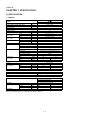
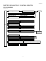
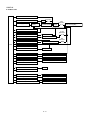
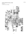
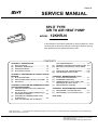
12KHR-N TopPage SERVICE MANUAL SPLIT TYPE AIR TO AIR HEAT PUMP MODEL 12KHR-N In the interests of user-safety (Required by safety regulations in some countries) the set should be restored to its original condition and only parts identical to those specified should be used. CONTENTS CHAPTER 1. SPECIFICATION [1] SPECIFICATION............................................ 1-1 [2] EXTERNAL DIMENSION............................... 1-2 [3] WIRING DIAGRAM........................................ 1-3 [4] ELECTRICAL PARTS .................................... 1-3 CHAPTER 2. EXPLAMATION OF CIRCUIT AND OPERATION [1] BLOCK DIAGRAMS....................................... 2-1 [2] MICROCOMPUTER CONTROL SYSTEM ........ 2-3 [3] FUNCTION .................................................... 2-9 CHAPTER 3. FUNCTION AND OPERATION OF PROTECTIVE PROCEDURES [1] PROTECTION DEVICE FUNCTIONS AND OPERATIONS................................................ 3-1 [2] AIR TO AIR HEAT PUMP OPERATION IN THERMISTOR ERROR ................................. 3-3 [3] THERMISTOR TEMPERATURE CHARACTERISTICS ............................................... 3-5 [4] HOW TO OPERATE THE OUTDOOR [5] [6] [7] [8] UNIT INDEPENDENTLY ............................... 3-6 GENERAL TROUBLESHOOTING CHART ........ 3-6 MALFUNCTION (PARTS) CHECK METHOD ................................................................. 3-8 OUTDOOR UNIT CHECK METHOD .......... 3-10 TROUBLESHOOTING GUIDE .................... 3-14 CHAPTER 4. REFRIGERATION CYCLE [1] FLOW FOW REFRIGERANT ........................ 4-1 [2] STANDARD CONDITION.............................. 4-1 [3] TEMPERATURE AT EACH PART AND PRESSURE IN 3-WAY VALVE ...................... 4-1 [4] PERFORMANCE CURVES........................... 4-2 CHAPTER 5. DISASSEMBLING PROCEDURE [1] DISASSEMBLY OF INDOOR UNIT............... 5-1 [2] DISASSEMBLY OF OUTDOOR UNIT......... 5-10 Parts Guide Parts marked with " " are important for maintaining the safety of the set. Be sure to replace these parts with specified ones for maintaining the safety and performance of the set. This document has been published to be used for after sales service only. The contents are subject to change without notice. 12KHR-N 5GTXKEG/CPWCN 12KHR-N CHAPTER 1. SPECIFICATION [1] SPECIFICATION 1. 12KHR-N MODEL ITEMS Rated cooling capacity (Min– Max.) Rated heating capacity (Min–Max.) Moisture removal (at cooling) Electrical data Phase Rated frequency Rated voltage Cool Rated current ڏ Heat (Min - Max.) Cool Rated input ڏ Heat (Min - Max.) Cool Power factor ڏ Heat Maximum operating current Compressor Type Model Oil charge Refrigerant system Evaporator Condenser Control Refrigerant (R410A) De-lce system Noise level High (at cooling) Low Soft Fan system Drive Air flow quantity High (at cooling) Low Soft Fan Connections Refrigerant coupling Refrigerant tube size Gas, Liquid Drain piping mm Others Safety device Air filters Net dimensions Net weight Width Height Depth kW kW Liters/h Hz V A A W W % % A dB(A) dB(A) dB(A) m3/min. m3/min. m3/min. INDOOR UNIT OUTDOOR UNIT 12KHR-N 3.5 (0.9 - 4.0) 4.6 (0.9 - 6.5) 1.2 Single 50 220-240 4.2 (0.9 - 5.7 ) 5.0( 0.9 - 7.4 ) 920 (200- 1250) 1075 (160 - 1700) 95 92 9.6 Hermetically sealed rotary type DA111A1F22F 450cc (Ester oil VG74) Louver Fin and Grooved tube type Corrugate Fin and Grooved tube type Expansion valve 1180g Micro computer controled reversed systems 40 47 – – 27 – Direct drive 9.3 32.2 7.6 – 5.2 – Cross flow fan Propeller fan Flare type 3/8", 1/4" O.D I16 mm mm mm kg Compressor: Thermal protector Fan motors: Thermal fuse Fuse, Micro computer control Polypropylene net (Washable) 790 780 260 540 290 265 11 36 NOTE: The conditions of star”✩” marked item are based on ‘EN14511’. 1–1 12KHR-N [2] EXTERNAL DIMENSION 1. Indoor unit 㧔Unit㧦㨙㨙㧕 260 290 798 18.5 58 175 INVERTER AIR CONDITIONER 22.0 2. Outdoor unit 540 72 299 324 135 12 37.5 4. 5 58 14 265 81 136 540 780 165 167.5 1–2 12KHR-N [3] WIRING DIAGRAM 1. Indoor unit W I R I N G D I A G R A M ޛ%% ޜINVERTER AIR-CONDITIONER $%0 $%0 $%0 %0 % &$ 04 %0 %0 %0 %0 %0 5'4+#. 5+)0#. %+4%7+6 0( %0 % (75' 219'45722.; 70+6 %0 ' %0 %0 $-$.#%- $4$4190 9*9*+6' 1414#0)' 4&4'& ) ;)4''0;'..19 % ) ; / %.756' 4 )'0'4#61 4 (#0/1614 9* ̪%#76+10*+)*81.6#)' / 4& (7 8 # % %0 .178'4 8'46+%#..'(6 5 UNIT TO UNIT CORD %0 554 $%0 2#0'. 59+6%* 2#0'. 59+6%* .'(6 2#0'. / 4+)*6 2#0'. / .'(6 / *114+)*6 / *11FLASH CONNECTOR %0 6* 14 %0 %0 %0 / / .178'4 2+2'6'/2.178'4 6*'4/+5614 8'46+%#.4+)*6 *14+<106#. %0 $%0 6* 5'0514$1#4& 70+6 ) ; 411/6'/2 6*'4/+5614 2. Outdoor unit CC632 [4] ELECTRICAL PARTS 1. Indoor unit DESCRIPTION Indoor fan motor Indoor fan motor capacitor Transformer FUSE1 MODEL MLB395 – – – REMARKS DC motor – – QFS-GA078JBZZ (250V, 3.15A) MODEL DA111A1F22F MLB078 – – – – – – REMARKS DC motor DC motor – QFS-GA064JBZZ(250V, 1A) QFS-GA051JBZZ(250V, 2A) QFS-GA052JBZZ(250V, 3.15A) QFS-CA001JBZZ(250V, 20A) QFS-CA002JBZZ(250V, 15A) 2. Outdoor Unit DESCRIPTION Compressor Outdoor fan motor Outdoor fan motor capacitor Fu4 Fu3 Fu2 Fu1 Fu5, 6 6'4/+0#. $1#4& ˴$4 㧔$-㧕 %10641.$1#4&70+6 %0 +06'4%100'%6+10 ˴$1#4&70+6 4'%'+8'4 $%0 $1#4&70+6 #7: 59 176&11470+6 6'4/+0#. $1#4& $%0 &+52.#; $%0 $1#4&70+6 $%0 %0 %0 %0 +0&11470+6 1–3 LED INDICATION FOR SELF-DIAGNOSIS Blinking NO. #DPQTOCN%QPVGPVU Short circuit of the outdoor thermistor Overheat of the compressor Open circuit of the outdoor thermistor DC over current AbnormalAC current Abnormal wire connection Abnormal thermistor of four way valve EEPROM error of outdoor unit Abnormal outdoor fan motor Thermal fuse error of outdoor unit Abnormal compressor rotation Abnormal PAM voltage and clock signal Open circuit of serial signal line Short circuit of serial signal line Abnormal fan motor of indoor unit EEPROM error of indoor unit <Indication of the abnormal condition> LED indicator will blink, if the set is in abnormal condition. 12KHR-N CHAPTER 2. EXPLAMATION OF CIRCUIT5GTXKEG/CPWCN AND OPERATION 12KHR-N [1] BLOCK DIAGRAMS 1. Indoor unit DC power supply circuit Rectification circuit AC power 3.15A Fuse Fan motor PWM control circuit Indoor fan motor Rotation pulse input circuit Fan motor pulse detect AC clock circuit Remote controller signal reception circuit Wireless remote control operation Buzzer drive circuit Audible operation confirmation CPU reset circuit CPU CPU oscillator circuit Room temp. detect circuit Room temp. thermistor Heat exchanger pipe thermo circuit Heat exchanger pipe thermistor EEPROM Louvre angle, fan speed Select circuit Wireless, preheat, Model select Serial I/O circuit Indoor/outdoor control signal I/O Unit-unit wiring (AC power and serial signals) Auto restart circuit Test run circuit Test run (forced operation) Auxiliary mode Auxiliary mode button ON/OFF Power on circuit Self diagnostics, fault diagnosis Cluster generator drive circuit Cluster generator Louver motor drive circuit (Horizontal) How direction control (Horizontal louver motor) Louver motor drive circuit (Vertical, right) How direction control (Vertical louver motor,right) Louver motor drive circuit (Vertical, left) How direction control (Vertical louver motor,left) LED Drive circuit LED display 2–1 12KHR-N 2. Outdoor unit AC clock circuit 15A protection Pulse amplitube modulation circuit IGBT Power supply circuit Power factor converter circuit Smoothing circuit Filter circuit 20A protection CPU oscillator circuit 3.15A protection DC overvoltage detection circuit Outdoor fan drive circuit Outdoor fan 4-way valve relay drive circuit 4-way valve 15A protection DC overcurrent detection circuit Power transistor module drive circuit CPU Power transistor module Serial I/O circuit CPU reset circuit Position detection circuit Compressor AC overcurrent detection circuit Current transformer Compressor thermo circuit Compressor thermistor Heat exchanger pipe thermo circuit Heat exchanger pipe thermistor Outdoor temp. thermo. circuit Outdoor temperature thermistor EEPROM LED drive circuit LED Test mode circuit Expansion valve drive circuit Expansion valve Suction temp. thermo. circuit Suction pipe thermistor 2-way valve temp. thermo. circuit 2-way valve thermistor Terminal board, Terminal fuse, circuit Terminal board, Terminal fuse 2–2 Unit-unit wiring (AC power and serial signals) 1 1 1 CN604 BCN603 CN14 THERMISTOR PIPE TEMP TH2 THERMISTOR ROOM TEMP TH1 3 4 5 HANG M L 5 5 2 4 4 3 3 6 1 8 8 2 CN605 7 8 8 1 6 5 7 7 5 6 4 4 2 1 3 7 R64 3.3K R61 3.3K 3 2 1 6 BCN10 2 2 R136 56K Q3 KRA106S 2 9 9 5V 3 4 5 HANG M R CN11 CN10 5V R54 10KF R51 2.7K CN15 R120 6.8KF 1 2 CN606 BCN604 R52 1.5K R53 10KF R50 100K R48 100K 3 1 1 3 3 4 4 R74 2M R73 1K 4 5 6 PANEL M L 2 2 PC8 IC3 KIA431 C31 0.1uF 50V R118 6.8KF R119 10.0KF 5 5 R49 220 6 7 7 1 2 CN607 8 8 R71 1M 1 2 3 4 5 6 7 8 3 14 9 10 11 12 1 2 3 4 5 6 5V 5V 10K R129 R122 R124 R123 R128 1K 5V 10K 10K 10K C62 10V 100uF CN17 1 2 3 4 5 6 JP2 8 7 6 5 4 C61 0.1uF 25V R107 4.7K D18 JP1 R105 4.7K C60 4.7uF 25V 4 3 2 1 CN90 5V D5 D1FL20U D10 RU2CV1 R43 47 CN13 R137 5V 1K R106 1K 1K R104 R102 C19 100uF 50V ZD3 HZ27-2 3 LOUVER M H 1 470 2 R91 R92 HAJP C59 100uF 10V 25V 0.1uF C58 5.1K 10K 8MHz OSC1 10K 680 AUTO RESTART SELECT POWER MODEL 4 5 5V R44 10 6 Q10 100 CN14 KRC 106S R99 R98 81 82 83 84 85 86 87 88 89 90 91 92 93 94 95 96 97 98 99 JP8 R114 10KF 10KF R112 C24 47uF 16V R45 3.3 R46 220 PC8 PC817x3 R89 2.2M 1 M C D 47K R117 4.3KF R113 R72 6.8K 1 2 4 4 R76 1K 2 R75 1K 3 IC1 P120 P47 P46 P45 P44 P43 P42 P41 P40 REST P124 P123 FLMD X2 X1 REGC VSS VSS0 VDD VDD0 S 8 7 6 5 PC7 R63 680 3 4 Q2 680 R35 KRA224S R41 R40 1/2W 1MX2 C25 0.01uF 50V 2 PC817XP3 1 C22 0.1uF 50V CONTROL S S S C20 120uF 450V 1 3 4 2 D2SBA60 DB1 C12A 275V 0.1uF KIA7815 1K 1K R134 R132 PC6 PC817XP3 PC5 PC817XP3 IC5 NTC1 10D R135 4.7K 3 4 2 1 R36 R37 56K R33 6.8K 1/2W 1M 8.2K 50V 0.01uF C47 1uF C56 10V 25V 0.1uF 0.1uF 0.01uF 25V 25V 50V 0.1uF C53 C54 C55 C68 50V C48 0.01uF C49 1000p 0.1uF C50 0.1uF C51 0.1uF C52 50V 1000pF 50V 25V 25V 25V C40 5 8 6 IC7 7 8 KID65004AF 9 9 1 2 KID65004AF IC8 CN15 8 3 4 5 9 6 8 7 IC9 8 CN19 KID65004AF 1 9 2 3 8 IC14 4 BZ1 50 49 48 47 46 45 44 43 42 41 40 39 38 37 36 35 34 33 32 31 5 1 NC NC NC NC 2 9 12V 2 1 9 10 11 3 KRC108S Q15 5 R82 KRC106S Q11 5V 1 2 3 5 7 Vm E 1 2 1 2 10K 1 2 1 2 Vs PG Vcc C8 0.01uF 250Vx2 GND CN3 G(Y) 0.1uF 275V C13 25V 0.1uF CN609 CN608 47K JPW R81 R80 R79 WIRELESS 47K R116 4.7Kx2 4 5V 3 4 9 10 11 BCN604 PC4 PC81716NIP 5V CN15 1/4W 1.8K C14 50V 0.01uF CN16 KID65004AF AVR0 P111 P110 AVR1 P10 P11 P12 P13 P14 P15 P16 P17 P57 P56 P55 P54 P53 P52 P51 P50 IC13 8 9 10KF R57 12V R133 4.7K 6.8K 200K 1/2W 13 4 5 6 PANEL M R FLASH VDD TXD0 RXD0 FLMD0 TOOL1 TOOL0 RESET GND D8 D1FL20U R70 10K C23 10uF 16V C30 220uF 10V 6 PC817XP3 C29 1000uF 25V R38 R28 39K D4 IC2 TOP258PN KRC108S Q13 R97 4.7K KRC108S Q14 PANEL SW2 PANEL SW1 DC FAN MOTOR C7 C6 IC12 IC11 12V 12V PR32MA11NXPF SSR1 12V R17 3.3K R87 1.5M R111 19V 3.3K NC R42 120K 1/2W NC R29 R31 C21 1000pF 1KV NC R26 R27 D1N60 275V 0.1uF C12 NR1 10K 1/4W 910x2 R18 3 R19 2 R101 4.7K TR1 R100 4.7K 5V ZD1 HZ24-2 BLUE 5V R127 10K R83 10K SERIAL SIGNAL CIRCUIT 1W 100K R16 C5 15 BCN602 4.7K CN18 CN17 1 1 3 4 2 CN603 3 2 1 6 7 8 9 3 2 1 6 7 8 9 9 10 11 12 13 9 10 11 12 13 4 4 6 7 6 7 8 9 10 8 9 10 CN601 8 9 10 7 7 BCN601 6 6 9 5 5 PC1 R401 PC2 PC853HXP BCN301 BCN302 10 8 5 5 4 3 3 3 4 2 3 1 2 2 2 1 1 1 5 3 4 2 B BK BR 47 R301 47 + R318 180 1W 2 1 3 4 RD WH R315 100 1W 1W 180 1W 560 1W 180 1W 180 R310 1W 180 BLUE PC 1/4W 3.6Kx2 1W 560 R303 LED310 IC301 IC401 R302 R316 100 1W R309 R308 R307 R306 R305 R304 2 N 1 TERMINAL BOARD 3P R317 360 1W + S C SW401 SAFETY SW R1 2W 3.3K A PC817XP3 BCN401 8 5 1 3.15A-250V 2 3 4 D1N60 D1 FU1 1 4 CN602 5V 4 1 7 12V 1 5 2 6 CN1 CN1 8 BCN602 R7 100K 7 C1 35V100uF C16 35V 100u 250V 0.01u C2 35V0.047uF CLUSTER CLUSTER 16 R94 1K 10K R121 C67 50V 1000p R110 4.7K C17 25V 0.1u C66 C65 25V 0.1uF 25V 0.1uF C3 50V0.01uF D7 S3L20U TEST 47K R95 R77 4.7K R90 7.5K R78 4.7K JP9 47K R96 R109 C18 50V 0.1u R34 3.3K NC NF1 C15 R6 4.7K 275V 0.1uF C12B 1K D2 R8 R9 D1N60 11K 2W 11K 2W 200K 1/2W R86 1K R84 R85 R10 R11 16V47uF 1000p 50V 0.1uF 25V 0.1uF 25V 47K 47K 0.1uF 0.1uF 0.1uF R108 10K 10K R93 100K KID65004AF R32 KID65004AF 80 79 78 77 76 75 74 73 72 71 70 69 68 67 66 65 64 63 62 61 60 59 58 57 56 55 54 53 52 51 P140 P141 P142 P143 P144 P145 P00 P01 P02 P03 P04 P131 P130 P20 P21 P22 P23 P24 P25 P26 P27 P150 P151 P152 P153 P154 P155 P156 P157 AVSS C46 C45 C44 R125 R88 C43 C42 C41 25V 25V 25V P60 P61 P62 P63 P31 P64 P65 P66 P67 P77 P76 P75 P74 P73 P72 P71 P70 P06 P05 VSS1 P80 P81 P82 P83 P84 P85 P86 P87 P30 VDD1 1 2 NC 3 4 5 6 7 8 9 10 11 12 13 14 15 16 17 18 19 20 21 22 23 24 25 26 27 28 29 30 R39 100K C90 RED OPERATION LED 301 KID65783AF 16V 47uF C402 56K 2.7K C401 25V 0.1uF C301 25V 0.1uF 12V 1W 560 16V 47uF C302 YELLOW TIMER LED 302 GREEN FULL POWER LED 303 GREEN OUTDOOR TEMP 2–3 LED 304 5V 14 3 16 c1 b1 COM1 a1 b1 c1 d1 e1 f1 15 g1 13 a1 d1 2 1 e1 f1 4 g1 9 7 e2 12 a2 g2 d2 6 f2 5 c2 11 b2 COM2 a2 b2 c2 d2 e2 f2 10 SG301 g2 8 12KHR-N [2] MICROCOMPUTER CONTROL SYSTEM 1. Indoor unit 1.1. Electronic control circuit diagram CN18 CN17 6 7 8 9 10 CN601 5 6 7 8 9 10 BCN601 5 6 7 8 9 10 5 4 3 2 R401 BCN301 BCN302 10 9 8 7 6 5 4 3 2 1 9 4 1 8 8 9 3 13 13 7 7 4 12 12 6 5 6 5 3 11 11 12V 1 1 2 10 10 2 2 2 9 9 3 3 1 8 8 CN602 1 7 7 BCN602 CN603 1 2 2 1 3 3 BCN401 47 R301 16V 47uF C402 47 + R318 180 1W R315 100 1W R309 R308 R307 R306 R305 R304 R310 1W 220 1W 220 1W 620 1W 220 1W 220 1W 620 R303 1/4W 7.5Kx2 BLUE PC LED310 IC301 IC401 R302 R316 100 1W + SW401 SAFETY SW R317 360 1W 16V 47uF C302 4 LED 301 C301 25V 0.1uF YELLOW TIMER LED 302 RED OPERATION C401 25V 0.1uF LED 303 GREEN FULL POWER LED 304 4 1W 620 2–4 GREEN OUTDOOR TEMP 5V 14 3 16 c1 b1 COM1 a1 b1 c1 d1 e1 f1 15 g1 d1 2 1 e1 f1 13 a1 4 g1 9 7 e2 g2 d2 6 f2 5 c2 11 b2 COM2 a2 b2 c2 d2 e2 f2 10 SG301 12 a2 g2 8 12KHR-N 1.2. Display circuit diagram 12KHR-N 1.3. Printed wiring board For 2KHN model main PWB From cluster unit From fan motor From horizontal louver motor To vertical louver motor(left) To vertical louver motor(right) From sensor PWB For 2KHN model sensor PWB To main PWB 2–5 From pipe thermistor (relay connector) 12KHR-N For 2KHN model connection PWB From hang motor left From panel motor left From panel SW left To main PWB From display PWB(black) To main PWB From display PWB(yellow) To main PWB For 2KHN model display PWB To connection PWB 2–6 From panel SW right To main PWB From panel motor right From hang motor right 㧮㧸㨁㧱 㧾㧝㧡 㧾㧝㧢 㧝㧚㧢 㧝㧚㧢 㧯㧞㧥 㧢㧟㧜㨂 㧜㧚㧝Ǵ 㧜㨂 㧯㧣㧤 㧝㧜㨂 㧠㧣Ǵ 㧾㧤㧠 㧥㧚㧡㧟㧷㧲 㧰㧡 㧞㨃 㧝㧷 㧟 㧝 㧽㧝 㧞 㧟 㧞 㨀㧾㧝 㧤 㧝㧜 㧝㧝 㧢 㧡 㧥 㧣 㧰㧣 㧰㧢 㧰㧝㧠 㧾 㧯㧟㧟 㧡㧜㨂 㧝Ǵ 㧗 㧜㨂 㧾㧝㧠㧠 㧢㧚㧤㧷 㧽㧥 㧷㧾㧯㧝㧜㧡㧿 㧡㨂 㧜㨂 㧯㧣㧣 㧜㧚㧜㧝Ǵ 㧾㧤㧡 㧢㧚㧤㧷 㧜㨂 㧾㧤㧝 㧝㧜㧷 㧢 㧡 㧠 㧟 㧞 㧝 㧠㧚㧣㧷 㨎 㧜㨂 㧤 㧾㧞㧡 㧝㧚㧢㧡㧷㧲 㧯㧞㧟 㧜㧚㧝Ǵ 㧾㧞㧣 㧢㧤 㧝㨃 㧾㧞㧠 㧞㧞㧷 㧝㧡㨂 㧡㨂 㧝㧞㨂 㧜ǡ 㧜ǡ 㧺 㧾㧝㧝㧢 㧝㧷 㧺㧾㧞 㧾㨅㧝 㧯㧞㧢 㧾㧞㧤 㧞㧣㧡㨂 㧝㧛㧞㨃 㧜㧚㧜㧟㧟Ǵ 㧝㧞㧜 㧝 㧟 㧡㨂 㧾㧝㧞㧠 㧝㧷 㧝 㧠 㧤 㧞 㧟 㧜㨂 㧾㧝㧡㧝 㧞㧜㧜㧷㧲 㧾㧝㧡㧜 㧾 㧞㧜㧜㧷㧲 㧡㨂 㧶㧼㧢 㧾㧝㧠㧟 㧞㧜㧷㧲 㧶㧼㧡 㧾㧝㧞㧜 㧞㧜㧷㧲 㨅 㨆 㧜㨂 㧝㧢 㧝㧡 㧝㧠 㧝㧟 㧝㧞 㨎 㨍 㨃 㧯㧥㧟 㧜㧚㧝Ǵ 㧜㨂 㧾㧝㧟㧜 㧝㧜㧷 㧯㧞㧞 㧜㧚㧝Ǵ 㧤 㧜㨂 㧝 㧣 㧢 㧟 㧞 㧡 㧠 㧵㧯㧢 㧠 㧟 㧞 㧝 㧯㧺㧱 㧔㧱㧱㧼㧾㧻㧹˴㧯㧵㧾㧯㨁㧵㨀㧕 㧟 㧠 㧝 㧡㨂 㧥 㧜㨂 㧝㧝 㧝㧜 㧵 㧯㧝㧞㧡 㧜㧚㧝Ǵ 㧹 㧵㧯㧝 㨏 㧟 㧝㧜 㧥 㧤 㧣 㧢 㧝㧝 㧡 㧠 㧯㧢㧟 㧡㧜㨂 㧟㧟㧜㧼 㧰㧞㧟 㧤 㧣 㧢 㧡 㧠 㧟 㧞 㧝 㧢㧞 㧢㧝 㧢㧜 㧡㧥 㧡㧤 㧡㧣 㧡㧢 㧼㧠㧝 㧼㧠㧜 㧼㧟㧣 㧼㧟㧢 㧯 㨂㧯㧯 㧔㨆㧕 㧼㧟㧡 㧡㧠 㧡㧟 㧡㧞 㧔㨅㧕 㧼㧟㧟 㧔㨂㧕 㧼㧟㧞 㧔㨄㧕 㧼㧟㧝 㧾㧟㧟 㧞㧚㧞㧷 㧾㧟㧝 㧝㧷 㧾㧟㧞 㧝㧜㧷 㧜㨂 㧯㧟㧢 㧯㧟㧡 㧯㧟㧠 㧝㧜㧜㧜㧼㧟 㨏 㧡㧡 㧢㧟 㧼㧠㧞 㧔㨃㧕 㧼㧟㧠 㧢㧠 㧼㧠㧟 㧜㨂 㧠㧝 㧠㧞 㧠㧟 㧠㧠 㧠㧡 㧠㧢 㧠㧣 㧠㧤 㧠㧥 㧡㧜 㧡㧝 㧾㧟㧜 㧠㧚㧣㧷 㧾㧡㧥˴㧝㧜㧜 㧾㧡㧤˴㧝㧜㧜 㧾㧡㧣˴㧝㧜㧜 㧯㧢㧞 㧯㧢㧝 㧡㧜㨂 㧡㧜㨂 㧟㧟㧜㧼 㧟㧟㧜㧼 㧰㧞㧠 㨆㧰㧟 㧾㧡㧜 㧝㧚㧤㧷 㧞㧜 㨃 㨂 㧾㧟㧤˴㧝㧷 㨁 㧾㧟㧣˴㧝㧷 㧾㧟㧢˴㧝㧷 㧯㧥㧤 㧜㧚㧝Ǵ 㧯㧥㧡 㧜㧚㧝Ǵ 㧡㨂 㧯㧥㧠 㧝㧜㨂 㧝㧜㧜Ǵ 㧟 㧞 㧠 㧾㧝㧡㧠 㧝㧜㧷 㧡㨂 㧔㧯㧺㧕 㧠 㧟 㧞 㧝 㧲㧸㧭㧿㧴 㧜㨂 㧸㧱㧰㧝 㧥 㧤 㧣 㧢 㧡 㧠 㧟 㧞 㧝 㧯㧺㧰 㧲㧯㧠 㧜㨂 㧰㧝㧝 㧡㨂 㧯㧠㧠 㧝㧜㧜㧜㧼 㧯㧠㧟 㧝㧜㧜㧜㧼 㧯㧠㧞 㧝㧜㧜㧜㧼 㧯㧠㧝 㧝㧜㧜㧜㧼 㨃 㧯㧠㧜 㧝㧜㧜㧜㧼 㧯㧠㧡 㧜㧚㧜㧝Ǵ 㧯㧠㧣 㧝㧜㧜Ǵ 㧝㧜㨂 㧜㨂 㧯㧟㧣 㧞㧡㨂 㧟㧟㧜Ǵ 㧿 㧯㧡㧠 㧝㧜㧜Ǵ 㧞㧡㨂 㧰㧝㧜 㧯㧡㧞 㧝㧜㧜Ǵ 㧞㧡㨂 㧰㧥 㧯㧡㧜 㧝㧜㧜Ǵ 㧞㧡㨂 㧝㧞㨂 㧡㨂 㧜㨂 㨀㧴㧝 㧞 㨂㨁㧲㧮 㧵㧼㧹 㧔㧞㧙㨃㧭㨅˴㨂㧭㧸㨂㧱㧕 㨀㧴㧡 㧔㧿㨁㧯㨀㧵㧻㧺㧕 㨀㧴㧠 㧔㧻㨁㨀㧰㧻㧻㧾˴㨀㧱㧹㧼㧕 㨀㧴㧟 㧔㧴㧱㧭㨀㧙㧱㨄㧕 㨀㧴㧞 㧔㧯㧻㧹㧼㧾㧱㧿㧿㧻㧾㧕 㧯㧡㧡 㧜㧚㧝Ǵ 㧯㧡㧟 㧜㧚㧝Ǵ 㨂㧼㧵 㨁㧼 㨂㨂㧲㧮 㨂㧼 㨂㨃㧲㧮 㧝㧝 㧝㧜 㧝㧟 㧣 㧝㧣 㧝㧠 㧝㧢 㧲㧜 㨂㧺㧯 㨃㧺 㨂㧺 㨁㧺 㨂㧺㧵 㨃㧼 㨂㧼㧯 㧞㧝 㨂㨃㧲㧿 㧠 㧢 㧞㧞 㨂㨂㧲㧿 㧤 㧡 㧟 㧝㧞 㧯㧡㧝 㧜㧚㧝Ǵ 㧯㧠㧥 㧜㧚㧝Ǵ 㧞㧟 㨂㨁㧲㧿 㧾㧠㧣㧘㧠㧣㧭 㧝㧛㧠㨃 㧟㧟㧞 㧾㧠㧤㧘㧠㧤㧭 㧝㧛㧠㨃 㧟㧟㧞 㧰㧤 㧯㧺㧤 㧝㧜 㧝 㧞 㧟 㧠 㧡 㧢 㧣 㧤 㧥 㨀㨔㨑˴㨟㨕㨓㨚˴㨛㨒˴㨑㨍㨏㨔˴㨜㨛㨣㨑㨞˴㨟㨡㨜㨜㨘㨥 㨑㨤㨜㨞㨑㨟㨟㨑㨟˴㨠㨔㨑˴㨒㨛㨘㨘㨛㨣㨕㨚㨓˴㨢㨛㨘㨠㨍㨓㨑㧚 㧝㧡㨂 㧾 㧡㨂 㨀㧴㧱㧾㧹㧵㧿㨀㧻㧾 㧔㧰㧯˴㧻㨂㧱㧾˴㧯㨁㧾㧾㧱㧺㨀˴㧵㧺㧿㧼㧱㧯㨀˴㧯㧵㧾㧯㨁㧵㨀㧕 㧜㨂 㧡㨂 㨆 㨅 㨄 㨂 㧯㧟㧥 㧝㧜㧜㧜㧼 㧾㧠㧡 㧯㧠㧤 㧝㧜㧷 㧜㧚㧝Ǵ 㧾㧠㧢 㧝㧷 㨁 㨆㧰㧠 㧯㧟㧤 㧜㧚㧝Ǵ 㧔㧵㧼㧹˴㧰㧾㧵㨂㧱˴㧯㧵㧾㧯㨁㧵㨀㧕 㧝㧡㨂 㧯 㧾㧢㧤㨪㧣㧞 㧢㧚㧤㧷㧲㧡 㧝㧜㧷㧡˴˴㧾㧢㧟㨪㧢㧣 㧜㧚㧜㧝Ǵ㧡˴˴㧯㧢㧡㨪㧢㧥 㧯㧠㧢 㧝㧜㧜㧜㧼 㧾㧝㧟㧟˴㧝㧜㧜 㧾㧝㧟㧞˴㧝㧜㧜 㧾㧝㧟㧣˴㧝㧜㧜 㧾㧝㧟㧠˴㧝㧜㧜 㧾㧝㧟㧡˴㧝㧜㧜 㧾㧝㧟㧢˴㧝㧜㧜 㧲㧯㧟 㧔㨀㧴㧱㧾㧹㧵㧿㨀㧻㧾˴㧯㧵㧾㧯㨁㧵㨀㧕 㨀㧣 㧾㧱㧰 㨀㧤 㨃㧴㧵㨀㧱 㨀㧥 㧻㧾㧭㧺㧳㧱 㧔㧸㧱㧰˴㧯㧵㧾㧯㨁㧵㨀㧕 㧾㧣㧟 㧞㧚㧞㧷 㧾 㧿 㨀 㧽 㧞㧞 㧞㧝 㧞㧟 㧾㧡㧢 㧞㧜㧚㧡㧷㧲 㧾㧡㧡 㧞㧜㧚㧡㧷㧲 㧾㧡㧠 㧞㧜㧚㧡㧷㧲 㧰㧱㧮㨁㧳 㧝 㧯㧺㧙㧞 㧹㧻㧺㧵㨀㧻㧾 㧾㧝㧡㧡㧝㧜㧷 㧜㨂 㨅 㧾㧠㧥 㧡㨃 㧜㧚㧜㧞 㧺 㨆 㧼㧿㧞㧝㧥㧢㧠㧙㧯 㧾㧡㧝㨪㧡㧟 㧝㧛㧞㨃 㧠㧣㧜㧷㧲㧟 㧾㧝㧝㧞 㧝㧡㧷 㧾㧥㧥˴㧝㧜㧜 㧯㧝㧞㧞 㧝㧜㧜㧜㧼 㧯㧵㧺 㧝㧡 㧵㧼㧹 㧞㧠 㧾㧝㧝㧟 㧯㧤㧢 㧯㧢㧜 㧔㧯㧻㧹㧼˴㧼㧻㧿㧵㨀㧵㧻㧺˴㧵㧺㧿㧼㧱㧯㨀˴㧯㧵㧾㧯㨁㧵㨀㧕 㧝㧥㧚㧝㧷㧲 㧜㧚㧝Ǵ 㧞㧡㨂 㧜㧚㧝Ǵ 㧯㧢㧠 㧞㧡㨂 㧜㧚㧝Ǵ 㧰㧞㧝 㧰㧞㧞 㧜㨂 㧝㧡㨂㧔㧼㧭㧹˴㧯㧵㧾㧯㨁㧵㨀㧕 㧝 㧵㧯㧤 㧷㧵㧭㧟㧟㧥 㧝㧞 㧝㧠 㧝㧟 㧞 㧾㧝㧝㧠 㧝㧹 㧜㨂㧙㧼 㧹 㧼 㧲㨁㧡 㧞㧡㧜㨂 㧝㧡㧭 㧾㧝㧞㧡 㧯㧝㧠 㧝㧛㧞㨃 㧞㧣㧜㧷㧲 㧢㧟㧜㨂 㧾㧝㧞㧢 㧜㧚㧟㧟Ǵ 㧝㧛㧞㨃 㧞㧣㧜㧷㧲 㧾㧝㧞㧤 㧾㧢 㧾㧝㧞㧣 㧝㧟㧷㧲 㧞㧟㧚㧣㧷㧲 㧝㧟㧷㧲 㧽㧣 㧾㧞㧜㧜 㧷㧾㧯㧝㧜㧡㧿 㧝㧷 㧡㨂 㧜㨂 㨖 㧾㧞 㧝㧛㧞㨃 㧞㧡㧡㧷㧲 㧾㧡 㧝㧛㧞㨃 㧟㧜㧜㧷㧲 㧾㧣 㧞㧟㧚㧣㧷㧲 㧠㧞㧜㨂 㧣㧡㧜Ǵ 㧞 㧾㧝㧜㧣 㧟㧟㧜 㧾㧝㧝㧝 㧼㧯㧠 㧞㧚㧞㧷 㧼㧯㧤㧝㧣㨄㧼㧟 㧾㧝㧝㧜 㧝㧡㧜 㧰㧞㧜 㧺 㧜㨂 㧡㨂 㧯㧥㧞 㧜㧚㧜㧝Ǵ 㧾㧝㧞㧥 㧝㧜㧷 㧔㧵㧺㨂㧱㧾㨀㧱㧾˴㧯㨁㧾㧾㧱㧺㨀˴㧵㧺㧿㧼㧱㧯㨀˴㧯㧵㧾㧯㨁㧵㨀㧕 㧵㧯㧥 㧝㧡㨂 㧾㧝㧞㧟 㧝㧜㧜㧷㧲 㧯㧥㧜 㧝㧜㧜㧜㧼 㧯㧤㧥 㧜㧚㧝Ǵ 㧵 㧰㧝㧤 㧜㨂 㨔 㧼㧜㧡 㧔㨃㧕 㧯㧤㧤 㧝㧜㧜㧜㧼 㨂 㧯㧟㧜 㧝㧜㨂 㧝㧜㧜Ǵ 㨁 㧠㧞㧜㨂 㧣㧡㧜Ǵ ˴˴㧗㧯㧥 ˴˴㧗㧯㧝㧜 㧝㧤㨂㧙㧼 㧡㨂 㧽㧡 㧟㧟 㧟㧠 㧟㧡 㧟㧢 㧟㧣 㧟㧤 㧟㧥 㧠㧜 㧼㧜㧠 㧔㨅㧕 㧼㧜㧢 㧼㧜㧟 㧟㧞 㧟㧝 㧔㧻㧕 㧔㧮㧕 㧟㧜 㧼㧜㧞 㧼㧜㧝 㧼㧜㧜 㧰㧮㧞 㧰㧮㧝 㧝㧥 㧝㧤 㧝㧣 㧞㧥 㧞㧤 㧞㧣 㧠㧙㨃㧭㨅 㨂㧭㧸㨂 㧯㧻㧵㧸 㧯㧺㧠 㧔㧠㨃㧭㨅˴㨂㧭㧸㨂㧱˴㧰㧾㧵㨂㧱˴㧯㧵㧾㧯㨁㧵㨀㧕˴ 㨐 㨑 㨄㧝 㨂㧿㧿 㨄㧜 㧞㧢 㧞㧡 㧞㧠 㧹㧰㧞 㧹㧰㧝 㧾㧿㨀 㧿 㧾㧥㧞 㧜ǡ 㧡㨂 㧯㧤㧟 㧝㧜㧜㧜㧼 㧾㧝㧜㧢 㧟㧚㧟㧷 㧡㨂 㧞㧟 㧞㧞 㧞㧝 㧞㧜 㧯㧤㧞 㧜㧚㧜㧝Ǵ㧜㨂 㧽 㨀 㧮㨀㧡 㧲㨁㧢 㧞㧡㧜㨂 㧝㧡㧭 㧳㧾 㧯㧣㧥 㧯㧥㧣 㧝㧜㨂 㧞㧞㧜Ǵ 㧜㧚㧜㧝Ǵ 㧷㧾㧯㧝㧜㧞㧿 㧽㧢 㧜㨂 㧾㧥㧜 㧝㧚㧜㧷㧲 㧔㧻㨂㧱㧾˴㨂㧻㧸㨀㧭㧳㧱˴㧵㧺㧿㧼㧱㧯㨀˴㧯㧵㧾㧯㨁㧵㨀㧕 㧜㨂 㧳㧾 㧸㧡 㧾㧥㧝 㧾㧝㧠㧣 㧰㧞 㧢㧚㧠㧥㧷㧲 㧝㧜㧷 㧾㧝㧜㧡 㧞㧞㧷 㧡㨂 㧻㧿㧯㧝˴㧠㧹㧴㨦 㧾㧥㧟 㧾㧥㧠 㧜㨂 㧵㧯㧠 㧣㧤㧜㧡 㧾㧟㧠㧝㧜㧷 㧾㧟㧡㧝㧜㧷 㧶㧼㧝㧢 㧡㨂 㧜㨂 㧡㨂 㧜㨂㧙㧼 㧝㧤㨂㧙㧼 㧾㧞㧢 㧠㧚㧢㧠㧷㧲 㧠 㨐 㨑 㧹㧾㨅㧝 㧻㨁㨀 㧼㨀㧯 㧼㧯㧤㧝㧣㧝㧢㧺㧵㧼 㧝 㧯㧤㧝 㧟 㧜㧚㧜㧝Ǵ㧞 㧼㧯㧟 㧾㧝㧠㧢 㧝㧜㧜㧷 㧾㧝㧜㧝㧘㧝㧜㧞 㧝㧛㧞㨃˴㧠㧣㧷㧞 㧾㧝㧜㧟㧘㧝㧜㧠 㧝㨃˴㧠㧣㧷㧞 㧵㧯㧟 㧯㧤㧡 㧜㧚㧝Ǵ 㧵㧯㧣 㧷㧵㧰㧢㧡㧜㧜㧠㧭㧼 㧜㨂 㧥 㧝㧚㧜㨗㧲 㧲㨁㧞 㧞㧡㧜㨂 㧟㧚㧝㧡㧭 㧜㨂 㧳㧾 㧾㧝㧜㧞 㧾㧤㧥 㧾㧞㧟 㧯㧞㧝 㧢㧤㧷 㧜㧚㧜㧟㧟Ǵ 㧾㧞㧝 㧝㧚㧡㧷 㧝㧞㨂 㧾㧤㧞 㧝㧜㧷 㧹㧾㨅㧝 㧯㧣㧢 㧝㧜㧜㧜㧼 㧾㨅㧝 㧝㧞㨂 㧯㧺㧝㧞 㧱㨄㧼㧭㧺㧿㧵㧻㧺˴ 㨂㧭㧸㨂㧱˴㧯㧻㧵㧸 㧽㧝㧜 㧷㧾㧭㧝㧜㧢㧿 㧝㧡㨂 㧾㧤㧜 㧝㧜㧜㧷 㧡㨂 㨍 㧾㧞㧞 㧝㧜㧷 㧯㧤㧠 㧾㧤㧣 㧟㧡㨂 㧝㧡㧜Ǵ 㧝㧜㧷 㧯㧝㧥 㧟㧡㨂 㧝㧡㧜Ǵ 㧯㧞㧜 㧞㧡㨂 㧢㧤㧜Ǵ 㧾㧤㧤 㧡㧝㧜㧷 㧝㧛㧠㨃 㧯㧣㧡 㧝㧜㧜㧜㧼 㧾㧣㧠 㧠㧚㧣㧷 㧡㨂 㧾㧣㧢 㧾㧣㧡 㧡㧢㧷 㧞㧚㧣㧷 㧟 㧼㧯㧞 㧼㧯㧤㧡㧟㧴㨄㧼 㧝 㧼㧯㧝 㧼㧯㧤㧝㧣㨄㧼㧟 㧠 㧝 㧠 㧠 㧔㧿㧱㧾㧵㧭㧸˴㧯㧵㧾㧯㨁㧵㨀㧕 㧞㨃 㧝㧷 㧞 㧔㧿㨃㧵㧯㧴㧵㧺㧳˴㧯㧵㧾㧯㨁㧵㨀㧕 㧾㧞㧥 㧯㧝㧤 㧢㧤㧜㧼 㧰㧠 㧾㧝㧥 㧞㧷 㧯㧝㧡 㧾㧝㧣 㧡㧜㨂 㧞㨃 㧝㧜Ǵ 㧝㧜 㧾㧝㧤 㧰㧟 㧝㧚㧡㧷 㧜㨂 㧞㨃 㧝㧷 㧔㧲㧭㧺˴㧹㧻㨀㧻㧾˴㧰㧾㧵㨂㧱˴㧯㧵㧾㧯㨁㧵㨀㧕 㧜㨂 㧾㧤㧢 㧢㧚㧤㧷㧶 㧾㧤㧟 㧝㧜㧷 㧡㨂 㧾㧣㧣 㧞㧣㧜 㧾㧠 㧟㧚㧟㧷 㧯㧝㧟 㧰㧝㧜㧚㧝Ǵ 㧺㧾㧝 㧠 㧞㧡㧜㨂 㧠㧣㧜㧜㨜㧲 㧯㧠 㧯㧠㧭 㧾㧠㧜 㧾㧠㧝 㧾㧠㧞 㧯㧝㧢 㧟㧟㧜㧜㧼 㧰㧝㧡 㧶㧼㧱 㧯㧟㧞 㧜㧚㧝Ǵ 㧜㨂 㧟 㧵㧯㧡 㧿㧙㧤㧜㧤㧠㧞㧯㧺㨅 㧾㧣㧥 㧝 㧝㧜㧜 㧞 㧡㨂 㧔㧲㧭㧺˴㧹㧻㨀㧻㧾㧕 㧯㧺㧟 㨖 㧯㧟㧝 㧜㧚㧝Ǵ 㧲㨁㧟 㧞㧡㧜㨂 㧞㧭 㧝 㧞 㧟 㧠 㧡 㧣 㧯㧝㧞㧠 㧜㧚㧝Ǵ 㧾㧣㧤 㧞㧣㧜 㧔㧾㧱㧿㧱㨀˴㧯㧵㧾㧯㨁㧵㨀㧕 㧜㨂 㧯㧝㧣 㧠㧣㧜㧼 㧾㧝㧠 㧢㧤㧜 㨆㧰㧝 㧾㧞㧜 㧟㧚㧟㧷 㧞 㧿㧭㧝 㧯㧝㧞 㧞㧡㧜㨂 㧠㧣㧜㧜㧼 㧞㧿㧭㧝㧡㧤㧢㧳 㧜㨂 㧯㧥㧝 㧜㧚㧝Ǵ 㧯㧞㧣 㧝㧷㨂 㧞㧞㧜㧼㧲 㧞 㧿㨛㨡㨞㨏㨑 㧳㧺㧰 㧻㧯㧼㧛㧲㧮 㧢 㧣 㧝㧜 㧥 㧤 㧝˴㨪˴㧠 㨂㨏㨏 㧰㨞㨍㨕㨚 㧵㧯㧞 㧿㨀㧾㧙㧸㧠㧣㧞 㨔 㧡㧜㨂 㧜㧚㧝Ǵ 㧡㨂 㧲㧮 㧮㨀㧟 㧝 㧲㧯㧡 㧯㧺㧝㧜 㧮㧸㨁㧱 㧾㧱㧰 㧲㨁㧝 㧞㧡㧜㨂 㧞㧜㧭 㧯㧡 㧯㧡㧭 㧞㧡㧜㨂 㧠㧣㧜㧜㨜㧲 㧞㧡㧜㨂 㧠㧣㧜㧜㨜㧲 㧯㧣 㧯㧣㧭 㧮㨀㧝 㧮㧾㧻㨃㧺 㨅㧱㧸㧸㧻㨃 㧛㧳㧾㧱㧱㧺㧮㨀㧠 㧲㨁㧠 㧝㧭 㧞㧡㧜㨂 㧾㧤 㧝㧛㧞㨃˴㧝㧹 㧾㧥 㧝㧛㧞㨃˴㧡㧝㧜㧷 㨖 㧝㧜㧞͠ 㨀㨔㨑㨞㨙㨍㨘 㨒㨡㨟㨑 㧞 㧝 㧯㧢 㧯㧢㧭 㧞㧡㧜㨂 㧠㧣㧜㧜㨜㧲 㧝 㧯㧞 㧰㧝㧟 㧾㧝㧜㧝 㧯㧝 㧵㧺 㧾㧝㧜㧠 㧮㨀㧢 㧰㧝㧞 㧾㧝㧜㧟 㧯㨀㧝 㧹㧰㧜 㧼㧜㧣 㧞㧣㧡㨂 㧝Ǵ㧲 㧼㧢㧟 㧼㧝㧜 㧾㧠㧟 㧡㧝㧜㧷 㧝㧛㧠㨃 㧯㧟 㧼㧢㧞 㧼㧝㧝 㧟 㧼㧢㧝 㧼㧝㧞 㧸㧠 㧾㧢㧞 㧝㧚㧤㧷 㧼㧢㧜 㧝 㧾㧢㧜 㧝㧚㧤㧷 㧭㨂㧾 㧞㧣㧡㨂 㧝Ǵ㧲 㧾㧢㧝 㧝㧚㧤㧷 㧭㨂㧿㧿 㧼㧝㧟 㧟 㧼㧡㧢 㧸㧟 㧭㨂㧯㧯 㧼㧝㧢 㧝 㧶㧼㧞 㧿㧱㨀 㧞㧣㧡㨂 㧝Ǵ㧲 㧼㧡㧡 㧼㧞㧝 㧝㧛㧞㨃 㧝㧹 㧾㧝 㧼㧡㧠 㧼㧞㧞 㧮㨀㧞 㧼㧡㧟 㧼㧞㧟 㧮㧸㨁㧱 㧼㧡㧝 㧼㧞㧡 㧔㨁㧕 㧺 㧼㧡㧜 㧼㧞㧢 㧔㨂㧕 㧺 㧼㧠㧢 㧼㧞㧣 㧔㨃㧕 㨀㧱㧾㧹㧵㧺㧭㧸 㧮㧻㧭㧾㧰 㧼㧻㨃㧱㧾 㧿㨁㧼㧼㧸㨅 㧶㧼㧲 㧼㧝㧠 㧶㧼㧝 㧼㧡㧞 㧼㧞㧠 㧲˴㧻㨁㨀 㧼㧝㧡 㧿㧱㨀 㧼㧠㧡 㨂㧿㧿 㧾㧝㧝㧡 㧝㧚㧤㧷 㧼㧡㧣 㧼㧝㧣 㧼㧠㧠 㧼㧟㧜 㧔㨁㧕 2–7 㧼㧞㧜 㧯㧝㧝㧭 㧯㧝㧝 㧞㧡㧜㨂 㧠㧣㧜㧜㨜㧲 -*40176&114˴㧯㧵㧾㧯㨁㧵㨀˴㧰㧵㧭㧳㧾㧭㧹 12KHR-N 2. Outdoor unit 2.1. Electronic control circuit diagram 12KHR-N 2.2. Printed wiring board To Terminal Board (2) (Red) To Control Box (Green/Yellow) To Terminal Board (N)(Blue) To Terminal Board (1) (Brown) From 4 Way Valve From Expansion Valve From Thermistor From Terminal Board To Reactor (Gray) From Fan Motor From Compressor (R) (Orange) To Reactor (Gray) From Compressor (C) (White) From Compressor (S) (Red) 2–8 12KHR-N [3] FUNCTION 1. Function 1.1. Restart control 1.5. Indoor unit overheat prevention control Once the compressor stops operating, it will not restart for 180 seconds to protect the compressor. During heating operation, if the temperature of the indoor unit heat exchanger exceeds the indoor unit heat exchanger overheat prevention temperature (about 45 to 54qC) which is determined by the operating frequency and operating status, the operating frequency is decreased by about 4 to 15 Hz. Then, this operation is repeated every 60 seconds until the temperature of the indoor unit heat exchanger drops below the overheat protection temperature. Therefore, if the operating compressor is shut down from the remote control and then turned back on immediately after, the compressor will restart after a preset delay time. (The indoor unit will restart operation immediately after the ON switch is operated on the remote control.) Once the temperature of the indoor unit heat exchanger drops below the overheat protection temperature, the operating frequency is increased by about 4 to 10 Hz every 60 seconds until the normal operation condition resumes. Compressor operation Compressor ON Compressor can turn ON Compressor remains OFF for 180 seconds OFF operation on remote control ON operation on remote control If the temperature of the indoor unit heat exchanger exceeds the overheat protection temperature for 60 seconds at minimum operating frequency, the compressor stops operating and then restarts after about 180 seconds, and the abovementioned control is repeated. Compressor ON 1.6. Outdoor unit overheat prevention control During cooling operation, if the temperature of the outdoor unit heat exchanger exceeds the outdoor unit heat exchanger overheat prevention temperature (about 55qC), the operating frequency is decreased by about 4 to 15 Hz. Then, this operation is repeated every 60 seconds until the temperature of the outdoor unit heat exchanger drops to about 54qC or lower. 1.2. Cold air prevention control When the air to air heat pump starts up in heating mode, the indoor unit fan will not operate until the temperature of the indoor unit heat exchanger reaches about 23qC in order to prevent cold air from blowing into the room. Also, the indoor unit fan operates at low speed until the temperature of the indoor unit heat exchanger reaches about 38qC so that people in the room will not feel chilly air flow. Once the temperature of the outdoor unit heat exchanger drops to about 54qC or lower, the operating frequency is increased by about 4 to 10 Hz every 60 seconds until the normal operation condition resumes. Indoor unit heat exchanger temperature If the temperature of the outdoor unit heat exchanger exceeds the outdoor unit heat exchanger overheat protection temperature for (120 sec : outdoor temperature t 40qC x 60 sec : outdoor temperature < 40qC) at minimum operating frequency, the compressor stops operating and then restarts after about 180 seconds, and the abovementioned control is repeated. Set fan speed 38 35 Indoor unit fan at low speed 23 1.7. Compressor overheat prevention control 21 Indoor unit fan in non-operation If the temperature of the compressor exceeds the compressor overheat prevention temperature (110qC), the operation frequency is decreased by about 4 to 10 Hz. Then, this operation is repeated every 60 seconds until the temperature of the compressor drops below the overheat protection temperature (100qC). 1.3. Indoor unit heat exchanger freeze prevention control If the temperature of the indoor unit heat exchanger remains below 0qC for 4 consecutive minutes during cooling or dehumidifying operation, the compressor operation stops temporarily in order to prevent freezing. Once the temperature of the compressor drops below the overheat protection temperature, the operating frequency is increased by about 4 to 10 Hz every 60 seconds until the normal operation condition resumes. When the temperature of the indoor unit heat exchanger rises to 2qC or higher after about 180 seconds, the compressor restarts and resumes normal operation. If the temperature of the compressor exceeds the overheat protection temperature (for 120 seconds in cooling operation or 60 seconds in heating operation) at minimum operating frequency, the compressor stops operating and then restarts after about 180 seconds, and the abovementioned control is repeated. 1.4. Outdoor unit 2-way valve freeze prevention control If the temperature of the outdoor unit 2-way valve remains below 0qC for 10 consecutive minutes during cooling or dehumidifying operation, the compressor operation stops temporarily in order to prevent freezing. 1.8. Startup control When the air to air heat pump starts in the cooling or heating mode, if the room temperature is 2qC higher than the set temperature (in cooling operation) or 3.5qC lower (in heating operation), the air to air heat pump operates with the operating frequency at maximum. Then, when the set temperature is reached, the air to air heat pump operates at the operating frequency determined by fuzzy logic calculation, then enters the normal control mode after a while. When the temperature of the 2-way valve rises to 10qC or higher after about 180 seconds, the compressor restarts and resumes normal operation. 2–9 12KHR-N 1.9. Peak control 1.14. Power ON start If the current flowing in the air to air heat pump exceeds the peak control current the operation frequency is decreased until the current value drops below the peak control current regardless of the frequency control demand issued from the indoor unit based on the room temperature. If a jumper cable is inserted in the location marked with HAJP on the indoor unit control printed circuit board (control PCB), connecting the power cord to an AC outlet starts the air to air heat pump in either cooling or heating mode, which is determined automatically by the room temperature sensor. 1.10. Outdoor unit fan delay control When a circuit breaker is used to control the ON/OFF operation, please insert a jumper as described above. The compressor stops immediately after cooling, dehumidifying or heating operation is shut down, but the outdoor unit fan continues operation for 50 seconds before it stops. 1.15. Self-diagnostic malfunction code display 1.15.1 Indoor unit 1.11. Defrosting 1) When a malfunction is confirmed, a flashing malfunction code number is displayed to indicate the type of malfunction. 1.11.1 Reverse defrosting When the air to air heat pump is in non-operating condition, holding down AUX button for more than 5 seconds activates the malfunction code display function. The defrost operation starts when the compressor operating time exceeds 20 minutes during heating operation, as shown below, and the outside air temperature and the outdoor unit heat exchanger temperature meet certain conditions. When the defrost operation starts, the indoor unit fan stops. The defrost operation stops when the outdoor unit heat exchanger temperature rises to about 13qC or higher or the defrosting time exceeds 10 minutes. 20 min or more Start of heating operation 20 min or more The operation continues only in the case of a serial open-circuit, and the main relay turns off after 30 seconds if the open-circuit condition remains. In the case of a serial short-circuit, the air to air heat pump continues operating without a malfunction code display. 20 min or more The malfunction information is stored in memory, and can be recalled later and shown on display. 2) The self-diagnostic memory can be recalled and shown on the display by stopping the operation and holding down AUX button for more than 5 seconds. Defrosting Max. 10 min Defrosting Max. 10 min 3) The content of self-diagnosis (malfunction mode) is indicated by a flashing number. (For details, refer to the troubleshooting section.) 1.12. ON timer The ON timer can be activated by pressing the ON timer button. When the ON timer is activated, the operation start time is adjusted based on fuzzy logic calculations 1 hour before the set time so that the room temperature reaches the set temperature at the set time. 1.15.2 Outdoor unit If a malfunction occurs, LED1 on the outdoor unit flashes in 0.2-second intervals as shown below. (Example) Compressor high temperature abnormality 1.13. OFF timer ON The OFF timer can be activated by pressing the OFF timer button. When the OFF timer is set, the operation stops after the set time. OFF 1 sec 1 sec 0.6 sec When this timer is set, the compressor operating frequency lowers for quieter operation, and the room temperature is gradually varied after one hour (reduced 1qC three times (max. 3qC) in heating, or increased 0.3qC three times (max. 1qC) in cooling or dehumidifying operation) so that the room temperature remains suitable for comfortable sleeping. 1.16. Information about auto mode In the AUTO mode, the temperature setting and mode are automatically selected according to the room temperature and outdoor temperature when the unit is turned on. Heating operation Set temperature Modes and Temperature Settings O -1 C O -1 C O -1 C Activation of OFF timer 1 hour later Timer setting Max. Max. 1.5 hours 2 hours reached later later Cooling/dehumidifying operation O O Set temperature Activation of OFF timer 0.3 C 0.3 C 1 hour later the figures in ( ) are temperature settings During operation, if the outdoor temperature changes, the temperature settings will automatically slide as shown in the chart. O 0.3 C Max. Max. Timer setting 1.5 hours 2 hours reached later later 2 – 10 12KHR-N 1.17. Adjusting the air flow direction 1.17.2 Horizontal air flow direction 1.17.1 Vertical air flow direction 1 the HORIZONTAL AIR FLOW button to set the desired air flow direction 1 Press Press the VERTICAL AIR FLOW button to set the desired air flow direction. 1 1 AUTO mode AUTO obliquely downward HEAT mode AUTO obliquely downward downward CAUTION: Never attempt to adjust the open panel and the louvres manually. • Manual adjustment of the open panel and the louvres can cause the unit to malfunction. COOL/DRY mode AUTO obliquely upward obliquely downward TIPS ABOUT AIR FLOW DIRECTION “AUTO“ COOL mode 10 minutes later The open panel will be set obliquely downward for 10 minutes, and then shift to obliquely upward to deliver cool air to the ceiling. HEAT mode The open panel will be set obliquely backward when outlet air temperature is low, and then shift to obliquely downward when outlet air becomes warm. When outlet air temperature is low DRY mode The open panel will be set obliquely upward. 2 – 11 When outlet air becomes warm 12KHR-N 1.18. Difference of operation in Auto and Manual modes In the Auto mode, the temperature setting is automatically determined based on the outside air temperature. In addition, the air to air heat pump operation differs from the operation in the Manual mode as explained below. 1.18.1 Difference relating to set temperature Temperature setting method Auto mode Cooling Heating Dehumidifying Automatic temperature setting based on outside air temperature. Can be changed within r2qC using remote control. Manual mode Heating Can be changed between 18 and 32qC using remote control. Cooling Can be changed between 18 and 32qC using remote control. 1.19. Dehumidifying operation control ZONE If the room temperature is 26qC or higher when dehumidifying operation starts, the dehumidifying operation provides a low cooling effect in accordance with the room temperature setting automatically determined based on the outside air operation. (The setting value is the same as the set temperature for cooling operation in the auto mode.) Dehumidifying Automatic setting. Can be changed within r2qC. COMPRESSOR Hot keep (When room temperature reaches setting temperature) If the room temperature is lower than 26qC when dehumidifying operation starts, the dehumidifying operation minimizes the lowering of the room temperature. FAN AUTO OFF SOFT LOW HIGH Ultra soft (Lower than Fan speed “soft”) Keep the setting 1.20. Self Clean operation Heating or Fan operation and Cluster operation are performed simultaneously. O 0.6 C The judgment of whether Heating or Fan operation is used is based on the outside air temperature at 3 minutes after the start of internal cleaning. Set temperature 1.23. Winter cool The operation stops after 40 minutes. (The air to air heat pump shows the remaining minutes: 40 o 39 o 38 ... 3 o 2 o 1) Heating operation Cooling operation is available during the winter season by the built in winter cool function. Fan operation O 24 C Lower limit of outdoor temperature range is -10qC DB. When the outside air temperature is low, the outdoor unit fan operates at slower speed. Outside air temperature 1.21. Plasmacluster Ion function NOTE: Built-in protect device may work when outdoor temperature falls below 21qC DB., depending on conditions. The Plasmacluster lon generator inside the air conditioner will release positive and negative plasmacluster ions into the room. Approximately the same numbers of positive and negative ions released into the air will reduce some airborne mold. 1.24. 10qC OPERATION Heating operation with 10qC set temperature will be performed. 1) Press the MODE button of Remote controller and select HEAT mode. During operation, press the PLASMACLUSTER button. • The remote control will display “ • The blue PLASMACLUSTER lamp on the unit will light up. “. 2) Press the ON / OFF button to start HEAT operation. 3) Press the 10qC button. TO CANCEL • Press the PLASMACLUSTER button again. • Use of the PLASMACLUSTER operation will be memorized, and it will be activated the next time you turn on the air conditioner. • To turn off the PLASMACLUSTER lamp, press the DISPLAY button. • To perform the PLASMACLUSTER operation in FAN only mode, press the PLASMACLUSTER button while the unit is not operating. The mode symbol of the remote control will go off and the fan speed can not be set to AUTO. The remote control will display 10qC. TO CANCEL The PLASMACLUSTER lamp on the unit will turn off. NOTE: • Hot keep zone ٕ Press the 10qC button again. • 10qC operation will also be cancelled when the operation mode is changed, or when the unit is turned off. NOTE: • 10qC operation will not be available with heating operation automatically selected by AUTO mode. 1.25. Auto restart 1.22. Hot keep When power failure occures, after power is recovered, the unit will automatically restart in the same setting which were active before the power failure. If the room temperature is in the Hot keep zone during heating, the compressor is turned off to prevent overheating. 1.25.1 Operating mode (Cool, Heat, Dry) 2 – 12 • Temperature adjustment (within 2qC range) automatic operation • Temperature setting • Fan setting • Air flow direction 12KHR-N • Power ON/OFF • Full power setting • Automatic operation mode setting • Internal cleaning • Swing louvre 1.25.3 Disabling auto restart function • Plasmacluster mode By removing (cutting) jumper 8 (JP8) on the printed circuit board (PCB), the auto restart function can be disabled. 1.25.2 Setting not memorized • Timer setting 2. Explanation of cluster circuit The cluster unit generates cluster ions, which are circulated throughout the room by the air flow created by the blower fan (indoor unit fan motor) in the air to air heat pump unit. 1) When microcomputer output turns "H," the IC13 output changes to "Lo," turning ON the SSR1 and applying 100 V to the cluster unit for the generation of cluster ions (positive and negative ions). 12V AC230V IC13 R17 R19 SSR1 Microcomputer output Cluster unit R16 R18 C5 5 4 1 1 6 4 2 1 3. Outline of PAM circuit 3.1. PAM (Pulse Amplitude Modulation) The PAM circuit varies the compressor drive voltage and controls the rotation speed of the compressor. The IGBT shown in the block diagram charges the energy (electromotive force) generated by the reactor to the electrolytic capacitor for the inverter by turning ON and OFF. Reactor L5 DB1 AC 230V Noise filter + IPM Compressor DB2 IGBT drive circuit AC clock detection circuit Overvoltage detection circuit IGBT Compressor position detector [PAM drive circuit] Microcomputer (IC1) PAM drive circuit block diagram When the IGBT is ON, an electric current flows to the IGBT via the reactor (L5) and diode bridge (DB2). When the IGBT turns OFF, the energy stored while the IGBT was ON is charged to the voltage doubler capacitor via the diode bridge (DB1). As such, by varying the ON/OFF duty of the IGBT, the output voltage is varied. 2 – 13 12KHR-N DB1 Reactor Stored energy L5 DB2 IGBT ON IGBT OFF IGBT 3.2. High power factor control circuit This circuit brings the operating current waveform closer to the waveform of commercial power supply voltage to maintain a high power factor. Because of the capacitor input, when the PAM circuit is OFF, the phase of the current waveform deviates from the voltage waveform as shown below. To prevent this deviation, a current is supplied during the periods indicated by "O" in the diagram. To determine the length of period to supply a current, the zero-cross timing of the AC input voltage is input to the microcomputer via the clock circuit. The power source frequency is also determined at the same time. The IGBT turns ON after the time length determined by the zero-cross point to supply a current to the IGBT via the reactor. This brings the current waveform closer to the voltage waveform in phase. As described above, the ON/OFF operation of the IGBT controls the increase/decrease of the compressor power supply voltage (DC voltage) to improve the compressor efficiency and maintain a high power factor by keeping the current phase closer to that of the supply voltage. AC voltage waveform AC voltage waveform AC current waveform AC current waveform Zero-cross detection IGBT ON period AC voltage and current waveforms when PAM is OFF AC voltage and current waveform when PAM is ON 3.2.1 Detailed explanation of PAM drive circuit sequence AC voltage waveform Clock 50Hz A A 1.2mS B 1.0mS C 0.25 2.3mS IGBT ON B C 3.2.2 AC clock (zero-cross) judgment • The clock circuit determines the time from one rising point of the clock waveform to the next rising point. The detected clock waveform is used to judge the power source frequency (50 Hz). • The zero-cross of the AC voltage is judged as the rising of the clock waveform, as shown in the diagram above. 3.2.3 IGBT ON start time (delay time B) • Based on the zero-cross of the AC voltage, the IGBT turns ON after a delay time set according to the power source frequency. 3.2.4 IGBT ON time (C) • After the above delay time, the IGBT turns ON to supply a current to the reactor. • The ON time of the IGBT determines the amount of energy (level of DC voltage rise) supplied to the reactor. DC voltage level in each operation mode (varies depending on external load conditions) – Cooling operation --- 260 to 280 V – Heating operation --- 260 to 290 V 2 – 14 12KHR-N 3.3. PAM protection circuit To prevent excessive voltage of PAM output from damaging the IPM and electrolytic capacitor as well as the control printed circuit board (PCB), this circuit monitors the PAM output voltage and turns off the PAM control signal and PAM drive immediately when an abnormal voltage output is generated. At the same time, it shuts off the compressor operation. (Overvoltage detection) 15V 5V 420V 750uF C9 C10 R2 255K R114 1M R112 15K R5 300K 5 R115 1.8K 38 2 The PAM output voltage is distributed to pin (4) of the comparator (IC8). If this voltage exceeds the reference voltage at pin (5) of the IC8, the output of the comparator (IC8) reverses (from H to L) and it is input to pin (38) of the microcomputer (IC1) to halt the PAM drive. R116 1K 4 R7 23.7K R8 23.7K 0V R113 19.1KF IC1 IC8 0V 0V During abnormal voltage output The protection voltage level is as follows. 3.3.1 Details of troubleshooting procedure for PAM 1) PAM shutdown due to error 1) When the DC voltage detection circuit sends a signal exceeding the specified voltage to the microcomputer DC voltage of 400 V or higher (detection circuit input voltage of about 8.4 V or higher) [IC8 pin (4)] – When an error is detected • PAM IGBT turns OFF. • Compressor turns OFF. • All units shut down completely when the error occurs four times. 2) When the outdoor unit clock waveform differs from the specified value immediately before the PAM IGBT turns ON When there is no clock waveform input When a clock signal of other specified power source frequency (50 Hz) is input – When an error is detected • PAM IGBT does not turn ON. • Compressor operates normally. • Complete shutdown does not occur. 2) PAM error indication In case of error “1)” – An error signal is sent to the indoor unit as soon as an error is generated. • Malfunction No. 14-0 is indicated when the error code is called out by the indoor unit's self-diagnosis function. – The LED on the outdoor unit flashes 14 times when an error is generated. • The LED continues flashing in the 14-time cycle even after the compressor stops operating. • The LED turns off (data is deleted from the memory) when the outdoor unit power is turned off. In case of error “2)” – An error signal is sent to the indoor unit as soon as an error is judged. • Malfunction No. 14-1 is indicated when the error code is called out by the indoor unit's self-diagnosis function. – The LED on the outdoor unit flashes 14 times when an error is judged. • The LED on the outdoor unit flashes in normal pattern when the compressor stops operating. (Compressor OFF from remote control) * When a user complains that the air to air heat pump does not provide sufficient cool air or warm air In addition to conventional error-generating reasons, there is a possibility that the PAM IGBT does not turn ON even if the compressor is operating. In that case, the DC voltage does not rise even though the compressor is operating. – Check items • Clock circuit check • PAM IGBT check • Fuse (Fu6) open-circuit check 2 – 15 12KHR-N 4. Explanation of IPM drive circuit The IPM for compressor drive is made by Mitsubishi Electric. The power supply for the IPM drive and the shunt resistance for overcurrent detection, are provided outside the IPM. 4.1. IPM drive power supply circuit The power supply for the upper-phase IGBT (HU, HV, HW) drive employs a bootstrap system, and provides power to the upper-phase IC. The 15-V power supply for the lower-phase IC is provided by the control printed circuit board (PCB). 4.1.1 Brief explanation of bootstrap system (single power drive system) To supply power to the upper-phase IC, the microcomputer (IC1) turns ON the lower-phase IGBT (LU, LV, LW). This results in a charging current that flows to the electrolytic capacitor of each upper-phase IC input and charges the bootstrap capacitor with a 15-V current. The power supply for the subsequent stages is charged while the lower-phase IGBT is ON in ordinary compressor drive control. Initial charge period Charging current group P(Vcc) Bootstrap capacitor (HU,HV,HW) HVIC VDB U,V,W, High-voltage-withstanding, high-speed recovery diode VD (LU,LV,LW) N-side IGBT LVIC VCIN(n) N(GND) Bootstrap circuit 2 – 16 12KHR-N 4.1.2 DC overcurrent detection circuit When a current of about 25 A or higher flows through the shunt resistance (R49) on the control printed circuit board (PCB), the voltage at this resistance is input to IPM CIN pin (15). Then, the gate voltage of the lower-phase IGBT (LU, LV, LW) inside the IPM turns OFF to cut off the overcurrent. At the same time, an L output of more then 20Ps. is generated from IPM Fo pin (14), and this results in an L input to overcurrent detection input pin (34) of the microcomputer (IC1) and turns OFF the PWM signal output (IC1 pins (51) through (56)) to the IGBT gate. SET Protection circuit status RESET (Lower phase) Internal IGBT gate (About 25 A) SC a1 Output current Ic (A) SC reference voltage Sense voltage relative to shunt resistance Delay by CR time constant circuit More than 20ǴU Error output Fo IPM P Shunt resistance Overcurrent R49 N 5V IC1 34 IPM overcurrent detection circuit CiN 15 FO 0V 14 51 ~ 56 2 – 17 12KHR-N 5. 120q energizing control (digital position detection control) This control system detects the digital position detection signal and adjusts the rate of acceleration/deceleration accordingly. The motor's induced voltage waveform is input to the comparator in the form of PWM-switched pulse waveform, and a position detection signal is generated as a reference voltage equaling 1/2 of 280 VDC. However, since there is no induced voltage waveform when the PWM waveform is OFF, the microcomputer performs internal processing so that detection is enabled only when it is ON. Based on the detected position signal, actual PWM waveform output timing is determined. Since it does not use a filter circuit, the detection accuracy is high. The microcomputer performs internal processing to cancel spike voltage during the regenerative process. Furthermore, even if the induced voltage is low, position detection is still possible, thus allowing sensor-less operation at low rotation speed in the initial stage of operation. This reduces the starting current and improves the IPM reliability. Terminal voltage waveform Reference voltage (1/2 of DC voltage) Spike voltage (cancelled) Comparator output waveform (Position signal waveform) 6. 180q Energizing Control This is the control system to moderate the speed by the current phase difference for higher efficiency and lower noise of the compressor. The current phase difference control is the control system paid attention to the interrelation between efficiency and phase gap generated by the applied voltage of motor and current in the coil of motor as shown in the figure below. Motor voltage Best timing Ტ Ჷ( Difference of current and voltage peak Უ Efficiency Motor current Voltage /Current phase difference Concept chart of the current phase difference control This control is the V/F drive system independent of the location of rotor, detecting the phase difference between driving voltage phase and line current phase flowing in motor coil, and controls the modulation rate data to get the phase difference at the best efficiency. 2 – 18 12KHR-N 5GTXKEG/CPWCN CHAPTER 3. FUNCTION AND OPERATION OF PROTECTIVE PROCEDURES 12KHR-N [1] PROTECTION DEVICE FUNCTIONS AND OPERATIONS Function 1 Indoor unit fan lock Indoor unit fan rotation speed error 2 Indoor unit freeze prevention 3 2-way valve freeze prevention 4 Indoor unit heat exchanger overheat shutdown 5 Outdoor unit heat exchanger overheat shutdown 6 Compressor discharge overheat shutdown 7 Dehumidifying operation temporary stop 8 DC overcurrent error Operation Description Detection period Reset condition Operation stops if there is no input of rotation pulse signal from indoor unit fan motor for 1 minute. Operation stops if rotation pulse signal from indoor unit fan indicates abnormally low speed (about 300 rpm or slower). Compressor stops if temperature remains below 0qC for 4 minutes. When indoor unit fan is in operation Compressor stops if temperature of outdoor unit 2-way valve remains below 0qC for 10 continuous minutes during cooling or dehumidifying operation. Operating frequency lowers if indoor unit heat exchanger temperature exceeds overheat temperature during heating operation. Compressor stops if indoor unit heat exchanger temperature exceeds overheat temperature for 60 seconds at minimum frequency. Overheat temperature setting value indoor unit heat exchanger thermistor temperature: about 45 to 54qC Operation frequency lowers if outdoor unit heat exchanger temperature exceeds about 55qC during cooling operation. Compressor stops if outdoor unit heat exchanger temperature exceeds about 55qC for 120 seconds at minimum frequency. Operating frequency lowers if temperature of compressor chamber thermistor (TH1) falls below about 110qC. Compressor stops if temperature of compressor chamber thermistor (TH1) remains at about 110qC (for 120 seconds in cooling operation, or 60 seconds in heating operation) at minimum frequency. Compressor stops if outside air temperature thermistor is lower than about 16qC during dehumidifying operation. Compressor stops if DC current of about 25 A or higher flows in IPM. Self-diagnosis result display Indoor Outdoor unit unit Operation OFF or ON Indoor unit error display ✩2 Yes None When indoor unit fan is in operation Operation OFF or ON ✩2 Yes None When in cooling or dehumidifying operation Automatic reset when heat exchanger temperature rises above freeze prevention temperature (2qC or higher) Automatic reset when temperature of 2-way valve rises above 10qC. — None None None Yes Yes When in heating operation Automatic reset after safety period (180 sec). None Yes Yes When in cooling or dehumidifying operation Automatic reset after safety period (180 sec). None Yes Yes When compressor is in operation Automatic reset after safety period (180 sec). None Yes Yes When in dehumidifying operation Automatic reset when outside air temperature rises above 16qC. Operation OFF or ON None Yes Yes Yes ✩1 Yes Yes When in cooling or dehumidifying operation When compressor is in operation 3–1 12KHR-N Function 9 AC overcurrent error 10 AC overcurrent error in compressor OFF status 11 AC maximum current error AC current deficiency error 12 13 Thermistor installation error or 4-way valve error 14 Compressor high temperature error 15 Outdoor unit heat exchanger thermistor short-circuit error Outdoor unit outside air temperature thermistor short-circuit error Outdoor unit suction thermistor short-circuit error Outdoor unit 2-way valve thermistor short-circuit error Outdoor unit heat exchanger thermistor open-circuit error Outdoor unit outside air temperature thermistor open-circuit error Outdoor unit suction thermistor open-circuit error Outdoor unit 2-way valve thermistor open-circuit error Outdoor unit discharge thermistor open-circuit error Serial signal error 16 17 18 19 20 21 22 23 24 25 Compressor startup error Operation Description Detection period Reset condition Operating frequency lowers if outdoor AC current exceeds peak control current value. outdoor stops if compressor AC current exceeds peak control current value at minimum frequency. Indoor and outdoor units stop if outdoor AC current exceeds about 3 A while compressor is in non-operation status. Compressor stops if coutdoor AC current exceeds 17 A. Compressor stops if operating frequency is 50 Hz or higher and outdoor AC current is about 2.0 A or lower. Compressor stops if high and low values of temperatures detected by outdoor unit heat exchanger thermistor (TH2) and 2-way valve thermistor (TH5) do not match operating cycle. Compressor stops if compressor chamber thermistor (TH1) exceeds about 114qC, or if there is short-circuit in TH1. Compressor stops if there is short-circuit in outdoor unit heat exchanger thermistor (TH2). When compressor is in operation Operation OFF or ON When compressor is in non-operation When compressor is in operation When compressor is in operation Compressor stops if there is short-circuit in outdoor unit outside air temperature thermistor (TH3). Compressor stops if there is short-circuit in outdoor unit suction thermistor (TH4). Compressor stops if there is short-circuit in outdoor unit 2-way valve thermistor (TH5). Compressor stops if there is open-circuit in outdoor unit heat exchanger thermistor (TH2). Compressor stops if there is open-circuit in outdoor unit outside air temperature thermistor (TH3). Compressor stops if there is open-circuit in outdoor unit suction thermistor (TH4). Compressor stops if there is open-circuit in outdoor unit 2-way valve thermistor (TH5). Compressor stops if there is open-circuit in outdoor unit discharge thermistor (TH1). Compressor stops if outdoor unit cannot receive serial signal from indoor unit for 30 seconds. Compressor stops if compressor fails to start up. Self-diagnosis result display Indoor Outdoor unit unit Indoor unit error display Yes ✩1 Yes Yes Replacement of defective parts such as IPM Yes ✩2 Yes Yes Operation OFF or ON Yes ✩1 Yes Yes Operation OFF or ON Yes ✩1 Yes Yes 3 minutes after compressor startup Operation OFF or ON Yes ✩1 Yes Yes When in operation Operation OFF or ON Yes ✩1 Yes Yes At compressor startup Operation OFF or ON Yes ✩1 Yes Yes At compressor startup Operation OFF or ON Yes ✩1 Yes Yes At compressor startup Operation OFF or ON Yes ✩1 Yes Yes At compressor startup Operation OFF or ON Yes ✩1 Yes Yes At compressor startup Operation OFF or ON Yes ✩1 Yes Yes At compressor startup Operation OFF or ON Yes ✩1 Yes Yes At compressor startup Operation OFF or ON Yes ✩1 Yes Yes At compressor startup Operation OFF or ON Yes ✩1 Yes Yes At compressor startup Operation OFF or ON Yes ✩1 Yes Yes When in operation Reset after reception of serial signal None None None At compressor startup Operation OFF or ON Yes ✩3 Yes Yes 3–2 12KHR-N Function Operation 26 Compressor rotation error (at 120q energizing) 27 Outdoor unit DC fan error 28 PAM overvoltage error PAM clock error 29 Description Detection period Reset condition Compressor stops if there is no input of position detection signal from compressor or input is abnormal. Operation stops if there is no input of rotation pulse signal from outdoor unit fan motor for 30 seconds. Compressor stops if DC voltage is 400 V or higher. When power source frequency cannot be determined (at startup), or when power source clock cannot be detected for 1 continuous second (at startup). Compressor operating at 120q energizing Self-diagnosis result display Indoor Outdoor unit unit Operation OFF or ON Indoor unit error display Yes ✩3 Yes Yes When outdoor unit fan is in operation Operation OFF or ON Yes ✩1 Yes Yes When in operation Operation OFF or ON Yes ✩1 Yes Yes At compressor startup, when in operation Compressor continues operation without stopping. None Yes Yes ✩1—The outdoor unit restarts four times before the indoor unit error is displayed (complete shutdown). ✩2—A single error judgment results in the display of the indoor unit error (complete shutdown). ✩3—The outdoor unit restarts eight times before the indoor unit error is displayed (complete shutdown). [2] AIR TO AIR HEAT PUMP OPERATION IN THERMISTOR ERROR 1. Indoor unit Item Room temperature thermistor (TH1) Heat exchanger thermistor (TH2) Mode Control operation When resistance is low (temperature judged higher than actual) Cooling mode is activated even if room temperature is low. Room becomes too cold. Auto Operation mode judgment Cooling Frequency control Dehumidifying Room temperature memory Frequency control Normal operation. Heating Frequency control Room does not become warm. Cooling Dehumidifying Freeze prevention Heating Cold air prevention Indoor unit evaporator may freeze. Cold air prevention deactivates too soon and cold air discharges. 3–3 Short-circuit Cooling mode is activated in most cases. Air conditioner operates in full power even when set temperature is reached. Room temperature is stored in memory as 31.0qC, and compressor does not stop. Hot keep status results immediately after operation starts. Frequency does not increase above 30 Hz (40 Hz). Indoor unit evaporator may freeze. Compressor operates at low speed or stops, and frequency does not increase. When resistance is high (temperature judged lower than actual) Heating mode is activated even if room temperature is high. Room does not become cool. Normal operation. Room becomes too warm. Compressor stops occasionally. Cold air prevention deactivates too slow. Open-circuit Heating mode is always activated. Compressor does not operate. Room temperature is stored in memory as 18.5qC, and compressor does not operate. Air conditioner operates in full power even when set temperature is reached. Compressor does not operate. Cold air prevention does not deactivate, and indoor unit fan does not rotate. 12KHR-N 2. Outdoor unit Item Mode Control operation When resistance is low (temperature judged higher than actual) Compressor operates, but room does not become cool or warm (expansion valve is open). Compressor operates at low speed or stops. Short-circuit Compressor high temperature error indication. Compressor chamber thermistor (TH1) Cooling Dehumidifying Heating Expansion valve control and compressor protection Heat exchanger thermistor (TH2) Cooling Dehumidifying Outdoor unit heat exchanger overheat prevention Heating Expansion valve control Defrosting Auto Operation mode judgment Cooling Dehumidifying Operation not affected Heating Rating control Defrosting Defrosting operation is activated unnecessarily. Cooling Dehumidifying Expansion valve control Compressor operates, but room does not become cool (expansion valve is open). Outdoor unit thermistor short-circuit error indication. Heating Expansion valve control Compressor operates, but room does not become warm (expansion valve is open). Outdoor unit thermistor short-circuit error indication. Cooling Dehumidifying Expansion valve control Outdoor unit thermistor short-circuit error indication. Heating Operation not affected Frost accumulates on indoor unit evaporator and room does not become cool (expansion valve is closed). Normal operation. Outside air temperature thermistor (TH3) Suction pipe thermistor (TH4) 2-way valve thermistor (TH5) Defrosting operation is not activated as needed, and frost accumulates on outdoor unit (expansion valve is closed). Cooling mode is activated even if room temperature is low. Normal operation. 3–4 Outdoor unit thermistor short-circuit error indication. Outdoor unit thermistor short-circuit error indication. Outdoor unit thermistor short-circuit error indication. Outdoor unit thermistor short-circuit error indication. Outdoor unit thermistor short-circuit error indication. Outdoor unit thermistor short-circuit error indication. When resistance is high (temperature judged lower than actual) Layer short-circuit or open-circuit may result in compressor in normal operation. Normal operation. Defrosting operation is activated unnecessarily, and room does not become warm (expansion valve is open). Heating mode is activated even if room temperature is high. Normal operation. Defrosting operation is not activated, and frost accumulates on outdoor unit. Frost accumulates on evaporator inlet section, and room does not become cool (expansion valve is closed). Frost accumulates on expansion valve outlet section, and room does not become warm (expansion valve is closed). Compressor operates, but room does not become cool (expansion valve is open). Normal operation. Open-circuit Outdoor unit thermistor open-circuit error indication. Outdoor unit thermistor open-circuit error indication. Outdoor unit thermistor open-circuit error indication. Outdoor unit thermistor open-circuit error indication. Outdoor unit thermistor open-circuit error indication. Outdoor unit thermistor open-circuit error indication. Outdoor unit thermistor open-circuit error indication. Outdoor unit thermistor open-circuit error indication. Outdoor unit thermistor open-circuit error indication. Outdoor unit thermistor open-circuit error indication. 12KHR-N [3] THERMISTOR TEMPERATURE CHARACTERISTICS 1. Indoor unit thermistor temperature characteristics Figure 1 Temperature properties of indoor thermistors Thermistor Room temperature Heat exchange Signal TH1 TH2 Room temperature thermistor TH1 (CN10 1 - 3 ) Heat exchange thermistor TH2 (CN11 1 - 2 ) Color Yellow Orange To measure the resistance, first remove the soldering as shown at right. k 100 80 TH1 CN10 1 Heat exchange thermistor TH2 (Orange), 25ºC resistance 4.431 k TH2 CN11 1 3 2 Resistance 60 Tester Room temperature thermistor TH1 (Yellow) 25ºC resistance 10 k 40 Tester 20 0 -10 0 10 20 30 40 2. Outdoor unit thermistor temperature characteristics Connector CN8 Connector CN8 1 1 10 + 10 + - - 500K 40K Tester Resistance 400K (K ) Resistance at 0 14.57 k Resistance (K ) 30K 300K Resistance at 25 52.76 k Resistance at 25 4.431 k TH2 TH5 20K 200K Tester (In case of TH2 heat exchanger thermistor) 5.8K 3.06K 4.17K 2.28K 100K 10K 1.72K 0 0 -20 0 20 60 80 Temperature( 100 120 -20 20 40 60 Temperature( No. ) TH2 Heat exchanger thermistor TH3 Outdoor air temperature thermistor TH4 Suction thermistor TH5 2-way valve thermistor TH1 Compressor thermistor Thermistor 0 ) Connector Color Compressor thermistor TH1 No. (1) - No. (2) Red Heat exchanger thermistor TH2 No. (3) - No. (4) Orange Outdoor air temperature thermistor TH3 No. (5) - No. (6) Green Suction thermistor TH4 No. (7) - No. (8) Black 2-way valve thermistor TH5 No. (9) - No. (10) Yellow 3–5 Before measuring resistance, disconnect connectors from PWB. 12KHR-N [4] HOW TO OPERATE THE OUTDOOR UNIT INDEPENDENTLY 1. Cooling in 40 Hz fixed mode To operate the outdoor unit independently, short-circuit the sections indicated by arrows in the diagram below with an adapter, and apply 220-240 VAC between (1) and (N) on the terminal board of the outdoor unit. This allows the outdoor unit to be operated in cooling mode independently. (Do not operate the outdoor unit in this condition for an extended period of time.) Connect with IC clip Test mode cooling at 40 Hz C10 Short-circuit negative terminal of capacitor (C33) - and jumper wire (JP16) using IC clip, etc. (L2) C9 [5] GENERAL TROUBLESHOOTING CHART 1. Indoor unit does not turn on Main cause Cracked PWB. (Cracked pattern) Open-circuit in FU1 (250 V, 3.15 A) Inspection method Check visually. Check melting of FU1. Normal value/condition There should be no cracking in PWB or pattern. There should be no open-circuit. Remedy Replace PWB. Normal value/condition -1 There should be no open-circuit or faulty contact. Thermistor should not be disconnected. Remedy Replace thermistor. Replace thermistor. Normal value/condition Fan speed should change except during dehumidifying operation, ventilation, light dehumidifying operation, internally normal operation Remedy Explain to user. Normal value/condition 2.5 V or higher (two batteries in series connection) As indicated on battery compartment. Signal should be received when light is turned off. Remedy Install new batteries. Signal may not be received sometimes due to effect of Sevick light. Signal should be received within range specified in manual. Wires of light receiving section should not have any damage caused by pinching. Tester indicator should move when signal is received. Replace light or change position. Replace PWB. 2. Indoor unit fan does not operate Main cause Open-circuit in heat exchanger thermistor (TH2) (in heating operation) Inspection method Measure thermistor resistance (dismount for check). Disconnected heat exchanger thermistor (TH2) (in heating operation) Inspect connector on PWB. Check thermistor installation condition. Install correctly. 3. Indoor unit fan speed does not change Main cause Remote control is not designed to allow fan speed change in several operation mode. Inspection method Check operation mode. 4. Remote control signal is not received Main cause Batteries at end of service life. Inspection method Measure battery voltage. Batteries installed incorrectly. Check battery direction. Lighting fixture is too close, or Fluorescent lamp is flickering in the room. Sevick light (Hitachi) is used in the room. Turn off light and check. Operating position/angle are inappropriate. Open-circuit or short-circuit in wiring of light receiving section. Operate within range specified in manual. Check if wires of light receiving section are caught. Light receiving unit is defective Check signal receiving circuit (measure voltage between terminals 8 and 10, 9 and 10 of connector CN17). Check room lights. 3–6 Install batteries in indicated direction. Change light position or install new fluorescent lamp. Explain appropriate handling to user. Replace wires of light receiving section. Replace PWB. 12KHR-N Main cause Dew condensation on light receiving unit. Inspection method Check for water and rust. Normal value/condition Signal should be received within range specified in manual. Remedy Take moisture-proof measure for lead wire outlet of light receiving section. Inspection method Operate to see if louvers are caught in place. Inspect connectors. Normal value/condition Louvers should operate smoothly. Remedy Remove or correct catching section. Install correctly. 5. Louvers do not move Main cause Caught in sliding section. Disconnected connector (CN13, CN16, CN19) on relay PWB, louver motor side) Contact of solder on PWB (connector section on PWB) Check visually. Connectors or pins should not be disconnected. There should not be solder contact. Correct contacting section. Normal value/condition Grounding wires should be connected properly. If TV/radio is placed too close, it may become affected by noise. Remedy Connect grounding wires properly. Move TV/radio away from outdoor unit. 6. There is noise in TV/radio Main cause Grounding wires not connected properly. TV/radio is placed too close to outdoor unit. Other than above. Inspection method Check grounding wire connections. Check distance between TV/radio and outdoor unit. Check for radio wave interference. 7. Malfunction occurs Main cause Malfunction caused by noise. Inspection method Check for radio wave interference. Normal value/condition Remedy 8. Compressor does not start Main cause Erroneous inter-unit connection. Inspection method Check wiring between indoor and outdoor units. Damaged IPM. Check IPM continuity. Dried-up electrolytic capacitor. Check electrolytic capacitor. Blown outdoor unit fuse. Check 20A fuse. Check 15A fuse. Power supply voltage is too low. Measure power supply voltage during startup. Supply current and touch compressor cover (sound absorbing material) to check if operation starts. See (Diagnosis Function and display mode) on page 3-13 Compressor lock. xTemp. fuse of terminal is error xEEEPROM error xAC Over current error Normal value/condition Terminal board 1-N: 220-240 VAC, 50 Hz Terminal board 2: serial signal See [IPM check method] on page 3-10 See [Inverter electrolytic capacitor (C9,C10) check method] on page 3-9 Fuse should not be blown. 230r10 VAC, 50 Hz Compressor should start normally. Malfunction display section (0-0) Compressor should start normally. Remedy Correct wiring. Replace IPM. Replace electrolytic capacitor. Replace fuse/diode bridge. Replace fuse. Replace outdoor unit PWB assembly. Make sure that power supply voltage is 200 V or higher. Apply external impact to compressor. Replace compressor. xReplace terminal xReplace outdoor unit PWB xReplace outdoor unit PWB 9. Operation stops after a few minutes and restarts, and this process repeats Main cause Dried-up electrolytic capacitor. Layer short-circuit in expansion valve coil. Inspection method Measure 320VDC line voltage. Measure resistance. Normal value/condition 300 V or higher. 46r3: in each phase (at 20qC) Remedy Replace electrolytic capacitor. Replace coil. CAUTION: If fuse FU1/FU4/FU5 (outdoor unit control circuit board) is blown, be careful of charging voltage in inverter electrolytic capacitor C9, C10. To discharge stored electricity, unplug the power cord and connect the plug of a soldering iron (230VAC, 50W) between the positive and negative terminals of inverter electrolytic capacitor C9, C10. 3–7 12KHR-N [6] MALFUNCTION (PARTS) CHECK METHOD 1. Procedure for determining defective outdoor unit IPM/compressor The following flow chart shows a procedure for locating the cause of a malfunction when the compressor does not start up and a DC overcurrent indication error occurs. Connect power cord to AC outlet. Check 220-240 VAC between (1) and (N) on outdoor unit PWB. Replace outdoor unit PWB. YES Is LED1 on outdoor unit flashing? NO Does LED1 remain lit? No (unlit) NO Check 320 VDC between pins IPM (20) and (24)? NO Disconnect (CN3) lead wires of FAN motor. LED1 is flashing. YES YES YES YES Replace FAN motor. Using remote control, operate air conditioner so that compressor starts. Serial signal error. Check inter-unit wiring. Check indoor and outdoor unit PWBs. FUSE and+12 V, +15 V, +18V on PWB NO Disconnect (CN12) expansion valve. YES (LED1 is still off) Replace outdoor unit PWB. Compressor starts up. Immediately after startup Replace expansion valve. Does LED1 indicate DC overcurrent error? YES NO Does LED1 indicate rotation error? NO Normal YES YES NO LED1 is flashing. Replace outdoor unit PWB. Replace outdoor unit PWB. Check compressor. 2/3-way valve closed. Refrigerant shortage. Replace outdoor unit PWB. NO Replace compressor. CAUTION: Please take care for electrical shock when you work to change defective parts or disconnect wires of defective application. The outdoor unit has energy changed for a while even after unplugging the power supply cord. After changing the part or unit, please retry check procedure from the beginning. 3–8 12KHR-N 2. Procedure for determining defective expansion valve Measure resistance in expansion valve coil. Normal resistance between red terminal of expansion valve lead wire and each terminal: about 46 (at 20 ) LED (red) NO YES Checker Insert checker shown at left into connector (CN12) on control PWB, and operate air conditioner. 5.6K 5.6K 5.6K 5.6K Replace control PWB. 6 5 4 3 2 Do LEDs on checker light in orderly sequence (lighting of 1 LED => lighting of 2 LEDs) NO 1 Connector J.S.T. XAP-06V-1 Terminal SXA-001T-P0.6 YES If frost accumulates on 2-way valve after 10 to 20 minutes of cooling operation, then thermistors with yellow and black lead wires may be defective. Check these thermistors. 6JGTOKUVQTUKP PQTOCNEQPFKVKQP &GHGEVKXGVJGTOKUVQT 4GRNCEGVJGTOKUVQTCUUGODN[ 4GRNCEGGZRCPUKQP XCNXGCUUGODN[ 3. Diode bridge check method Turn off the power and let the inverter electrolytic capacitor (C9, C10) discharge completely. Then use a tester and check continuity. When using a digital tester, the (+) and (-) tester lead wires in the table must be reversed. Needle-type tester 45 B Normal resistance value (several M ) Value in ( ) is for digital tester. 4. Inverter electrolytic capacitor (C9, C10) check method Turn off the power, let the inverter electrolytic capacitor (C9, C10) discharge completely, and remove the capacitor from the control printed circuit board (PWB). First, check the case for cracks, deformation and other damages. Then, using a needle-type tester, check continuity. Determination of normal condition The tester needle should move on the scale and slowly returns to the original position. The tester needle should move in the same way when polarities are reversed. (When measurement is taken with the polarities reversed, the tester needle exceeds the scale range. Therefore, let the capacitor discharge before measurement.) 3–9 12KHR-N 5. IPM check method Turn off the power, let the large capacity electrolytic capacitor (C10) discharge completely, and dismount the IPM. Then, using a tester, check leak current between C and E. When using a digital tester, the (+) and (-) tester lead wires in the table must be reversed. Needle-type tester (-) (+) P N U V W Needle-type tester (-) (+) U N V W Normal resistance value f (several M:) Normal resistance value f (several M:) Values in ( ) are for digital tester. 5.1. IPM internal circuit diagram Connect power cord to AC outlet. Check 220-240 VAC between (1) and (N) on outdoor unit PWB. Replace outdoor unit PWB. YES Is LED1 on outdoor unit flashing? NO Does LED1 remain lit? No (unlit) NO Check 320 VDC between pins IPM (20) and (24)? NO Disconnect (CN3) lead wires of FAN motor. LED1 is flashing. YES YES YES YES Replace FAN motor. Using remote control, operate air conditioner so that compressor starts. Serial signal error. Check inter-unit wiring. Check indoor and outdoor unit PWBs. FUSE and+12 V, +15 V, +18V on PWB NO Disconnect (CN12) expansion valve. YES (LED1 is still off) Replace outdoor unit PWB. Compressor starts up. Immediately after startup Replace expansion valve. Does LED1 indicate DC overcurrent error? YES NO Does LED1 indicate rotation error? NO Normal YES YES NO LED1 is flashing. Replace outdoor unit PWB. Replace outdoor unit PWB. Check compressor. 2/3-way valve closed. Refrigerant shortage. Replace outdoor unit PWB. NO Replace compressor. [7] OUTDOOR UNIT CHECK METHOD After repairing the outdoor unit, conduct the following inspection procedures to make sure that it has been repaired completely. Then, operate the compressor for a final operation check. 3 – 10 12KHR-N 1. Checking procedures No . 1 Item Preparation 2 Inverter DC power supply voltage check 3 IPM circuit check 4 Compressor check 5 Expansion valve check 6 Final check Check method Normal value/condition Disconnect compressor cords (white, orange, red: 3 wires) from compressor terminals, and connect simulated load (lamp used as load). Operate air conditioner in cooling or heating test operation mode. Measure DC voltage between IPM pins (20) and (24). Check that 3 lamps (load) light. Check position detection voltage (+15 V, 5 V) on control PWB. Measure compressor coil resistance (for each phase of U, V and W). Use multi-meter or digital tester capable of displaying two digits right of the decimal point (0.01:). Measure expansion valve coil resistance. Turn off power, and connect compressor cords to compressor. Operate air conditioner. Measure DC voltage between IPM pins (20) and (24). 320 VDC Each voltage should be normal. All 3 lamps (load) should light with same intensity. Resistance value at 20qC --- 0.65: Remedy Replace control PWB. Replace diode bridge. Correct soldered section of Fasten tabs (BT1,2,5,6,10,11, JPL1,2,5,6) on control PWB. (Repair solder cracks.) Replace control PWB. Correct connections at compressor terminals. Replace compressor. Each phase 46r3: (at 20qC) Replace expansion valve. Compressor should operate normally. 320 VDC or higher. Replace control PWB. Replace outdoor unit thermistor. Replace compressor (in case of compressor lock). 3 – 11 12KHR-N 2. Troubleshooting of outdoor unit electric components Check 220-240VAC input voltage. Does LED light? NO Check 320VDC between IPM pins (20) and (24) ? NO YES YES Check switching power supply output of 12 VDC, 15 VDC ? NO Short-circuit in DC fan motor Short-circuit in IPM Short-circuit in diode bridge Blown fuse Defective electrolytic capacitor Wire disconnection, PWB pattern damage Short-circuit in PAM IGBT (Q5) Defective switching power supply circuit Malfunction of 3-terminal regulator IC4, IC1 Short-circuit in expansion valve coil Malfunction of transistor array IC7 Solder contact or other problems YES Check 5 VDC output ? NO Malfunction of 3-terminal regulator IC4, IC1 YES Microcomputer oscillator error Malfunction of microcomputer reset IC Malfunction of microcomputer Does LED flash? NO Malfunction of serial signal circuit Check wiring between indoor and outdoor units. YES Normal 3 – 12 12KHR-N 3. Caution in checking printed circuit boards (PWB) 3.1. Non-insulated control circuit The GND terminals of the low-voltage circuits (control circuits for microcomputer and thermistors and drive circuits for expansion valve and relays) on the control printed circuit board (PWB) are connected to the compressor drive power supply (320-VDC negative terminal). Therefore, exercise utmost caution to prevent electric shock. If a measuring instrument used for the test is grounded, its chassis (ground) has the same electric potential as the 0-V probe. Since non-insulated circuits have the following voltage potential difference from the ground, connection of the grounding wire results in a short-circuit between the 0-V line and the ground, thus allowing an excessive current to flow to the tester to cause damage. If the sheaths of the thermistor lead wires or expansion valve lead wires inside the outdoor unit become damaged due to pinching by the front panel or other metal parts or contacting a pipe, a high voltage can flow and destroy the circuits. To prevent these problems, carefully conduct assembly work. Outdoor unit circuits Terminal board Point (E) Reactor 1 + - AC230V IPM M N Compressor motor Ground 0-V line Point (F) 2 Do not touch the cabinet or bring metal parts into contact with the cabinet. Danger!! Do not connect the grounding wire. Reason The oscilloscope (chassis ground) has the same electric potential as the 0-V probe. The entire electronic control section of the outdoor unit has a voltage potential difference from the ground as shown in the above diagram. When the oscilloscope is set up, the 0-V line and the ground voltage (ground) will be short-circuited, resulting in an excessive current flow to cause damage to the oscilloscope or indoor electric circuits. 3 – 13