1
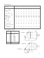
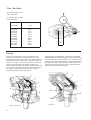
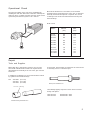
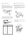
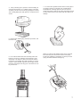
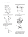
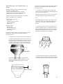
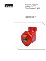
Service Manual
ASM 3.1 -F11
F11-5 through -250
Catalog 9129 8205-02
Februari 2001, GB
Safety Precautions
Certain service procedures may require the vehicle/machine to be disabled (wheels raised off
ground, work function disconnected, etc.) while performing them in order to prevent injury to
technician and bystanders.
Use caution when dealing with hydraulic fluid under pressure. Escaping hydraulic fluid under
pressure can have sufficient force to penetrate your skin causing serious injury.
Table of Contents
Specifications ....................................................... 3
Design .................................................................. 4
Operational Check ............................................... 5
Repair ................................................................... 5
- Tools ................................................................. 5
- Shaft Seal Replacement ................................... 6
- Disassembly, F11-5 through F11-150 ............. 6
- Disassembly, F11-250 ..................................... 8
- Reconditioning and Replacement of parts ........ 9
- Reassembly, F11-5 through F11-150 ............ 10
- Reassembly, F11-250 .................................... 12
- Needle Bearing installation, cylinder barrel ..... 13
Parts Identification .............................................. 14
- F11-5 through F11-150 ................................... 14
- F11-250 ........................................................... 15
2
Specifications
Designation
Displacement
(cm3/rev)
Operating
Peak
F11-5
F11-10
F11-19
F11-28
F11-39 F11-58 F11-78
F11-110 F11-150
F11-250
4.88
9.84
19.0
28.1
38.7
58.2
78.2
110
150
242
420
420
420
420
420
420
420
420
420
420
350
350
350
350
350
350
350
350
350
350
7500
5400
150
6500
5000
150
5200
4200
125
4500
3600
125
3500
3100
100
3300
2800
100
3000
2600
100
2700
2400
100
pressure
(bar)
Max continuous
(bar)
Operating speed (rpm)
Max
Max continuous
Min continuous
12000 10000
8500
6800
200
200
Power output
Max
(kW)
Continuous
(kW)
Flow
(litres/min)
at 1000 rpm (theoretical)
Torque
(Nm) at 100 bar
(theoretical)
18
28
45
58
72
95
120
150
200
300
13
20
32
40
52
68
85
110
145
190
4.88
9.84
19.0
28.1
38.7
58.2
78.2
110
150
242
7.8
15.7
30.2
44.7
61.6
92.5
124
175
239
385
Screw Tightening Torque.
Series
F11 - 5
- 10
- 19
Tightening torque
(Nm)
- 78
-110
-150
24±4
48±8
48±8
60±10
105±20
105±20
220±35
220±35
220±35
-250
See Fig.
- 28
- 39
- 58
See table
F11-5 through F11-150
220±35 Nm
325±25 Nm
F11-250
3
Gear Backlash
F11-005 through F11-110
0.05 - 0.20 mm
F11-150 through F11-250
0.10 - 0.30 mm
Frame size
mm
F11-005
F11-010
F11-019
F11-028
F11-039
F11-058
F11-078
F11-110
F11-150
F11-250
25.0
31.3
37.5
42.0
47.5
55.0
62.5
65.6
75.0
75.0
"R"
Design
Series F11 pumps/motors consist of a rotating group
contained in a split housing. Spherical pistons (1) with
laminated piston rings (2) operate at a 40° angle relative to
the shaft (3). Series F11-5 through -78 employ five pistons,
series F11-110 and -150 seven, and series F11-250 nine
pistons. As the shaft turns, the pistons are driven in a
reciprocating movement in the cylinder barrel (4). When the
unit is used as a pump, the oil passes from the inlet port to
the cylinder barrel and is then forced to the outlet port
through the pumping action of the pistons.
5
A spring device (a retaining ring, a leaf spring, or Belleville
washers) maintains the barrel against the valve plate (item 5,
F11-5 through -150) or the end cap (item 7, F11-250). A ring
gear (6) on the shaft meshes with the corresponding teeth of
the barrel (4) so that the cylinder barrel always rotates at the
same speed as the shaft (3). The shaft is supported by two
heavy duty tapered roller bearings (8).
7
4
4
2
2
6
1
1
6
3
8
Series 5 through 150
4
3
8
Series 250
Operational Check
The general condition of the unit can be established by
checking the drain flow. Remove the drain line and keep the
drain port above a suitable container. Run the unit at normal
speed and pressurize the system to 150 - 200 bar .
Measure the drain flow for one minute; if it exceeds the
maximum figures shown below, the unit is worn or damaged
internally and should be replaced or repaired. Also, check
for leakage at the shaft seal and between the bearing and
barrel housings.
Drain Flow
Series
Normal
(l/m)
Max.
(l/m)
F11-5
F11-10
F11-19
0.2
0.3
0.4
1.0
1.5
2.0
F11-28
F11-39
F11-58
0.4
0.5
0.7
2.0
2.5
2.7
F11-78
F11-110
F11-150
F11-250
1.0
1.0
1.2
1.5
3.0
3.0
3.0
3.0
Repair
Tools and Supplies
Metric Allen keys, retaining ring spanners, and a torque
wrench with suitable metric sockets are required for the
disassembly and assembly of the F11 series, plus common
hand tools.
A special tool, P/N 370 6250, is required for the removal and
re-assembly of the F11-250 barrel post.
In addition, the following tools are recommended for installing cylinder barrel needle bearings:
P/N
370 6526
370 6527
370 6528
(F11-110)
(F11-150)
(F11-250)
Barrel post installation tool
F11-110, -150 only
The following lapping compound can be used for reconditioning valve plates:
Time Saver 60
Time Saver 80
P/N 546 390 - 2400
P/N 546 390 - 3200
Needle bearing installation tool
5
Shaft Seal Replacement
Disassembly, Series F11-5 through
-150
Note
The unit does not have to be taken apart.
Remove the retaining ring and the back-up washer (units
designated F11C and F11D might not have a back-up
washer). Without damaging the shaft, punch through the
casing of the seal with a screwdriver and remove the seal.
Check the shaft sealing surface for corrosion and other
damage.
Before taking the unit apart, remove the shaft coupling (if
applicable) and thoroughly clean the outside of the unit; seal
the ports with suitable plugs or covers.
1. Remove the four metric cap screws. By utilizing two
screwdrivers, pull the housings apart as shown. Retain
the split shim located between the spacer ring and the
barrel housing.
Chamfer
The tool shown in the figure can be used to facilitate the
installation of the new seal. Be careful not to cut the seal on
the shaft key or spline. The chamfer of the back-up washer
should face the seal when installed (concerns N-seal).
2. Mark the pistons and the corresponding ball sockets
with a felt-tipped pen.
3. Remove the pistons by pulling them out when in line
with the shaft as shown.
Dia."D"
3 mm
Series
F11-
6
Dia. "D"
(mm)
5
10
35
19
52
28
62
39
58
65
78
110
72
150
250
80
4. Using a bearing press, push the shaft assembly out
of the bearing housing on a suitable support. The shaft
assembly can also be removed by grasping the housing
and carefully hitting the shaft against a wooden block as
shown.
7. To remove the cylinder barrel from the housing (does
not apply to Series F11-28 and -58), carefully hit the
housing/barrel assembly against a piece of wood as
shown; the barrel as well as the valve plate will be forced
out. Be careful to protect the barrel and valve plate from
damage.
5. Remove the retaining ring, the back-up washer, and
the shaft seal.
6. Do not disassemble the shaft assembly unless the
bearings are worn or damaged. If the bearings or the
shaft have to be replaced, remove the locknut and the
tab washer, and position the shaft assembly on a piece
of pipe or other suitable support that fits snugly around
the shaft and supports the ring gear. The shaft can now
be pressed out.
Series F11-28 and -58 cylinder barrel can be removed
from the barrel post after removal of the leaf spring
locating pin (utilizing a screwdriver as shown), the leaf
spring, and the hold-down bearing ring.
7
Disassembly, Series F11-250
Position the unit on a table provided with a hole for the shaft
or on a suitable fixture.
1. Remove the cap over the barrel post locating
screw by forcing a screwdriver through the top of the
cap and pulling it out. Remove the locating screw.
3. Remove the four cap screws and the barrel
housing. Remove the cylinder barrel off the pistons.
4. With a felt-tipped pen, mark the pistons and the
corresponding shaft sockets so that the pistons can
be re-installed in their original positions. Hold the
pistons as shown and lift them out.
2. Insert tool P/N 370 6250 (without the sleeve)
and knock the barrel post out of the end cap.
Remove the three cap screws and the end cap.
Retain the split shim located between the barrel
housing and the end cap.
Older version F11-250
8
5. Using a bearing press, push the shaft assembly
out of the bearing housing while positioning the
housing on a suitable support. The shaft assembly
can also be removed by grasping the housing and
carefully hitting the shaft against a wooden block.
Reconditioning and Replacement of
Parts
After disassembly, all parts should be thoroughly
cleaned in a suitable solvent.
Caution: Follow directions for use of solvent
carefully.Protect your hands and eyes from the
solvent.Solvent may also be inflammable.
If leakage of the F11 unit was too high, the following
parts are generally worn or damaged:
Series F11-5 through -150:
- Valve plate
- Cylinder barrel port surface
(facing valve plate)
- Piston rings
Production of the spherical piston ring is discontinued.
The old ring and piston has to be replaced by the
laminated version.
3. On series F11-5 through -150, the valve plate
surface can be reconditioned by careful lapping. Use
'Time Saver' (refer to page 5).
Series F11-250 end cap port surface can be lapped
but the bearing plate must be replaced if worn.
Note
When lapping the valve plate, up to .002 in. can be
removed. If .002 in. is not sufficient to obtain a flat
surface free of scratches, the part should be replaced.
Series F11-250:
- Bearing plate
- End cap port surface
(facing bearing plate)
- Piston rings
4. If the bearing cups are loose, the shaft lock nut
should be tightened. Correct bearing pre-load has
been obtained when the spacer ring can be moved
sideways without being loose. Note, for the bigger
units quite a substantial force is required.
Scratches and wear marks on these parts always affect the
performance of the unit; they should be replaced if
scratched or worn.
1. Shaft seal and o-rings should always be replaced.
2. Replace spherical piston rings that are worn more
than 50 % of the spherical surface as shown. A small
retaining ring pliers will facilitate the removal. When
installing a new piston ring, make sure the spherical
surface coincides with the shape of the piston head.
Max 50%
If play indicated in the figure is exceeded then
replace all piston and ring assemblies in the unit.
Never replace individual worn piston and ring
assemblies.
5. Check that the shaft surface in contact with the
shaft seal is in good condition; if grooved, corroded,
or otherwise damaged, the shaft should be replaced.
Max .0.2 mm
9
Reassembly, Series F11-5 through
-150
All parts should be thoroughly cleaned and lightly lubricated
with hydraulic fluid. Reassembly is carried out in reverse
order of disassembly.
Caution: Follow directions for use of hydraulic fluid carefully. Protect your hands and eyes from fluid. Fluid may also
be flameable.
The following valve plates are available (designation
appears on the nameplate):
M = Bi-directional, motor or pump operation
L = L.H. rotation, pump operation
R = R.H. rotation, pump operation
G = L.H. rotation, internal drain, motor operation
J = R.H. rotation, internal drain, motor operation
H = Bi-directional, motor operation, high pressure
Q = Bi-directional, motor operation, low noise
3. The cylinder barrel retaining ring (does not apply
to Series F11-28 and -58) should be installed as
illustrated below. When installing the barrel in the
housing, the opening of the retaining ring should face
the housing cut-out as shown; the barrel has to be
pushed down to overcome the spring force of the
retaining ring.
1. Place the cylinder barrel housing in a vice as
shown.
Some resistance should be felt when trying to turn
the cylinder barrel by hand; if no resistance is felt, the
retaining ring must be replaced.
2. Install the valve plate making sure it is seated
properly in the housing; when installed correctly, the
visible face of the valve plate should appear as
shown.
M
Q
L
G
Drain port
Note
R
H
The internal drain valve plate G is shown from the back side
of the plate. From the front, when installed, it looks the same
as the M plate.
10
Regarding installation of needle bearings in
F11-110 and -150 cylinder barrels, refer to
page 16.
4. Series F11-28 and -58 utilize a leaf spring for
barrel hold-down. Install the cylinder barrel on the
barrel post, install the hold-down ring and the leaf
spring, and secure the spring with the locating pin.
5. Install the guide spacer (with new o-rings) to the
barrel housing; make sure one of the cut-outs is in
the position shown, and leave room for the split shim
between the spacer and the housing .
8. Locate the marked tooth of the shaft ring gear.
Cut out
Note
If the shaft assembly has been taken apart, refer to
"Reassembly, Series F11-250" for instructions.
6. Install the split shim as illustrated. Make sure the
shim is properly located in the barrel housing recess.
Correct thickness of the shim should result in a gear
backlash of .05 to .15 mm. If any part of the rotating
group has been replaced, it might be necessary to
change to a shim of different thickness; backlash is
checked according to paragraph 12 (page 12).
9. Position the shaft/piston assembly over the
housing/barrel assembly as shown, so that the timing
marks of the ring gear and cylinder barrel are lined
up. Locate each piston into the corresponding,
previously marked cylinder bore.
10. If the timing marks don't match as illustrated,
carefully pull the shaft assembly out of mesh with the
ring gear and reposition correctly.
7. Two teeth on the cylinder barrel and one tooth on
the ring gear are marked to ensure that the pistons
are in line with the cylinder bores. Position the
cylinder barrel so that the markings are visible in the
spacer cut-out as shown, this assures correct timing
of the shaft and the cylinder barrel.
11. Install the bearing housing with a new shaft seal
on the shaft/bearing assembly, being careful not to
cut or otherwise damage the seal. Cross-torque the
cap screws according to specifications on page 3.
11
12. Turn the shaft by hand to assure correct assembly. A
"clicking" noise generated when the shaft is rapidly turned
back and forth reveals that there is backlash between the
ring gear and the cylinder barrel. A "no noise" condition
indicates no backlash, and a thicker shim has to be installed.
The correct backlash should be .05 to .15 mm.
Reassembly, Series F11-250
1. If the shaft/bearing assembly has been taken apart,
start the reassembly by installing the ring gear over the
locating dowel pin. Press the cone of the large roller
bearing against the ring gear. Install the large bearing cup,
the spacer ring (note the position of the cut-outs), and the
small bearing cup. Press the small bearing cone onto the
shaft, but only so far that the spacer ring can still be moved
sideways easily.
2. Install a new tab washer and tighten the lock nut
gradually until the spacer ring between the bearing cups is
held firmly but not tight; you should be able to push the
spacer sideways with your thumbs as shown. Secure the
nut with one of the tabs of the washer.
5. Install the barrel housing and check through the drain
port that the timing is correct. Cross-torque the cap screws
according to specifications (page 3).
6. Install new o-rings on the end cap; one o-ring is located
in the barrel post bore. Screw tool P/N 370 6250 (without
nut and bearing) into the barrel post, and install the end cap
over the tool spindle against the block housing. Install the
split shim as shown, making sure it is located correctly in the
barrel housing recess.
Note
If the lock nut has been tightened too much as to allow the
spacer to be moved sideways, the bearings have to be
removed from the shaft and the assembly procedure started
over again.
3. Install a new shaft seal and push the shaft assembly into
the bearing housing. Install the pistons in the ball sockets.
4. If a new cylinder barrel is used, install the groove pins
that locate the bearing plate, the internal retaining ring, and
the needle bearings (refer to page 14). Install the barrel
post/bearing assembly in the cylinder barrel. Locate each
piston into the corresponding, previously marked cylinder
bore, and position the cylinder barrel assembly on the ring
gear as shown so that the timing marks are lined up.
12
7. Install the nut/bearing of the tool on the spindle, and , by
tightening on the nut,pull the barrel post partly into the end
cap. Install the three cap screws and tighten according to
specification (page 3).
Drift pin
Sleeve
8. By further tightening on the nut, pull the block post
completely into the end cap; do not overtighten.
9. Remove the assembly tool. Install the cap screw that
secures the barrel post, and torque it to .40-.45 Nm; back
off 1/3 turn to obtain correct axial play. Push the seal cap
over the screw head.
10. Check the backlash through the drain port; correct
backlash is .10-.30 mm.
Needle Bearing Installation
1. Install the sleeve and a needle bearing on the drift pin;
press the bearing to the bottom of the cylinder barrel
(dimension A).
F11-110, -150
2. Remove the sleeve, install the second needle bearing on
the drift pin and press in place (dimension B).
F11-250:
A
B
Retaining
Ring
Series
Dim. A
mm
Dim. B
mm
F11-110
56.0
4.5
F11-150
61.5
10.0
Refer to page 5 for information on recommended tools.
Note
1. Install a needle bearing on the drift pin (there is no
sleeve); press in place so that it just touches the
retaining ring.
When installing the needle bearings, the marked end of the
cage should face the drift pin or sleeve.
2. The second needle bearing should be located
against the one previously installed.
13
Item
Title
110
121
131
132
211
221
222
233
236
237
311
321
411
415
431
436
438
439
440
442
451
452
460
464
470
474
475
486
488
491
Barrel Housing Assy
Valve Plate
Hex Socket Plug
Seal Washer
Bearing Housing
O-Ring
O-Ring
Shaft Seal
Back-up Ring
Retaining Ring
Shaft
Flat Key
Cylinder Barrel
Needle bearing
Barrel Retaining Ring
Bearing Ring
Leaf Spring
Pivot Pin
Piston Assy
Piston Ring
Pin
Ring Gear
Taper Roller Bearing
Spacer Ring
Taper Roller Bearing
Lock Washer
Round Nut
Guide Spacer
Shim
Hex Socket Screw
492
110
491
131,132
121
431
411
436
438
439
221
442
440
222
488
486
451
311
321
452
460
464
470
474
475
211
233
236
237
14
Item
Title
111
131
132
211
222
223
224
233
236
237
311
321
411
413
414
415
422
423
424
425
426
427
428
429
433
440
442
451
452
461
462
464
470
474
475
481
488
491
493
End Cap
Hex Socket Plug
Seal Washer
Bearing Housing
O-Ring
O-Ring
O-Ring
Shaft Seal
Back-up Ring
Retaining Ring
Shaft
Flat Key
Cylinder Barrel
Spring Pin
Retaining Ring
Needle Bearing
Spacer Sleeve
Barrel Spindle
Sliding Plate
Taper Roller Bearing
Spacer Washer
Retaining Ring
Hex Socket Screw
Cap Plug
Disc Spring
Piston Assy
Piston Ring
Pin
Ring Gear
Taper Roller Bearing Cone
Taper Roller Bearing Cup
Spacer Ring
Taper Roller Bearing
Lock Washer
Round Nut
Barrel Housing
311
Shim
Hex Socket Screw
Hex Socket Screw
452
461
462
464
470
471
475
429
428
493
111
223
488
491
481
132
131
413
421
411
442
440
451
321
224
423
414
415
422
425
433
426
427
211
233
236
237
15
Please contact our sales representative:
Parker Hannifin AB
VOAC Hydraulics Division
SE-461 82 Trollhättan
Sweden
Tel +46 520 986 00
Fax +46 520 371 05
www.parker.com
Catalog 9129 8205-02
Februari 2001, GB