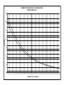
1
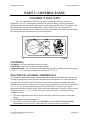
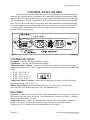
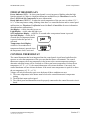
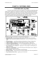
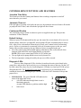
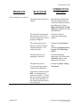
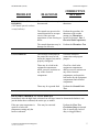
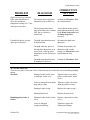
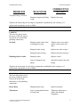
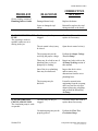
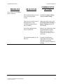
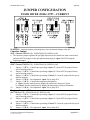
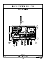
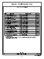
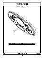
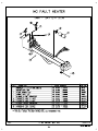
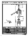
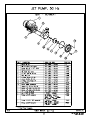
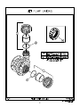
Service Manual
International Edition
July 2007
T:\TECH\Service Instructions\TRE_Cover.doc
Component Explanation
& Diagnosis
T:\TECH\Service Instructions\TRE_Component.doc
TIGER RIVER COMPONENT EXPLANATION
AND DIAGNOSIS
TABLE OF CONTENTS
SECTION I: EXPLANATION
PART 1: Control Panel
Section I: 1
CONTROL PANEL (1997)……………………………………………. Section I: 1
1997 Control Panel Illustration…………………………………….. Section I: 1
CONTROLS………………………………………………………... Section I: 1
Electronic Control Thermostat……………………………………... Section I: 1
CONTROL PANEL (IQ 2000)………………………………………… Section I: 2
IQ 2000 Control Panel Illustration…………………………………. Section I: 2
CONTROL BUTTONS……………………………………………. Section I: 2
FEATURES…………………………………………………………Section I: 2
INDICATORS/DISPLAYS………………………………………... Section I: 3
Control Thermostat………………………………………………… Section I: 3
PART 2: Control Box
Section I: 5
CONTROL BOX (IQ 2000)……………………………………………. Section I: 5
Control Box Illustration……………………………………………. Section I: 5
CONTROL BOX FUNCTIONS AND FEATURES………………. Section I: 6
Actuation Time Delay……………………………………………… Section I: 6
Automatic Time-out………………………………………………... Section I: 6
Continuous Filtration………………………………………………. Section I: 6
Default Settings…………………………………………………….. Section I: 6
Diagnostic LEDs…………………………………………………… Section I: 6
Thermistor Verification…………………………………………….. Section I: 7
High Limit Thermostat……………………………………………... Section I: 7
PART 3: Electrical Sub-Components
Section I: 9
Bonding Terminal……………………………………………………… Section I: 9
Circuit Breaker…………………………………………………………. Section I: 9
GFCI……………………………………………………………………. Section I: 9
Grounding Lug…………………………………………………………. Section I: 10
Terminal Block………………………………………………………….Section I: 10
Thermistors…………………………………………………………….. Section I: 10
PART 4: Major Electrical Components
Section I: 11
Circulation Pump………………………………………………………. Section I: 11
Heater…………………………………………………………………... Section I: 11
Jet Pump………………………………………………………………... Section I: 11
Spa Light……………………………………………………………….. Section I: 12
PART 5: Jets and Plumbing
Section I: 13
Air Control Valve………………………………………………………. Section I: 13
Check Valves…………………………………………………………... Section I: 13
Diverter Valve………………………………………………………….. Section I: 13
Drain/Heater Return System…………………………………………… Section I: 13
Filter……………………………………………………………………. Section I: 14
i
t:\tech\manual\tgrriver\export\toci50hz_tra.doc
TABLE OF CONTENTS
Jets………………………………………………………………….. Section I: 14
Safety/Secondary Suction System………………………………….. Section I: 14
SECTION II: DIAGNOSIS
Entire Spa Inoperative………………………………………………….. Section II: 1
Spa Light Inoperative…………………………………………………... Section II: 2
Jet Pump Inoperative…………………………………………………… Section II: 2
Circulation Pump Inoperative………………………………………….. Section II: 3
Heater Inoperative……………………………………………………… Section II: 3
Ready Indicator Blinking………………………………………………. Section II: 5
GFCI Tripping………………………………………………………….. Section II: 5
High Limit/Thermal Cut-Off Tripping…………………………………. Section II: 5
Jet Pump Leaking………………………………………………………. Section II: 6
Circulation Pump Leaking……………………………………………... Section II: 7
Heater Leaking…………………………………………………………. Section II: 7
Flow Restricted, Jet Pump………………………………………………Section II: 8
Flow Restricted, Circulation Pump…………………………………….. Section II: 8
SECTION III: TESTS
Source Voltage Test……………………………………………………. Section III: 1
GFCI Test………………………………………………………………. Section III: 1
Ground Fault Test……………………………………………………… Section III: 1
Output Voltage Test, Spa Light………………………………………... Section III: 4
Output Voltage Test, Ozonator………………………………………… Section III: 4
Output Voltage Test, Circulation Pump……………………………….. Section III: 4
Output Voltage Test, Jet Pump………………………………………… Section III: 5
Output Voltage Test, Heater…………………………………………… Section III: 5
Control Panel Test (1997 Model Spas ONLY)………………………… Section III: 5
Thermostat Test, Control (1997 Model Spas ONLY)………………….. Section III: 6
Control Panel Test (IQ 2000 control panels)…………………………... Section III: 7
Thermistor Test………………………………………………………… Section III: 8
Flow Test, Jet Pump…………………………………………………… Section III: 9
Flow Test, Circulation Pump…………………………………………... Section III: 9
Appendix: Jumper Configuration………………………………………………….Appendix: 1
Thermistor Temperature versus Resistance Graph………………….… Appendix: 2
INDEX
ii
t:\tech\manual\tgrriver\export\toci50hz_tra.doc
50 HZ
SECTION I:
EXPLANATION
t:\tech\extranet\tiger river service - export\tiger river service manual 50hz support\cvrpages50hz_tra.doc
TIGER RIVER (50 Hz)
Section I: Explanation
PART 1: CONTROL PANEL
CONTROL PANEL (1997)
The 1997 control panel allows the spa user to regulate the light, jets, and water
temperature. The 1997 control panel consists of the panel assembly, electronic thermostat,
control circuit board, jets button, light button, control thermostat dial, and a 7-pin ribbon cable
that connects the electronic thermostat to the control circuit board. The control panel is
connected to the control box via a ribbon cable. If the ribbon cable is disconnected or damaged,
the control panel and spa functions will not work properly.
CONTROLS
Jets Button – activates and deactivates the jet pump.
Light Button – activates and deactivates the spa light.
Temperature Dial – raises and lower the thermostat setting (the maximum temperature setting
is 107.5° F / 42° C; the lowest temperature setting is 50° F / 10° C).
ELECTRONIC CONTROL THERMOSTAT
The electronic control thermostat is located behind the temperature dial and allows the spa user
to select the temperature of the spa water that the heater will maintain. The control thermostat
compares the water temperature in the heater to the current temperature setting to determine
when the heater will be switched on. If the actual water temperature is below the set temperature
(±2° F / 618 C), the control thermostat will activate the heater. Conversely, the control
thermostat will not activate the heater if the actual water temperature is equal to or above the set
temperature (±2° F / 618 C). Voltage will only be allowed to pass on to the heater if three
conditions are met:
1. The water temperature in the heater must be below the control thermostat’s temperature
setting.
2. The high limit must not be tripped.
3. The control panel and thermistors (see Thermistors located in Part 3: Electrical SubComponents) must be properly connected to the control box main circuit board.
Component Explanation and Diagnosis
CED-001A EXPLANATION.DOC
Section I: 1
TIGER RIVER (50 Hz)
CONTROL PANEL (IQ 2000)
The IQ 2000 control panel allows the spa user to regulate and view the status of the spa
functions. Spa functions that are regulated by the control panel include the temperature control,
light, jets, spa lock, and temperature lock. The control panel also displays the status of the light,
jets, set temperature, spa lock, temperature lock, power indicator, ready indicator, and spa high
limit. The IQ 2000 control panel face consists of three interconnected items: the digital display,
the control buttons, and two indicator lights. The control panel is connected to the control box
via a ribbon cable. If the ribbon cable is disconnected or damaged, the control panel and spa
functions will not work properly.
CONTROL BUTTONS
Jets Button – activates and deactivates the jet pump.
Light Button – activates and deactivates the spa light.
Temperature Plus (+) Button – raises the set temperature on degree at a time (the maximum
temperature setting is 104° F / 40° C; higher temperatures may be reached but are indicated with
a code:
• UT 1 = 105° F/ 40.5° C
• UT 2 = 106° F / 41° C
• UT 3 = 106.5° F / 41.5° C
• UT 4 = 107.5° F / 42° C).
Temperature Minus (–) Button – lowers the set temperature on degree at a time (the lowest
temperature setting is 80° F / 26.5° C).
Hidden, Tiger Button (located underneath the Tiger River Spas logo) – activates and
deactivates the spa lock and temperature lock. (see Features below).
FEATURES
Spa Lock – disables the control panel – none of the spa functions can be accessed. To activate or
deactivate the spa lock, press the Hidden, Tiger button and the Temperature Minus (–) button at
the same time and hold for 5 seconds.
Temperature Lock – disables the set temperature function – the set temperature cannot be
changed. To activate or deactivate the spa lock, press the Hidden, Tiger button and the
Temperature Plus (+) button at the same time and hold for 5 seconds.
Section I: 2
Component Explanation and Diagnosis
CED-001A EXPLANATION.DOC
TIGER RIVER (50 Hz)
Section I: Explanation
INDICATORS/DISPLAYS
Power Indicator (RED) – lit when control panel is receiving power; blinking when the high
limit has tripped or if there is a high limit thermistor malfunction (see Thermistors located in
Part 3: Electrical Sub Components for more information).
Ready Indicator (GREEN) – lit when the actual temperature of the spa water is within ±2° F /
1±° C of the temperature setting; blinking when there is a control thermistor and/or control panel
malfunction (see Thermistor Verification located in Part 2: Control Box for more information
about thermistor malfunctions).
Jets Display – visible when the jets are on.
Light Display – visible when the light is on.
Set Temperature Display – visible for 30 seconds after a temperature button is pressed.
Spa Lock Display – visible for 30
seconds after a temperature button
is pressed when the spa lock is
activated.
Temperature Lock Display –
visible for 30 seconds after a
temperature button is pressed when
the temperature lock is activated.
CONTROL THERMOSTAT
The control thermostat has been integrated into the control panel circuit board, and allows the
spa user to select the temperature of the spa water that the heater will maintain. The control
thermostat compares the water temperature in the heater to the current temperature setting to
determine when the heater will be switched on. If the actual water temperature is below the set
temperature (±2° F / 618 C), the control thermostat will activate the heater. Conversely, the
control thermostat will not activate the heater if the actual water temperature is equal to or above
the set temperature (±2° F / 618 C).
Voltage will only be allowed to pass on to the heater if three conditions are met:
1. The water temperature in the heater must be below the control thermostat’s temperature
setting.
2. The high limit must not be tripped.
3. The control panel and thermistors must be properly connected to the control box main circuit
board.
Component Explanation and Diagnosis
CED-001A EXPLANATION.DOC
Section I: 3
TIGER RIVER (50 Hz)
Section I: 4
Component Explanation and Diagnosis
CED-001A EXPLANATION.DOC
TIGER RIVER (50 Hz)
Section I: Explanation
PART 2: CONTROL BOX
CONTROL BOX (IQ 2000)
The “brain” of the control system is the control box. The control box contains the primary
control circuitry, which receives and processes signals from the control panel and regulates the
spa functions. In addition, the control box receives source voltage from the main power line and
routes the appropriate load or output voltage to each electrical component (jet pump, circulation
pump, ozonator, spa light, heater, and control panel). The control box assembly contains no
serviceable components, so the entire box must be replaced if a failure occurs.
The following items are pictured above, in the control box illustration.
• Diagnostic LEDs – convey the status of three circuits: high limit, heater, and control.
• Ribbon Cable Connection Terminal (Control Panel) – seats the control panel’s ribbon
cable.
• Program Jumpers – control the spa functions and settings (see Jumper Configuration).
• Capacitor Jumper – regulates the spa light capacitor (see Jumper Configuration).
• Connector (Control Thermistor) – receives the control thermistor connection wire.
• Connector (High Limit Thermistor) – receives the high limit thermistor connection wire.
• Flag Terminals, Power Connection – supply power to the spa light, circulation pump, jet
pump, and ozonator.
• Main Power Terminal Block – receives the main power line and passes source voltage on
to the circuit board and heater relays.
• Heater Ground – attaches to the ground wire from the heater.
• Bonding Terminal – connects all of the solid copper bonding wires to the main ground line.
• Flag Terminals, Heater Power– supplies power to the heater.
Component Explanation and Diagnosis
CED-001A EXPLANATION.DOC
Section I: 5
TIGER RIVER (50 Hz)
CONTROL BOX FUNCTIONS AND FEATURES
Actuation Time Delay
This feature prevents the control panel buttons from switching components on and off
more than once per second.
Automatic Time-out
If the spa light or jet pump is left on by the spa user, the automatic time-out feature will turn the
jet pump off after 2 hours, and will turn the spa light off after 6 hours.
Continuous filtration
The circulation pump is turned on whenever power is supplied to the spa. This provides
continuous 24-hour filtration.
Default Settings
Whenever power is disconnected from the spa, the control box circuit board will revert to its
default settings, which are: spa light OFF and jet pump OFF (the circulation pump is always
ON). After power is disconnected from the spa, always wait 1 minute before reconnecting
power. If power is prematurely reconnected to the spa, disconnect power to the spa, wait 1
minute, then reconnect power to the spa. Whenever power is supplied to the spa:
• All of the control panel LEDs should light up momentarily, this verifies that all of the
indicator lights and LEDs in the digital display are operative.
NOTE: There are no control panel LEDs on 1997 model spas.
• The spa light and jet pump should not activate by themselves.
• The last temperature setting selected by the spa user will be restored.
Diagnostic LEDs
There are three diagnostic LEDs, which are located on the main circuit board in the
control box, and provide a quick and easy way to determine the status of the spa. (On the 1997
IQ 2000 control box, there may be a fourth diagnostic LED that is red and says FLOW, please
disregard this LED. The FLOW LED is not used. It will always be on, and should not be
considered when troubleshooting the spa. The flow LED does NOT determine if the spa has
proper flow).
1. LIM OK LED – The green LIM OK LED indicates the
status of the high limit circuit.
•
A lit LED indicates the high limit circuit is
functioning properly.
An unlit LED indicates a problem with the high
•
limit circuit.
Section I: 6
1
LIM OK
2
HTR ON
3
CONTROL
UNPLUGGED
Component Explanation and Diagnosis
CED-001A EXPLANATION.DOC
TIGER RIVER (50 Hz)
Section I: Explanation
2. HTR ON LED – The red HTR ON indicates the status of the heater circuit.
•
A lit LED indicates the control circuit is supplying DC voltage to the coil of the
heater relay. If the heater relay is not defective and the interlock relay is closed, AC
voltage will be supplied to the heater, and the heater will be on. If the interlock relay
is open, or if the relay or wiring is bad, the HTR ON LED will be on, but no AC
voltage will be supplied to the heater, the heater will be off.
•
An unlit LED indicates that no DC voltage is being supplied to the heater relay.
3. CONTROL UNPLUGGED LED – The red CONTROL UNPLUGGED LED indicates
whether the Control Panel Assembly is plugged into the Control Box Assembly.
•
A lit LED indicates the control panel is not communicating with the control box –
usually caused by disconnected or damaged ribbon cable.
•
An unlit LED indicates the control panel is properly connected to the control box.
Thermistor Verification
The control circuitry verifies the condition of the thermistors. Power to the spa light, jet pump,
and heater will be disconnected if the control circuitry detects a high limit thermistor
discrepancy. Power to the heater will be disconnected if the control circuitry detects a control
thermistor discrepancy. There are three common discrepancies that will cause the control
circuitry to disconnect power to the heater and/or the spa light and jet pump:
1. If a thermistor circuit is open (thermistor unplugged).
2. If a thermistor circuit is shorted (damaged thermistor wires – bare wires are touching each
other).
3. If the spa water temperature is near or below freezing (32° F / 0° C) – this appears to be an
open circuit to the control circuitry. (See Thermistors located in Part 3: Electrical SubComponents).
In addition, power will be disconnected from the spa light, jet pump, and heater if the spa water
temperature exceeds the high limit value (118° F / 48° C). To reset a spa after the control
circuitry has disconnected power to the heater and/or spa light and jet pump, you must
disconnect power to the entire spa for a minimum of 1 minute, correct the failure or discrepancy,
and then reconnect power to the spa.
HIGH LIMIT THERMOSTAT
The high limit thermostat is part of the control box circuitry, and is designed to prevent the spa
water from overheating. The high limit thermostat compares the water temperature in the heater
to the high limit value (118° F ±2° F / 488 C), which cannot be set or adjusted by the spa user. If
the high limit value is exceeded, the high limit will trip. When the high limit trips the spa light,
jet pump, and heater cannot be switched on until the spa water temperature cool down below the
high limit value, and the high limit thermostat is reset by disconnecting power to the spa for 1
minute then reconnecting power to the spa.
NOTE: The control thermostat circuitry is located in the control panel (for information about the
control thermostat see Part 1: Control Panel).
Component Explanation and Diagnosis
CED-001A EXPLANATION.DOC
Section I: 7
TIGER RIVER (50 Hz)
Section I: 8
Component Explanation and Diagnosis
CED-001A EXPLANATION.DOC
TIGER RIVER (50 Hz)
Section I: Explanation
PART 3: ELECTRICAL SUB-COMPONENTS
Bonding Terminal
The bonding terminal is located on the exterior of the control box, and is connected to
two sources of ground: the ground wire on the main power line, and a solid copper ground wire.
Safety standard dictates that the heater, along with any components not permanently connected
or “hard wired” to the control box must be attached to the bonding terminal with a minimum 8.4
mm2 solid copper wire. Components that are plugged into a control box receptacle are not
considered “hard wired” (permanently connected), and therefore must be attached to the bonding
terminal. Also, all metal structures permanently placed within five feet of the spa (metal ladders,
metal water pipes, metal enclosures of electrical equipment, metal equipment, etc.) must be
attached to the bonding terminal as well. If the spa is located on a reinforced concrete pad, the
reinforcement steel should also be bonded to the bonding terminal (please refer to the Owner’s
Manual for more details).
Circuit Breaker
A circuit breaker, located in a sub-panel, is a switch that will not tolerate electrical
current greater than its rating. Like the GFCI (see below), the breaker interrupts the flow of
electrical current when tripped. However, the difference in the operating principle between the
breaker and GFCI is that the GFCI is primarily designed to protect the spa user from current
leakage, and the circuit breaker is implemented to protect the electrical equipment from
overloads. GFCI devices do nothing in over-current (current draw that exceeds the tolerance of
the circuit) situations that do not result in any current leaking to ground. On the other hand, there
may be a flow of current in the system, which does not exceed the circuit breaker rating (so it
will not trip), but the GFCI will react if there is sufficient current leakage to ground.
GFCI
A GFCI (Ground Fault Circuit Interrupter) is a protective device that is sensitive to small
amounts of electric current flowing to ground. A ground fault greater than 5 mA (milliamps),
61 mA, will cause the GFCI to trip, which disconnects power to the spa until the ground fault is
corrected and the GFCI is reset. The GFCI is designed to protect the spa user from electrical
shocks (as well as the spa’s circuitry from overloads and shorts). Without a GFCI device
installed on a spa, a significant ground fault could be fatal and would likely burn the weakest
(smallest) link in the circuitry (i.e. a wire, circuit board trace, or terminal block connection).
However, the GFCI will not protect anyone who comes in contact with the hot and neutral wires,
and the GFCI offers no protection from voltage introduced from an exterior source (radio, hair
dryer, etc.). When the GFCI trips, it normally indicates current leakage to ground caused by
faulty insulation, wet wiring, or wet equipment connected to the circuit.
GFCI devices always have a test button and may be reset after they have tripped. The test
button trips the GFCI when pressed, which disconnects power to the spa. When the GFCI is
reset, the circuit will be completed unless a ground fault of 5 mA or more is detected then the
GFCI will trip as soon as the GFCI is reset.
NOTE: Spa owners should test the GFCI before each use of the spa by performing the GFCI
Test described in the testing section of this manual).
Component Explanation and Diagnosis
CED-001A EXPLANATION.DOC
Section I: 9
TIGER RIVER (50 Hz)
Grounding Lug
The grounding lug is a terminal located on the exterior of spa components (i.e. the heater,
jet pump, ozonator, etc.) that is intended to receive a ground wire that is connected to the
bonding terminal. However, only heaters and any components not permanently connected to the
main circuit board (see Bonding Terminal) are required to be attached to the bonding terminal.
Terminal Block
The terminal block receives the source voltage from the main power line, and delivers
voltage to the control circuitry in the control box. Improperly wiring or jumping the terminal
block may permanently damage the control box components.
Thermistors
A thermistor is an electronic temperature-sensing device that consists of three main parts:
electrical wires, a connector, and a temperature-sensing probe. The thermistor’s resistance or
ohmic value corresponds with its temperature. When the thermistor’s temperature changes the
ohmic value also changes. The thermistor’s connector plugs directly into a circuit board that is
able to determine the water temperature based on the thermistor’s resistance. The control
circuitry uses the control thermistor to determine the actual temperature of the spa water, and
compares this value to the temperature setting of the control thermostat to regulate the heater.
The control circuitry uses the high limit thermistor to determine whether the high limit value has
been exceeded. If the high limit value is exceeded, the high limit will trip.
Thermistor Cold Weather Startup – If the spa water temperature is near freezing or below, the
high limit may trip. To reset the high limit there are two things that you can do:
1. Disconnect power to the spa. Raise the temperature of the thermistors by warming them with
a hair dryer while they are still connected to the heater. Then reconnect power to the spa.
2. Disconnect power to the spa, disconnect the thermistors from the control box, and then
connect a thermistor test tool to the control box. Reconnect power to the spa, set the
thermistor test tool so that the heater switches on, and wait a couple of minutes for the heater
to warm the thermistors. When the water temperature is well above freezing, disconnect
power to the spa, reconnect the thermistors to the control box, and then reconnect power to
the spa.
NOTE: Every time power is disconnected from the spa, power should not be reconnected for, at
least, 1 minute. If power is prematurely reconnected to the spa, disconnect power, wait 1 minute,
and then reconnect power.
Section I: 10
Component Explanation and Diagnosis
CED-001A EXPLANATION.DOC
TIGER RIVER (50 Hz)
Section I: Explanation
PART 4: MAJOR ELECTRICAL
COMPONENTS
Circulation Pump
The circulation pump consists of two main parts: an electric motor and a wet end. The
electric motor spins the impeller. The wet end contains the impeller, which is the mechanism that
moves the spa water through the jet pump. Water is supplied to the circulation pump via the
suction lines that are connected to the filter compartment and secondary/safety suction fitting.
Water is discharged from the circulation pump via the pressure lines that are connected to the
drain/heater return assembly.
Heater
For the purposes of discussion, the heater may be split into five basic sections: the heater
body, the heating element, the heat-exchange chamber, the heater inlet, and the heater outlet. The
heating element is the device that produces heat. The heater inlet supplies water to the heatexchange chamber, which is where the heat (generated by the heater element) is transferred to
the spa water. The heater outlet is where the heated spa water re-enters the plumbing lines. The
heated water reenters the bathing area of the spa through the drain/heater return. All spa control
systems implement some form of a safeguard that disconnects power to the heater when
situations arise that could cause the heating element to overheat, such as restricted water flow to
or through the heater.
No Fault 1500 Heater – The No Fault 1500 Heater body houses the control and high limit
thermistors, but what makes the No Fault 1500 heater unique are two distinguishing features.
First, the spa water never comes in direct contact with the heating element because stainless steel
heat-exchange chambers protect the heating element from direct exposure to the spa water.
Second, when the heater exceeds tolerable temperatures, power to the heater is disconnected by
the thermal cut-off, which may be reset when the heater cools down.
Jet Pump
The jet pump consists of two main parts: an electric motor and a wet end. The electric
motor turns a drive shaft, which spins an impeller. The wet end assembly (volute and volute
cover) contains the impeller, which is the mechanism that moves the spa water through the jet
pump. Water is supplied to the jet pump via the suction lines that are connected to the filter
compartment and secondary/safety suction fitting. Water is discharged from the jet pump via the
pressure lines that are connected to the jet nozzles.
Shroud, Jet Pump Motor – The jet pump motor shroud is attached to the rear of the jet pump
and promotes air circulation around the motor. The shroud vents warm air away from the jet
pump motor and out of the equipment compartment to safeguard the unit and other components
from the heat that’s generated by the jet pump motor.
Component Explanation and Diagnosis
CED-001A EXPLANATION.DOC
Section I: 11
TIGER RIVER (50 Hz)
Spa Light
Spas are equipped with a light to enhance nighttime use. The spa light illuminates the
entire bathing area and is located in the equipment compartment behind the light lens, which is
sealed to the spa shell. The spa light may be activated and deactivated from the control panel.
The light assembly or harness consists of the light socket, ballast/transformer, heat shield, and
wires that connect to the control box.
Section I: 12
Component Explanation and Diagnosis
CED-001A EXPLANATION.DOC
TIGER RIVER (50 Hz)
Section I: Explanation
PART 5: JETS AND PLUMBING
Air Control Valve
The air valve, located on the bar-top or at the jet, controls the amount of air that is
allowed to mix with water at the jets. This allows the spa user to control the water pressure at the
jets. When the air valve is closed no air is mixed with water and the water pressure at the jets is
minimal. Opening the air valve increases the amount of air that is mixed with water, and
increases the water pressure.
Check Valves
Check valves are used to regulate the direction of flow through the air, pressure, and
suction lines. Flow is permitted to travel through a check valve in only one direction. Air Check
valves are placed at the intake end of the jet and ozone air lines to prevent back flow from
entering the equipment compartment. Water check valves are placed throughout the pressure and
suction lines, and are primarily used in conjunction with the diverter valve to route water flow to
various groups of jets.
Tiger River spas have addition water check valves placed at the circulation pump and jet
pump outlets to prevent the pumps from drawing water through each other and the heater return
assembly and jet nozzles. The additional water check valves are required because the jet pump
and circulation pump use the same filter and share parts of the suction lines.
Diverter Valve
The diverter valve controls which jets are activated when the jet pump is turned on.
Groups of jets activated by the diverter valve are called jet systems. The number of jet systems
that can be activated by the diverter valve is determined by the type of spa and hence the type of
diverter valve implemented in the spa. Fundamentally there are only two types of diverter valves:
2-position and 4-position. Both types of diverter valves consist of three primary components: the
diverter body, the diverter core, and the diverter lever. The diverter body is permanently attached
to the plumbing lines and houses the diverter core; the diverter core regulates the water flow
through the diverter body; and the diverter lever is used to rotate the diverter core, which
changes the water flow through the diverter body and activates specific jet systems (refer to the
Owner’s Manual for specific information about jet systems).
Drain/Heater Return System
•
•
•
Floor Drain/Heater Return – The floor drain/heater return is located on the floor or wall of
the foot well and permits the spa water to be completely emptied with little or no bailing. The
floor drain/heater return also serves as the outlet where the heated water produced by the
heater reenters the bathing area of the spa.
Drain/Heater Return Fitting – The drain/heater return fitting prevents debris from entering
the spa’s draining system.
Drain Valves – The drain valves are located beneath the equipment compartment, and are
connected to the bleed lines and floor drain/heater return. The drain valves allows the spa to
be emptied with little or no bailing.
Component Explanation and Diagnosis
CED-001A EXPLANATION.DOC
Section I: 13
TIGER RIVER (50 Hz)
Filter
The filter prevents debris from entering the plumbing lines, cleans the spa water, and is
the primary inlet for water entering the plumbing system.
NOTE: Clogged or dirty filters are the primary cause of low flow conditions.
Jets
There are four basic parts to a jet: the face, the nozzle, the front wall fitting, and the rear
wall fitting or body. The face provides an aesthetic finish to the exterior of the jet, but provides
some functionality by retaining the nozzle in certain jets. The nozzle is the outlet, which
constrains and directs the water propelled by the jet pump. The front wall fitting seals the
opening where the jet connects to the spa shell, and retains the nozzle in certain jets. Finally, the
rear wall fitting or body houses the front wall fitting, and is where the air is mixed into the water
before it enters the tub. The amount of air mixed into the water determines the amount of
pressure produced at the jet.
Safety/Secondary Suction System
•
•
•
Safety/Secondary Suction Fitting – The safety/secondary suction fitting, located on the wall
of the foot well (usually in front of the filter compartment), prevents foreign objects from
entering the plumbing line through the safety suction valve.
Safety/Secondary Suction Filter Screen – The safety/secondary suction filter screen
prevents minute debris from entering the plumbing line through the suction fitting.
Safety/Secondary Suction Valve – The safety/secondary suction valve is a safety device
that provides an alternate route for water to be drawn into the plumbing lines should the
primary route through the filter compartment become obstructed.
Section I: 14
Component Explanation and Diagnosis
CED-001A EXPLANATION.DOC
50 HZ
SECTION II:
DIAGNOSIS
TIGER RIVER COMPONENT EXPLANATION
AND DIAGNOSIS
TABLE OF CONTENTS
SECTION II: DIAGNOSIS
Entire Spa Inoperative
Spa Light Inoperative
Jet Pump Inoperative
Circulation Pump Inoperative
Heater Inoperative
Ready Indicator Blinking
GFCI Tripping
High Limit/Thermal Cut-Off Tripping
Jet Pump Leaking
Circulation Pump Leaking
Heater Leaking
Flow Restricted, Jet Pump
Flow Restricted, Circulation Pump
Section II: 1
Section II: 2
Section II: 2
Section II: 3
Section II: 3
Section II: 5
Section II: 5
Section II: 5
Section II: 6
Section II: 7
Section II: 7
Section II: 8
Section II: 8
t:\tech\manual\tgrriver\export\tocii50hz_tra.doc
TIGER RIVER (50 Hz)
Section II: Diagnosis
DIAGNOSIS
TIGER RIVER (50 Hz)
The center column (Diagnosis) is arranged so that the most likely cause of the
malfunction is listed first, so the corrective actions should be performed in order from top to
bottom until the problem is solved.
PROBLEM
ENTIRE SPA
INOPERATIVE
The control panel does not
activate any of the spa
functions or components.
DIAGNOSIS
CORRECTIVE
ACTION
The spa lock may be activated
(spas with the IQ 2000 control
panel ONLY).
Deactivate the spa lock – refer
to Control Buttons under
Control Panel (IQ 2000) in
the Explanation section of this
manual.
The electrical connections in
the control box may be bad
and/or the jumpers may not be
properly configured
Check the electrical
connections and program
jumpers.
The spa high limit may have
tripped.
Disconnect power to the spa,
wait 1 minute then reconnect
power to the spa. Refer to
High Limit/Thermal Cut-Off
Tripping to Diagnose the
cause of the problem.
The control box may not be
receiving the proper source
voltage.
Check the GFCI. If the GFCI
has tripped, perform the
Ground Fault Test.
If the GFCI has not tripped,
Perform the Source Voltage
Test.
Component Explanation and Diagnosis
CED-002A DIAGNOSIS.DOC
The control panel may be
damaged or defective.
Perform the Control Panel
Test.
The spa light, heater, and/or
jet pump may not be receiving
the proper output voltage.
Perform the Output Voltage
Test for the spa light, heater,
and jet pump.
Section II: 1
TIGER RIVER (50 Hz)
PROBLEM
SPA LIGHT
INOPERATIVE
The spa light cannot be
operated with the control
panel.
DIAGNOSIS
CORRECTIVE
ACTION
The spa lock may be activated
(spas with the IQ 2000 control
panel ONLY).
Deactivate the spa lock – refer
to Control Buttons under
Control Panel (IQ 2000) in
the Explanation section of this
manual.
The electrical connections in
the control box may be bad
and/or the jumpers may not be
properly configured.
Check the electrical
connections and program
jumpers.
The light bulb may be burned
out.
Check the light bulb, and
replace it if necessary.
The control panel may be
damaged or defective.
Perform the Control Panel
Test.
If the spa light will not turn
ON, the spa light may not be
receiving the proper output
voltage at the control box.
Perform the Output Voltage
Test, Spa light.
If the spa light cannot be
turned OFF from the control
panel, and the control panel is
not defective then the control
box is defective.
JET PUMP INOPERATIVE
The jet pump cannot be
operated with the control
panel.
Section II: 2
The spa lock may be activated
(spas with the IQ 2000 control
panel ONLY).
Deactivate the spa lock – refer
to Control Buttons under
Control Panel (IQ 2000) in
the Explanation section of this
manual.
The electrical connections in
the control box may be bad
and/or the jumpers may not be
properly configured.
Check the electrical
connections and program
jumpers.
The control panel may be
damaged or defective.
Perform the Control Panel
Test.
Component Explanation and Diagnosis
CED-002A DIAGNOSIS.DOC
TIGER RIVER (50 Hz)
PROBLEM
Section III: Diagnosis
DIAGNOSIS
CORRECTIVE
ACTION
Jet pump inoperative continued.
If the jet pump will not turn
ON, the jet pump may not be
receiving the proper output
voltage at the control box.
Perform the Output Voltage
Test, Jet Pump.
If the jet pump cannot be
turned OFF from the control
panel, and the control panel is
not defective then the control
box is defective.
Circulation PUMP
INOPERATIVE
The circulation pump does not
turn on when the spa is
supplied power.
HEATER INOPERATIVE
The heater cannot be operated
with the control panel and/or
the spa water will not heat.
Component Explanation and Diagnosis
CED-002A DIAGNOSIS.DOC
The electrical connections in
the control box may be bad
and/or the jumpers may not be
properly configured.
Check the electrical
connections and program
jumpers.
The circulation pump may not
be receiving the proper output
voltage at the control box.
Perform the Output Voltage
Test, Jet Pump.
The jet pump may be turned
on. Since power cannot be
supplied to the jet pump and
heater simultaneously, whenever the jet pump is turned on
the heater will switch off.
Turn the jet pump off.
The temperature lock or spa
lock may be activated (spas
with the IQ 2000 control panel
ONLY).
Deactivate the temperature
lock or spa lock – refer to
Control Buttons under
Control Panel (IQ 2000) in
the Explanation section of this
manual.
The set point may not be more
than 1° C above the current
water temperature.
Raise the temperature setting
more than 1° C above the
current water temperature.
3
TIGER RIVER (50 Hz)
PROBLEM
DIAGNOSIS
CORRECTIVE
ACTION
Heater Inoperative continued.
The thermal cut-off may have
tripped.
Reset the heater thermal cutoff by pressing the thermal
cut-off reset button located on
top of the heater. Refer to
High Limit/Thermal Cut-Off
Tripping to diagnose the cause
of the problem.
The electrical connections in
the control box may be bad
and/or the jumpers may not be
properly configured.
Check the electrical
connections and program
jumpers.
The control panel may be
defective (and/or electronic
control thermostat – 1997
model spas only).
Perform the Control Panel
Test.
Perform the Thermostat Test,
Control (1997 Model Spas
ONLY).
The thermistors may be
unplugged or defective.
Check the thermistor
connections, and Perform the
Thermistor Test for each
thermistor if necessary.
The heater may not be
receiving the proper output
voltage at the control box.
Perform the Output Voltage
Test, Heater.
If the heater cannot be turned
OFF, even though the set
point is more than 1° C below
the current water temperature,
and the control thermistor is
not defective then the control
box is defective.
Section II: 4
Component Explanation and Diagnosis
CED-002A DIAGNOSIS.DOC
TIGER RIVER (50 Hz)
Section III: Diagnosis
CORRECTIVE
ACTION
PROBLEM
DIAGNOSIS
READY INDICATOR
BLINKING
(1997 model spas do not have
a ready indictor).
The control thermistor may be
disconnected.
Reconnect the control
thermistor.
The control may perceive the
control thermistor as an open
circuit, if the spa water
temperature is near freezing or
below.
Perform the procedure for
thermistor cold weather
startup (see Thermistors
located in Section I, Part 3:
Electrical Sub-Components).
The control thermistor may be
damaged or defective.
Perform the Thermistor Test.
The electrical connections in
the control box may be bad
and/or the jumpers may not be
properly configured.
Check the electrical
connections and program
jumpers.
There may be a leak in the
equipment compartment
and/or excessive moisture on
any of the electrical
components
Check for a leak in the
equipment compartment
and/or excessive moisture on
any of the electrical
components, and repair the
leak and/or dry the equipment
compartment and electrical
components.
There may be a ground fault.
Perform the Ground Fault
Test.
GFCI TRIPPING
HIGH LIMIT/THERMAL CUT-OFF TRIPPING
Immediately after the high-limit or thermal cut-off trips, it must be determined whether it was
just the heater that overheated, the entire spa, or neither.
If the spa water temperature is
equal to or below the
temperature setting only the
heater overheated.
Component Explanation and Diagnosis
CED-002A DIAGNOSIS.DOC
Flow may be restricted.
Perform the Flow Test,
Circulation Pump (restricted
flow is usually the result of
dirty or clogged filters).
5
TIGER RIVER (50 Hz)
PROBLEM
DIAGNOSIS
High limit tripping continued.
The control and/or high limit
If the water temperature is
thermistors may be defective.
above the maximum
temperature setting (428 C) the
entire spa overheated.
The jet pump and/or heater
may not be able to be switched
OFF, due to a defective
control box.
If neither the heater, nor the
entire spa overheated.
CORRECTIVE
ACTION
Perform the Thermistor Test
on each thermistor.
Verify that the heater and jet
pump function normally (refer
to the Heater Inoperative and
Jet Pump Inoperative
sections).
The high limit thermistor may
be disconnected.
Reconnect the high limit
thermistor.
The high limit may perceive
the high limit thermistor as an
open circuit, if the spa water
temperature is near freezing or
below.
Perform the procedure for
thermistor cold weather
startup (see Thermistors in the
Explanation section).
The high limit thermistor may
be damaged or defective.
Perform the Thermistor Test.
JET PUMP LEAKING
There are two places where the source of the leak may be located, the wet end and the plumbing
unions.
Damaged volute and/or loose
Tighten volute cover and/or
Wet End
or damaged volute cover.
replace volute and/or volute
cover.*
Loose or damaged freeze drain Tighten or replace the freeze
plug and/or o-ring.
drain plug and/or o-ring.*
Plumbing union, Inlet or
Outlet
Section II: 6
Damaged volute o-ring.
Replace the volute o-ring.*
Damaged shaft seal.
Replace the shaft seal.*
Damaged volute and/or volute
cover.
Replace volute and/or volute
cover.*
Loose or damaged
compression fittings.
Tighten or replace the
compression fittings.
Component Explanation and Diagnosis
CED-002A DIAGNOSIS.DOC
TIGER RIVER (50 Hz)
PROBLEM
Section III: Diagnosis
DIAGNOSIS
CORRECTIVE
ACTION
Jet pump leaking continued.
Damaged compression fitting
o-ring.
Replace the o-ring.
*Replace the entire pump if servicing its components is prohibited by the warranty, or if
replacement components are not available.
CIRCULATION PUMP
LEAKING
There are two places where
the source of the leak may be
located, the wet end and the
plumbing connections.
Wet End
Plumbing Inlet or Outlet
Damaged volute and/or loose
or damaged lock ring.
Tighten volute cover and/or
replace volute and/or lock
ring.*
Damaged volute o-ring.
Replace the volute o-ring.*
Damaged motor housing.
Replace the motor housing.*
Damaged volute.
Replace volute.*
Loose or damaged vinyl
tubing.
Reinstall or replace the vinyl
tubing.
*Replace the entire pump if servicing its components is prohibited by the warranty, or if
replacement components are not available.
HEATER LEAKING
There are three places where
the source of the leak may be
located, the heater body,
thermistors, or the plumbing
connections.
Heater Body
Damaged heater body.
Replace the heater.
Thermistors
Loose or damaged thermistor
or heater body
Tighten the thermistor or
replace the damaged
component.
Component Explanation and Diagnosis
CED-002A DIAGNOSIS.DOC
7
TIGER RIVER (50 Hz)
PROBLEM
Heater leaking continued.
Plumbing Inlet or Outlet
FLOW RESTRICTED, JET
PUMP
The jet pump is weak or
sporadic, and/or no air is
mixing at the jets.
FLOW RESTRICTED,
CIRCULATION PUMP
The circulation pump is weak
or sporadic.
Section II: 8
DIAGNOSIS
CORRECTIVE
ACTION
Damaged heater body.
Replace the heater.
Loose or damaged vinyl
tubing.
Reinstall or replace the vinyl
tubing attached to the heater.
The filter may be dirty or
clogged.
Check the filter and clean or
replace it if necessary.
The air control valve(s) may
be closed.
Open the air control valve(s).
The jet pump may not be
receiving the proper voltage.
Perform the Output Voltage
Test, Jet Pump.
There may be a leak in one of
plumbing lines, or the jet
pump may be leaking.
Repair any leaks (refer to the
Jet Pump Leaking section of
this manual).
One of the air or plumbing
lines may be obstructed.
Inspect the check valves
and/or remove any
obstructions from the air or
plumbing lines.
The jet pump may be
defective.
Listen for unusual noise
originating from the jet pump,
check wet end for excessive
chemical deposits or buildup,
and perform the Flow Test,
Jet Pump.
The filter may be dirty or
clogged.
Check the filters and clean or
replace them if necessary.
Circulation pump may not be
properly primed
Perform the Flow Test,
Circulation Pump.
Component Explanation and Diagnosis
CED-002A DIAGNOSIS.DOC
TIGER RIVER (50 Hz)
PROBLEM
Section III: Diagnosis
DIAGNOSIS
CORRECTIVE
ACTION
Flow restricted, circulation
pump continued.
Component Explanation and Diagnosis
CED-002A DIAGNOSIS.DOC
The circulation pump may not
be receiving the proper
voltage.
Perform the Output Voltage
Test, Circulation Pump.
There may be a leak in one of
plumbing lines, or the
circulation pump or heater
may be leaking.
Repair any leaks (refer to the
Circulation Pump Leaking or
Heater Leaking sections of
this manual).
One of the plumbing lines
may be obstructed.
Remove any obstructions from
the plumbing lines and/or
heater return screen (back
flushed the plumbing lines if
necessary).
The circulation pump may be
defective.
Listen for unusual noise
originating from the pump,
and check wet end for
excessive chemical deposits or
buildup.
9
TIGER RIVER (50 Hz)
PROBLEM
Section II: 10
DIAGNOSIS
CORRECTIVE
ACTION
Component Explanation and Diagnosis
CED-002A DIAGNOSIS.DOC
50 HZ
SECTION III:
TESTS
TIGER RIVER COMPONENT EXPLANATION
AND DIAGNOSIS
TABLE OF CONTENTS
SECTION III: TESTS
Source Voltage Test
GFCI Test
Ground Fault Test
Output Voltage Test, Spa Light
Output Voltage Test, Ozonator
Output Voltage Test, Circulation Pump
Output Voltage Test, Jet Pump
Output Voltage Test, Heater
Control Panel Test (1997 Model Spas ONLY)
Thermostat Test, Control (1997 Model Spas ONLY)
Control Panel Test (IQ 2000 control panels)
Thermistor Test
Flow Test, Jet Pump
Flow Test, Circulation Pump
Section III: 1
Section III: 1
Section III: 1
Section III: 4
Section III: 4
Section III: 4
Section III: 5
Section III: 5
Section III: 5
Section III: 6
Section III: 7
Section III: 8
Section III: 9
Section III: 9
t:\tech\manual\tgrriver\export\tocii50hz_tra.doc
TIGER RIVER (50 Hz)
Section III: Tests
TESTS
TIGER RIVER (50 Hz)
SOURCE VOLTAGE TEST
1. Verify that there is 240(±10%) VAC between the neutral and hot wires in the sub panel. If
there is not 216 to 264 VAC between the neutral and hot wires on the input side of each
breaker, call an electrician. If a breaker is closed and there is not 240(±10%) between the
neutral and hot wire on the output side of the breaker, then the breaker is defective.
2. Check the GFCI test buttons, and reset each breaker. Perform the Ground Fault Test if the
GFCI a breaker test button is tripped.
NOTE: Every time power is disconnected from the spa (even when resetting a breaker),
power should not be reconnected for at least 1 minute.
3. Measure the voltage on the main power terminal block between the hot wire and the neutral
wire. There should be 240610% VAC present at the terminal block. If the terminal block is
not receiving from 216 to 264 VAC between the neutral wire and the hot wire, then there is a
problem with the wiring somewhere “up stream” or before terminal block. Inspect for
damaged wiring or components and check the terminal block, main power cord, etc. for loose
wiring.
GFCI TEST
1. Press the GFCI(s’) test button(s). The GFCI should trip.
NOTE: Every time power is disconnected from the spa (even when testing a GFCI), power
should not be reconnected for at least 1 minute.
2. Reset the GFCI device. (If there is a ground fault, the GFCI will trip – perform the Ground
Fault Test). The GFCI is defective if the test button fails to disconnect power, or if resetting
the GFCI fails to restore power (provided there is proper source voltage, the GFCI is properly
wired, and if there is not a ground fault).
GROUND FAULT TEST
NOTE: Every time power is disconnected from the spa, power should not be reconnected for, at
least, 1 minute. If power is prematurely reconnected to the spa, disconnect power, wait 1 minute,
and then reconnect power.
DANGER! RISK OF ELECTRICAL SHOCK – The spa’s ground will be interrupted and
the test meter will be placed in series with the spa’s ground when performing this test.
1. Shut down power to the entire spa (including the GFCI device(s) and main power cord.
2. Verify that the program jumpers and electrical connections are properly configured.
3. Disconnect all of the 8.4 mm2 solid copper wires attached to the bonding terminal, and
disconnect any additional ground or bonding wires to eliminate all paths to ground but the
main power source ground wire.
DANGER! RISK OF ELECTRICAL SHOCK – Disconnecting the ground wires
eliminates alternate paths to ground, use extreme caution when testing.
4. Disconnect the heater’s hot and neutral wires from the relay, and disconnect the heater’s
ground wire from the heater ground terminal in the control box.
Component Explanation and Diagnosis
CED-003A TESTS.DOC
Section III: 1
TIGER RIVER (50 Hz)
Ground fault test continued
5. Disconnect the jet pump hot, neutral, and ground wires from the flag terminals.
6. Disconnect the circulation pump hot, neutral, and ground wires from the flag terminals.
7. Disconnect the ozonator hot, neutral, and ground wires from the flag terminals if an ozonator
is installed.
8. Disconnect the spa light hot, neutral, and ground wires from the flag terminals.
Main Power Cord
9. Disconnect power to the main power cord.
DANGER – The power cord must NOT be receiving any voltage when performing this part
of the test.
10. Disconnect the main power cord hot, ground, and neutral wires form the main power terminal
block in the control box.
11. Test for continuity between the main power cord hot and ground wires. If there is any
continuity at all, there is a ground fault, and the power cord is defective.
12. Test for continuity between the main power cord neutral and ground wires. If there is any
continuity at all, there is a ground fault, and the power cord is defective.
Control Box
13. Reconnect the main hot and neutral wires to the terminal block, and connect the test meter’s
leads to the ground wire and the terminal block.
14. Reconnect power to the spa. If the GFCI trips and there is no ground fault in the power cord
or GFCI device, the control box is defective and must be replaced before this test can be
completed. If the GFCI does not trip, write down how much current is leaking to ground, and
label this value ‘control box.’ The control box is defective if the amount of current it is
leaking to ground is equal to or greater than .5 mA.
Spa Light Assembly/Harness
15. Disconnect power to the spa.
16. Reconnect the spa light hot and neutral wires, and connect the test meter’s leads to the spa
light ground wire and the flag terminal where the spa light ground wire was previously
attached.
17. Reconnect power to the spa and switch the spa light on. If the GFCI trips, the spa light is
defective. If the GFCI does not trip, write down how much current is leaking to ground, and
label this value ‘spa light.’ The spa light is defective if the amount of current it is leaking to
ground is equal to or greater than .5 mA.
18. Disconnect power to the spa, disconnect the spa light hot and neutral wires, then disconnect
the test meter from the ground wire and the flag terminal.
Jet Pump
19. Reconnect the jet pump hot and neutral wires, and connect the test meter’s leads to the jet
pump ground wire and the flag terminal where the jet pump ground wire was previously
attached.
20. Reconnect power to the spa and switch the jet pump on. If the GFCI trips, the jet pump is
defective. If the GFCI does not trip, write down how much current is leaking to ground, and
label this value ‘jet pump.’ The jet pump is defective if the amount of current it is leaking to
ground is equal to or greater than .5 mA.
21. Disconnect power to the spa, disconnect the jet pump hot and neutral wires, then disconnect
the test meter from the ground wire and the flag terminal.
Section III: 2
Component Explanation and Diagnosis
CED-003A TESTS.DOC
TIGER RIVER (50 Hz)
Section III: Tests
Ground fault test continued
Circulation Pump
22. Reconnect the circulation pump hot and neutral wires, and connect the test meter’s leads to
the circulation pump ground wire and the flag terminal where the circulation pump ground
wire was previously attached.
23. Reconnect power to the spa and switch the circulation pump on. If the GFCI trips, the
circulation pump is defective and must be replaced before this test can be completed. If the
GFCI does not trip, write down how much current is leaking to ground, and label this value
‘circ. pump.’ The circulation pump is defective if the amount of current leaking to ground is
equal to or greater than .5 mA.
24. Disconnect power to the spa and the test meter from the ground wire and the flag terminal.
25. Reconnect the circulation pump ground wire to the flag terminal where it was previously
attached.
Ozonator (Optional Part)
26. Reconnect the ozonator hot and neutral wires, and connect the test meter’s leads to the
ozonator ground wire and the flag terminal where the ozonator ground wire was previously
attached.
27. Reconnect power to the spa. If the GFCI trips, the ozonator is defective provided the
circulation pump is not leaking more than .5 mA of current to ground. If the GFCI does not
trip, write down how much current is leaking to ground, and label this value ‘ozonator.’ The
ozonator is defective if the amount of current it is leaking to ground is equal to or greater
than .5 mA.
28. Disconnect power to the spa, disconnect the ozonator hot and neutral wires, then disconnect
the test meter from the ground wire and the flag terminal.
Heater
29. Reconnect the heater hot and neutral wires and connect the test meter’s leads to the heater
ground wire and the heater ground terminal on the terminal block.
30. Reconnect power to the spa, raise the temperature setting to the highest setting, verify that
the temperature setting is at least 1° C above the actual water temperature (the heater should
switch on). If the GFCI trips, the heater is defective provided the circulation pump is not
leaking more than .5 mA of current to ground. If the GFCI does not trip, write down how
much current is leaking to ground, and label this value ‘heater.’ The heater is defective if the
value of current it is leaking to ground is equal to or greater than .5 mA.
31. Disconnect power to the spa, disconnect the test meter from the heater ground wire and the
heater ground terminal, and reconnect the heater ground wire to the heater ground terminal in
the control box.
32. Reconnect the hot, neutral, and ground wires of the spa light, jet pump, and ozonator. Then
reconnect all of the 8.4 mm2 solid copper wires that were previously attached to the bonding
terminal, and any other wires that you disconnected.
Component Explanation and Diagnosis
CED-003A TESTS.DOC
Section III: 3
TIGER RIVER (50 Hz)
OUTPUT VOLTAGE TEST, SPA LIGHT
1. Disconnect power to the spa for 1 minute to restore the default setting – spa light OFF.
2. Reconnect power to the spa and check the main power terminal block for 240±10% VAC
(216 VAC to 264 VAC) to see if the spa is receiving the proper source voltage. If the
terminal block is not receive the proper source voltage, perform the Source Voltage Test,
correct the failure, and restart this test.
3. Before you switch the spa light on, measure the voltage in the control box between the spa
light hot and neutral flag terminals. The spa light flag terminals should not supply any output
voltage. If any voltage is supplied, the control box is defective.
4. Press the Light button and measure the voltage in the control box between the spa light hot
and neutral flag terminals. The spa light flag terminals should supply 240±10% VAC (216
VAC to 264 VAC) output voltage. If the flag terminals did not supply 240±10% VAC when
the voltage was measured, perform the control panel test to determine whether or not the
control panel is defective. If the control panel is not defective, then the control box is
defective.
5. Measure the voltage in the light socket of the light harness if the flag terminals did supply
240±10% VAC (216 VAC to 264 VAC). The light socket should also supply 240±10% VAC
output voltage. If the light socket did not supply 240±10% VAC when the voltage was
measured, the light harness is defective.
OUTPUT VOLTAGE TEST, OZONATOR
1. Connect power to the spa and check the main power terminal block for 240±10% VAC (216
VAC to 264 VAC) to see if the spa is receiving the proper source voltage. If the terminal
block is not receive the proper source voltage, perform the Source Voltage Test, correct the
failure, and restart this test.
2. Measure the voltage in the control between the ozonator hot and neutral flag terminals. The
ozonator flag terminals should supply 240±10% VAC (216 VAC to 264 VAC) output
voltage. If the flag terminals did not supply 240±10% VAC, the control box is defective.
OUTPUT VOLTAGE TEST, CIRCULATION PUMP
1. Connect power to the spa and check the main power terminal block for 240±10% VAC (216
VAC to 264 VAC) to see if the spa is receiving the proper source voltage. If the terminal
block is not receive the proper source voltage, perform the Source Voltage Test, correct the
failure, and restart this test.
2. Measure the voltage in the control between the circulation pump hot and neutral flag
terminals. The circulation pump flag terminals should supply 240±10% VAC (216 VAC to
264 VAC) output voltage. If the flag terminals did not supply 240±10% VAC, the control
box is defective.
Section III: 4
Component Explanation and Diagnosis
CED-003A TESTS.DOC
TIGER RIVER (50 Hz)
Section III: Tests
OUTPUT VOLTAGE TEST, JET PUMP
1. Disconnect power to the spa for 1 minute to restore the default setting – jet pump off.
2. Reconnect power to the spa and check the main power terminal block for 240±10% VAC
(216 VAC to 264 VAC) to see if the spa is receiving the proper source voltage. If the
terminal block is not receive the proper source voltage, perform the Source Voltage Test,
correct the failure, and restart this test.
3. Before you switch the jet pump on, measure the voltage in the control box between the jet
pump hot and neutral flag terminals. The jet pump flag terminals should not supply any
output voltage. If any voltage is supplied the control box is defective.
4. Press the Jets button and measure the voltage in the control between the jet pump hot and
neutral flag terminals. The jet pump flag terminals should supply 240±10% VAC (216 VAC
to 264 VAC) output voltage. If the flag terminals did not supply 240±10% VAC when the jet
pump was switched on, perform the control panel test to determine whether or not the control
panel is defective. If the control panel is not defective, then the control box is defective.
OUTPUT VOLTAGE TEST, HEATER
1. Check the main power terminal block for 240±10% VAC (216 VAC to 264 VAC) to see if
the spa is receiving the proper source voltage. If the terminal block is not receive the proper
source voltage, perform the Source Voltage Test, correct the failure, and restart this test.
2. Turn the heater off. Lower the temperature setting to the minimum setting, and verify that the
temperature setting is at least 1° C below the actual water temperature.
3. Measure the voltage in the control box between the heater hot and neutral flag terminals on
the heater relay. The heater flag terminals should not supply any output voltage. If any
voltage is supplied the control box is defective provided that the thermostat did not switch
the heater on.
4. Turn the heater on. Raise the temperature setting to the maximum setting, and verify that the
temperature setting is at least 1° C above the actual water temperature.
5. Measure the voltage in the control box between the heater hot and neutral flag terminals on
the heater relay. The heater flag terminals should supply 240±10% VAC (216 VAC to 264
VAC) output voltage. If the heater flag terminals do not supply 240±10% VAC, refer to
Heater Inoperative in the Diagnosis section of this manual. (If you have completed the
Heater Inoperative corrective actions and the heater is still not receiving the proper output
voltage, then the control box is defective).
CONTROL PANEL TEST (1997 Model spas ONLY)
1. Verify that the control panel’s ribbon cable is properly connected to the circuit board.
2. Try to access the spa light, jets, and temperature setting from the control panel and note
which components, and/or buttons do not function.
a) The Light button should switch the spa light on and off.
b) The Jets button should switch the jet pump on and off.
c) The temperature dial should switch the heater off when turned all the way to the left if the
water temperature is warmer than 10±1° Celsius. The temperature dial should switch the
heater on when turned all the way to the right if the water temperature is cooler than
41.5±1° Celsius.
Component Explanation and Diagnosis
CED-003A TESTS.DOC
Section III: 5
TIGER RIVER (50 Hz)
Control panel test (1997 model spas ONLY) continued
3. Disconnect the control panel’s ribbon cable and connect a spare control panel that you know
works properly.
4. Repeat step 2 with the spare control panel installed, then review the following:
• If the jet pump, heater, or spa light switch on when the spa is powered on and cannot be
turned off with the spare control panel, the control box is defective.
• If the spare control panel is fully functional and the suspect control panel is not, then the
suspect control panel is defective.
• If the spare control panel responds exactly the same as the suspect control panel, then the
control box and/or spa component(s) are defective. Refer to the Diagnosis section of this
manual for each component that is inoperative.
• If the spare control panel is not fully functional, but more operational than the suspect control
panel, then the suspect control panel is defective in conjunction with the control box and/or
spa component(s). Refer to the Diagnosis section of this manual for each component that is
inoperative.
THERMOSTAT TEST, CONTROL (1997 Model spas ONLY)
If necessary, refer to the electrical schematics when performing this test. This test must be
performed with power supplied to the spa, and all of the electrical wires must be properly
conn