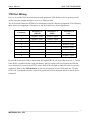
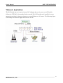
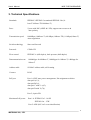
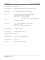
1
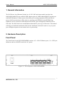
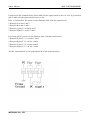
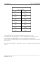
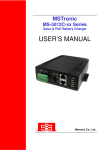
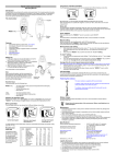
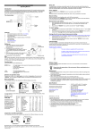
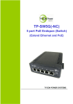
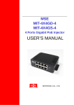
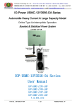
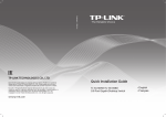
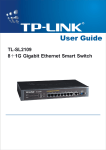
MSE PSE-SW5G44DNR
5 Port PoE Switch & Extender
(Repeat Ethernet and PoE)
AC+DC+PoE TRIPLE INPUT
USER’S MANUAL
MSTRONIC CO., LTD.
User’s Manual
MSE PSE-SW5G44DNR
1. General Information..............................................................
3
2. Hardware Description...........................................................
3
Front Panel…........................................................................................
Rear Panel…..…...................................................................................
Ethernet Port Wiring..............................................................................
PD Port Wiring......................................................................................
Network Application……………………………………............................
3
5
7
9
10
3. Technical Specification………………................................... 11
2
MSTRONIC CO., LTD.
User’s Manual
MSE PSE-SW5G44DNR
1. General Information
The PoE (Power Over Ethernet) Switch is a AC+DC+PoE triple input model, provides four
10M/100M/1000M TX ports with PoE PSE function plus one 10M/100M/1000M TX up-link port
with PoE PD function. It allows power from PoE power souring equipment (PSE) and delivers
power to PoE powered device (PD), which is compliant with IEEE802.3af and IEEE802.3at
standard to receive and deliver both Ethernet data and DC power through the traditional UTP or
STP cable. The PoE Switch can extend Ethernet data and DC power up to 200 meters. This manual
will help you install and maintain the PoE switch. Installation of the PoE switch is very easy and
you will begin to operate as soon as the device is powered up.
2. Hardware Description
Front Panel
The Front Panel of the PSE-SW5G44DNR consists of 5 x RJ-45 Ethernet ports, 12 x LED port
indicators, and one ON/OFF switch (for AC power).
Figure 2-1. The front panel of PSE-SW5D44DNR
3
MSTRONIC CO., LTD.
User’s Manual
MSE PSE-SW5G44DNR
There are 12 LEDs on the PoE switch to indicate the status of power and signal. The following
section describes the functions of each LED indicator.
*POWER LED
LED
Power
STATUS
Description
LED ON when power input (DC IN on
Green
rear panel or Port 5 on front panel) has
valid power supplied.
The indicator is unused on
Red
PSE-SW5G44DNR
Off
No power supplied.
*SWITCH LED (the right indicator on RJ45)
LED
P1~P5
STATUS
Green
Link/Act
Description
A network device is detected (1000Mbps),
but no communication activity is detected.
Green
This port is transmitting to, or receiving
Blinking
package from another device at 1000Mbps.
Yellow
A network device is detected (10Mbps or
100Mbps), but no communication activity
is detected.
Yellow
This port is transmitting to, or receiving
Blinking
package from another device at 10Mbps or
100Mbps.
Off
No device is detected.
4
MSTRONIC CO., LTD.
User’s Manual
MSE PSE-SW5G44DNR
*PoE LED (the left indicator on RJ45)
P1~P4
Yellow
A valid Powered Device (PD) is detected
and delivering power on this port.
PoE
Off
No PD is detected on this port.
Yellow
Powered via all 4 data pairs.
Yellow
Powered via 2 data pairs. (1,2,3,6 or 4,5,7,8
Blanking
are all acceptable).
Off
No power is detected on this port.
P5
PoE
*Rear Panel
The AC inlet, DC input terminal and 2 Ventilation fan are located at the rear panel of the
PSE-SW5G44DNR. The device will work with AC in the range 90-264VAC, 47-63Hz. It will also
work with DC 48V(40V~57V).
Figure 2-1. The rear panel of PSE-SW5D44DNR
All of the PoE switches allow for the possibility to be powered by another PoE source
(42.5~57VDC) on port 5 (UPLINK).
For PoE operation, make sure your power supply offers at least 75W for 4x 802.3af PoE port, or
150W for 4x 802.3at PoE port. If the PSE-SW5G44DNR is not powered in the above designated
input voltage, it will only function as an Ethernet switch without PoE output.
5
MSTRONIC CO., LTD.
User’s Manual
MSE PSE-SW5G44DNR
If powered on DC terminal block, please make sure the input current is not over 10A. If powered on
port 5, make sure the input current is not over 2A.
Ports 1~4 will deliver DC power over the Ethernet cable, with the connection as:
* Data pair A on line 1 and 2
* Data pair B on line 3 and 6
* Data pair C plus V+ on line 4 and 5
* Data pair D plus V- on line 7 and 8
Port 5 may get DC power over the Ethernet cable, with the connection as:
* Data pair A plus V+ /V- on line 1 and 2
* Data pair B plus V-/V+ on line 3 and 6
* Data pair C plus V+/V- on line 4 and 5
* Data pair D plus V-/V+ on line 7 and 8
The DC terminal block on rear panel should be wired as shown below:
6
MSTRONIC CO., LTD.
User’s Manual
MSE PSE-SW5G44DNR
*Ethernet Port Wiring
The PoE switch family supports one RJ-45 uplink (port 5 with PoE PD) and four RJ-45 ports (port
1~4 with PoE PSE) with automatic MDI/MDI-X crossover, auto-sense for the speed and duplex for
10Base-T, 100Base-TX or 1000Base-T connection. Automatic MDI/MDI-X crossover allows you
to connect to other devices (switches, hubs, or workstations etc.), without regard to using
straight-through or crossover cabling.
Port 1 to 4 provides Power over Ethernet function that delivers DC power through the data pairs C
& D (pair 4,5 and pair7,8) to the PD. Port 5 provides Power Device function that receive power
from 4 pairs or 2 pairs Ethernet cable.
The following tables describe the wiring diagram of straight-through and crossover cabling. The
crossover cables simply cross-connect the transmit lines at each end to the receive lines at the
opposite end.
Straight-through Cabling
Pin 1
Pin 1
Pin 2
Pin 2
Pin 3
Pin 3
Pin 6
Pin 6
Pin 4
Pin 4
Pin 5
Pin 5
Pin 7
Pin 7
Pin 8
Pin 8
7
MSTRONIC CO., LTD.
User’s Manual
MSE PSE-SW5G44DNR
Cross-over Cabling
Pin 1
Pin 3
Pin 2
Pin 6
Pin 3
Pin 1
Pin 6
Pin 2
Pin 4
Pin 7
Pin 5
Pin 8
Pin 7
Pin 4
Pin 8
Pin 8
Connect an Ethernet cable into any switch port and connect the other side to your
attached device. The Link/Act LED (green or yellow) will light up when the cable is correctly
connected. Refer to the LED Indicator section for descriptions of each LED indicator.
If a port LED is off, you should check for connectivity problems between that port and the network
device connected.
The maximum cable length for 10/100/1000BaseT with Cat 5 twisted pair cables is typically 100m
(328 ft.).
8
MSTRONIC CO., LTD.
User’s Manual
MSE PSE-SW5G44DNR
*PD Port Wiring
Port 1 to 4 provides PoE injection function with maximum 35W ability to power up the powered
device using the straight-through or cross-over Ethernet cable.
The PoE switch follows the IEEE802.3af Alternative B mode connector assignment. The following
table shows pin assignment of alternative A and B for the Power Source Equipment.
Conductor
Alternative A
Alternative A
Alternative B
(MDI-X)
(MDI)
(All)
1
Negative Vport
Positive Vport
2
Negative Vport
Positive Vport
3
Positive Vport
Negative port
4
Positive Vport
5
Positive Vport
6
Positive Vport
NegativenVport
7
Negative Vport
8
Negative Vport
Be sure the twisted pair cable is bound with the standard RJ-45 pin, especially the pin 4, 5, 7 and 8.
If the RJ-45 is bound with the wrong pin number, the PoE switch will not recognize the PD and
won’t deliver DC power to the PD. The yellow PoE LED will light up when the cable is correctly
connected. Refer to the LED Indicator section for descriptions of each LED indicator. If a port
LED is off, you should check for connectivity problems between that port and the network device
connected.
9
MSTRONIC CO., LTD.
User’s Manual
MSE PSE-SW5G44DNR
*Network Application
The PoE Switch can receive power from a PoE midspan and provide power to the PD which
follows the IEEE 802.3af/at standard in the network. The PoE Switch can be installed in a more
appropriate position for better performance to extend Ethernet to 200 meters. The following figure
is an example of a network application for PoE Switch.
10
MSTRONIC CO., LTD.
User’s Manual
MSE PSE-SW5G44DNR
3. Technical Specifications
Standards
IEEE802.3/IEEE802.3u standards/IEEE802.3ab (10
base-T/100base-TX/1000base-T)
Ports
5 ports with PoE (4 PSE & 1 PD), support auto-crossover &
auto-polarity
Transmission speed
1000Mbps (1000base-T).100 Mbps (100base-TX), 10 Mbps(10base-T)
Auto-negotiation
Switch technology
Store-and-forward
Protocols
CSMA/CD
Flow control
IEEE802.3x (full-duplex), back pressure (half-duplex)
Data transmission rate
1488000pps for1000base-T, 148800pps for 100base-T, 14880pps for
10base-T
Address table
1K MAC address table, self-learning
Connect
RJ-45
PoE port
Port 1-4, PSE auto power management, Pin assignment as below:
data pair A(1,2),
data pair B(3,6),
data pair C with V+(4,5),
data pair D with V-(7,8)
Port 5, 4 pairs PD
Maximum PoE power
Port 1-4: IEEE802.3af – 16.8W
IEEE802.3at – 35W
Port 5: 90W (802.3at 2 event classification)
11
MSTRONIC CO., LTD.
User’s Manual
MSE PSE-SW5G44DNR
PSE disconnect mode
DC disconnect
PoE auto detection
IEEE802.3af & IEEE802.3at (2 event classification signaling)
PoE protection
Over-temperature, over-current, over/under voltage
LEDs
*Link/Activity (Green ON/ Green Blinking @1000Mbps,
Yellow/Yellow Blinking @10M/100Mbps)
*PoE (Yellow)
port 1-4 ON - PD detect
Port 5(UPLINK) ON – 4 pair power, Blinking-2 pair
power
*POWER Green-normal
Power input
*Port 5(UPLINK) from network switch or midspan
*DC input:42-57VDC
*AC input:90-264VAC,47-63Hz,150W max.
Power consumption
8W without PD loading
Power efficiency
75% at full load (@48V typical)
Operating temperature
-20℃~ +85℃
Operation humidity
90% relative humidity, non-condensing
Storage temperature
-55℃~+105℃
Dimension
44mm(H)x210mm(W)x199mm(D)
12
MSTRONIC CO., LTD.