1
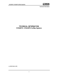
NorthEast Monitoring, Inc. Holter LX Analysis Software International User Guide English Version NorthEast Monitoring, Inc. 2 Clock Tower Place, Suite 555 Phone: 978-461-3992 Maynard, MA 01754 U.S.A. fax: 978-461-5991 www.nemon.com advancing Holter technology Part Number: NEMM028_REV_B_EN Copyright 2010 June 1 ,2010 NorthEast Monitoring, Inc. Software version 5.4a All rights reserved English Version - International User Guide Microsoft Windows XP and Windows Vista are registered trademarks of Microsoft Corp. Java 2 Runtime Environment is a registered trademark of Sun Microsystems. Adobe Reader is a registered trademark of Adobe Systems Incorporated. Special acknowledgement to Bruno Lowagie and Paulo Soares, the authors of iText library. This open source library provided the ability to generate Adobe Acrobat files. For more information, see www.lowagie.com/iText. ****************************************************************************** This product, like all Holter monitoring products, should be used only under the direct supervision of a licensed physician. NorthEast Monitoring FDA Registered Establishment #1224919. The Holter LX Analysis software FDA 510K Market Approval Number K930564. NorthEast Monitoring, Inc. Page 2 Holter LX Analysis 1. Introduction The Holter LX Analysis software comes in five levels - Basic, Enhanced, Enhanced Plus, Pro and Remote (Send). This manual includes instructions for all levels, so some screens and functions included in this manual may not be relevant for your desktop. To see what level of software you have, go to Help > About from your toolbar. a. Package contents NorthEast Monitoring Holter LX Analysis Software CD NorthEast Monitoring License CD NorthEast Monitoring Software Protection Key b. System requirements This software can only be used with a NorthEast Monitoring Digital recorder - the DR180+, the DR200/HE or the SD360. The computer system requirements are: Microsoft Windows XP,Windows Vista or Windows 7 operating systems a processor with a speed of 1 GHz or faster at least 1 GB of memory at least 10 GB of free space on your hard drive a monitor with a resolution of at least 1024 x 768 a USB flashcard reader or a laptop PC card slot a laser printer is recommended. c. Installation Instructions Follow these steps to install the software onto your hard drive: Insert CD labeled Holter LX Analysis into your computer. Open the CD drive, and see list of files to be installed. Click on prompts where appropriate and let the system default during the installation and rebooting anytime it requests. Double-click on 1_SentinelInstall. Double-click on 2_AdobeReader. (If Adobe Reader already exists on your computer, you may want to skip this step.) Double-click on 3_Java_Install. Reboot if prompted to do so. Double-click on 4_LXInstall and follow prompts. On the last screen, make sure that the “Launch Holter LX Analysis” box is checked for installation to complete. After a short delay, the Setup window opens. If you cannot see the Setup window, you should close the CD window for it to appear. When the Setup window appears, you will be able to switch the language of the software. At any time you can get back to the Setup window by selecting the Utilities option of the Holter LX Analysis program. Enter Setup data. Click OK. Remove the software CD and insert the License CD. Open the CD directory and click on the License file. Follow the steps as prompted. Page 3 English Version - International User Guide Plug the software key into an available USB port on your computer and let the system install the software for it. LX Sleep - A special License# is required to view the LX Sleep Apnea software. If you have purchased the LX Sleep license, you will need to install LX Sleep on your desktop by installing the following files that are also found on the CD: Double-click on 5_ Apnea_support_install and Double-click on 6_Apnea_support_DLL d. Formatting a flashcard for the first time Before using a flashcard for the first time, you must do the following: Insert the card into card reader, select My Computer, or with Vista, select Programs > Accessories > System Tools > Computer. In the (My) Computer window, click on the card reader icon and select File > Format. When the window opens, set the File system to FAT, then click Start. e. Initializing a flashcard The flashcard must first be initialized using the LX Analysis software: a. Insert the card into the card reader, and select File > Flashcard > Initialize. The Initialize Memory Card window opens. b. Determine that the correct drive has been selected for your card. If the drive has not been found, check to be sure that a card is in the slot and the reader is attached to the computer. c. Select the appropriate analysis/report type that corresponds to the patient to be hookedup. d. Check to make sure that the correct card format option is selected e. Press Erase. Note: If you insert a card into the recorder and get a message that the “Memory card is missing,” the card is not formatted or erased properly. NorthEast Monitoring, Inc. Page 4 Holter LX Analysis 2. Patient Information a. New Patient To enter new patient information and analyze Holter: 1. Insert flashcard into the card reader and then select File > New. 2. Select the appropriate Type of analysis/report listing from the list and click OK. 3. Type any significant information from the written record manually into the Diary Symptoms window. 4. Click the Start button at the bottom of the Patient Information window. 5. Close Patient Information window and review Holter data. b. Open Patient To see a list of all patients with Holter data, select File > Open. To change the current patient, click on the Patient Name and click Open, or double-click on the line for that patient. You can also use the << and >> buttons on the bottom of the screen to switch patients. c. Patient Information To open the Patient Information window for the current patient, select File > Patient Information. While most of the Patient Information window is the same as that of a new patient, you will see the addition of the Status button, and the Re-analyze button replaces the Start button because the Holter signal has already been analyzed. 6MWA window The Six-Minute Walk Assessment (6MWA) window allows you to enter specific data for 6MWA patients only. A patient is consider a 6MWA patient only if the Patient Type found within the configuration is set to “6MWA”. Otherwise this window is inaccessible. Status window The Status window helps you keep track of the status of each patient’s Holter test. As you complete each step, you can click on the check box next to each field in the Status window to indicate that the step has been completed. If you lock a patient, you will not be able to edit or report on that patient, unless you remove the lock. Page 5 English Version - International User Guide Diary window You can manually enter diary entries here when provided on paper by the patient. Once the recording is analyzed, you will also see events that were created when a patient presses the “Event” button on the Holter recording. d. Preview data on flashcard To review the clerical data on a flashcard, insert card in reader and select File > Preview. The Preview window displays the Patient ID, recorder number, date recorded and the start time on the flashcard. No data is saved on desktop. e. Receive Patients Remotely (Pro and Enhanced Plus) Go to File > Open and press Remote receive button at the bottom of the screen. You will now see the Remote Open Patient window. The Remote Open Patient window has two sections - the top lists all patients that are currently in LX Analysis, the bottom lists all patients who currently exist in the FTP directory that is usually set up as c:\nm\ftp. If you save your incoming records in a different directory, you should enter that now and press the Refresh button at the bottom of the screen. Copy a patient file onto LX Analysis by: Select a blank patient# at the top of the screen by clicking on it Select the incoming patient at the bottom of the screen Press the FTP Copy button. Close the screen and see the Patient Information record for the patient. You can now analyze as you would any other patient. Note: The FTP Delete button is used to delete FTP records after they have been copied into LX Analysis. f. Back-up From the Patient Open window you can go to the Backup screen which allows you to save patient recordings to another location. NorthEast Monitoring, Inc. Page 6 Holter LX Analysis 3. Holter Analysis a. Arrhythmia Analysis Certain analysis and related documentation criteria are already set when you click the Start button in the Patient Information window. They include all the settings that appear in the five windows that are accessible using the Settings button either in the Patient Information window or on the main Holter toolbar. Those windows are What Strips to Auto Save, How Often Strips Auto Save, Scanning Criteria, Spectral Analysis, and Oximetry. What Strips to Auto Save All possible strip labels appear in this window. Each label can be turned off or on to indicate whether sample strips of that type should be saved for the final report. A check mark indicates that sample strips with that label will be saved. How Often Strips Auto Save These settings control the distribution of strips that are saved for the report. Scanning Criteria The Scanning Criteria are used during Holter analysis to define some of the arrhythmias labeled by the software, along with settings that control the amount of information processed. Spectral Analysis Spectral analysis settings for Pro users only. Oximetry Oximetry settings can be adjusted for Oximetry patients. Arrhythmia Re-Analysis Re-analysis is required after changing any of the following in the Scanning Criteria window: Processing, Pacemaker, or Scanning Criteria, Processing modes, Analysis duration, or Extra dead-time. After making a change to any of these settings and clicking OK, the software asks you to confirm whether it is OK to re-analyze. If you want analysis to occur, click Yes. If not, click No. Because re-analysis is required after a change in some Settings, be sure to make any changes to the Settings before you work on the final report. Any bin, template or beat editing, along with manually saved strips and typed comments will be lost after some changes in the Settings. b. Update An Update is required when the settings in What Strips to Auto Save, How Often Strips Auto Save windows, and the Scanning Criteria window - Tachycardia, Bradycardia, SVT and VTAC Page 7 English Version - International User Guide rates; Pause length; Count Irregular HR as Afib; Interval size; and SVPB and VPB prematurity are changed. Any changes to Saved Strips, Tables and Report Summary for the final report should be done after settings are updated, as if done before, they will be lost. Bin, template or beat editing done before the update, will not be lost. Whether the Update button appears in the Review toolbar depends on the “Automatically update tables” setting in the Preferences window. If the software is set to automatically update, the button does not appear; if you must update the data after making changes, the button appears. c. Oximetry Analysis The oximetry data appears in the channel 3 area of all ECG displays. This includes a color-coded (based on the beat label, so usually green) trend of the SpO2 data, with a vertical scale of 60 to 100 percent saturation; artifact in that trend is indicated by vertical hash marks. Pulse oximetry data is displayed as the white trend above the SpO2 trend. In addition, the ST trend in the Trends window shows the oximetry data in two areas - the heart rate data collected appears superimposed on the heart rate trend and the oximetry readings are plotted instead of the channel 3 ST data. Desaturation events are highlighted in red along the oximetry trend. d. ST segment Analysis To review the locations of the ST markers used during analysis, Select Review > Calibration. The ST segment is measured automatically for all three channels of ECG. The data for all three channels is plotted in the ST level display of the Trends window. The ST analysis software looks through the ST level trends, comparing the ST trends to the patient’s baseline trends, to find episodes of significant ST segment changes. In the ST level trends, incidents that are flagged as ST segment events are indicated by a light blue horizontal line above the appropriate channel and lasting as long as the event. The events are listed in the ST event table in the Tables window. All of the information listed in the ST event table can be edited. Control what strips are saved to document ST segment events using a combination of settings in the What Strips to Auto Save and How Often Strips Auto Save windows. e. Pacemaker Analysis Pacemaker activity is recorded on NorthEast’s DR180+ and DR200/HE Digital Recorders without distorting the patient’s ECG, by removing the effects of the pacemaker spike and replacing it with a pacemaker marker. The pacemaker settings in the Scanning Criteria window must be set properly. NorthEast Monitoring, Inc. Page 8 Holter LX Analysis Pacemaker beats can be identified and counted with the following labels: A paced for a beat that is paced just in the atrium. V paced for a beat that is paced just in the ventricle. AV paced for a beat that is paced in both the atrium and the ventricle. Sense failure means that the pacemaker (1) did not sense a QRS that occurred and (2) fired, resulting in a shorter-than-programmed R-to-spike interval. Inhibition refers to inappropriate inhibition of the pacemaker, resulting in a longer-thanprogrammed RR interval. Capture failure means that the pacemaker has fired, but there is no subsequent QRS within the allotted interval. f. 12-lead Analysis If 12-lead data is present on the flashcard, the Holter LX Analysis software activates the 12 Lead menu item in the Review toolbar. If the 12 Lead item is dim, it means that the patient’s Holter recording did not include 12-lead data. LX Analysis allows you to review the 12-lead data on-screen in three different ways - ST Graphs, Strips, and Trends. These three options are listed in the 12 Lead menu in the Review toolbar. 12-lead strips The 12-lead data recorded on the DR180+ is displayed in 12 strips per sample. They are from leads I, II, III, aVR, aVL, aVF, and V1 through V6. In the Strips window, you can choose to display them three leads at a time by clicking the Single button or 12 leads at a time by clicking the Multiple button. In addition to the ECG, the strips appear with either P, Q, R, S and T markers or ST markers (iso-electric, j-point and S), depending on which radio button is selected. Click on the radio button to the left of your choice to change the display range. It can be presented on either a linear or a log scale. g. Spectral Analysis (Pro Level Only) To perform HRV analysis, the software considers only normal-to-normal RR intervals and performs the analysis based on the settings available in Settings > Spectral Analysis. Page 9 English Version - International User Guide 4. Review Methods Depending on what level of software you have, the Holter signal saved for a patient can be reviewed on the monitor of your computer in different ways. You can review and edit: the templates established during analysis (Bin) the most significant events identified during analysis (Critical Events) strips saved for the final report (Saved Strips) on-screen full disclosure of all the ECG (Page) graphs showing the heart rate and RR interval data (Trends) tables compiled for the report (Tables) and superimposition. a. Color coding Throughout the LX Analysis software, the ECG is color-coded based on what the system has labeled each beat: Green: Beats the software has identified as normal. Yellow: Beats identified as supraventricular premature beats (SVPBs). They have a normal morphology, but fall early. Red: Beats identified as ventricular premature beats (VPBs). They differ significantly from the normal; they are not necessarily premature. White: Beats identified as pauses, based on the definition in the Scanning Criteria window. The white overrides any other color that the beat may also qualify for (e.g., red because it is a VPB). Light blue (cyan): Signal that appears to be contaminated by artifact. Cobalt blue: Beats identified as paced. All data must be reviewed carefully to ensure that you agree with the beat labels the software has selected; if you do not agree, you can change them and their color will change appropriately. b. Labels In addition to the color-coded labels the software provides for each beat, there are some labels only you can use to relabel beats. These are: Aberrant: Use this label to identify and counts beats as aberrantly conducted SVPBs. All matches to the template that meet the SVPB prematurity requirement will be counted as Aberrant SVPBs and colored yellow, like the other SVPBs. NorthEast Monitoring, Inc. Page 10 Holter LX Analysis Questionable (Unknown): Use this label to separate out beats you cannot identify and keep them from being included in another category. They are colored green, like normals. T-wave: Use this label if the software has identified a portion of the signal as a QRS, but it is not. This will remove the beat from the counts and will merge its RR interval with the preceding RR interval. c. Measure ECG data The data fields in the center of the toolbar - HR (2 RR), Time, and the ST indicators for each channel - contain data calculated based on the two blue calipers in the active strip. As you drag the blue calipers, those fields change, reflecting the new caliper positions. To measure a two-beat heart rate, place the calipers two RR intervals apart; the measurement appears in the HR (2 RR) field. To measure ST in any of the channels, position the left caliper in the isoelectric area of the PR interval and the right caliper where you want to make the ST measurement; the measurements for each channel appear in the appropriate fields. To move the calipers keeping them the same distance apart, click the check box next to Both and then drag the calipers. Click again to remove the mark and move them separately. To keep the calipers in the same locations as you move through different screens of ECG, click the check box next to Lock; the calipers will stay in the indicated locations unless you move them again. Click again to turn off. To make ST measurements, place the left caliper in the isoelectric portion of the PR interval, and place the right caliper where you want the ST segment measurement to be made; the vertical distance between where the left caliper intersects the ECG and where the right caliper intersects the ECG will appear in the ST field for each channel (labeled ST 1, 2, 3). d. Time-of-Day All review windows are linked by time-of-day. In addition, the Page window is linked to all other review windows through the right-hand button on the mouse. From any other review window, a right-click will jump to the Page display, retaining the current beat. After that, a rightclick in Page will then take you back to where you originally were, regardless of whether you change the current beat in the Page window. Page 11 English Version - International User Guide e. Bin Screens The software determines what the patient’s normal QRS complex looks like and establishes a template called “normal.” Each beat after that is compared to the normal template; matches to that template are also called normal, while a similar but slightly different morphology will establish a new template, also called normal. A QRS complex that differs more significantly from the normal template will establish a template called “ventricular.” A new template is established for each different morphology identified by the software. Subsequent matches to a template are labeled based on the template label, the timing of the beat, and other criteria. After analysis, the templates that generally look alike are grouped together in “bins.” You can review these bins by morphology, that is, all normal bins or all ventricular bins. Within the Bin window, you can also review by template, displaying all the templates within each bin. To change the morphology displayed, click on the arrow in the Morph field to display your choices, and then click on the type you want displayed. To undo a relabel, click the Undo button. It will restore the templates to their state before the last relabel. The template display contains up to 12 templates that matched the current bin. If more than 12 templates fell into that bin, you can access additional pages of templates by using the Page Down key, the scroll bar or the Scan button Clicking the Beats radio button displays up to 24 of the beats that matched the current template. Use the Page Down, the Scan button, or the scroll bar to display additional matches to the template. f. Critical Events Screen Each type of critical event has a number associated with it - the number of events of that type that were identified for this patient. Every event of each type can be displayed, either one at a time (full-sized) or 12 at a time (miniature). A beat that appears in one category of Critical Events does not appear in all other applicable categories. For example, if a VPB appears in Bigeminy, it does not appear in VPB; if a paced beat appears in Sense Failure, it does not appear in any other paced category. Therefore, do not rely on the counts in Critical Events to provide comprehensive totals. Histograms The top portion of the Critical Events window presents a histogram showing the distribution of the events within the type displayed - either an RR histogram or a 24-hour histogram. Relabel in Critical Events All relabeling done in the Critical Events window is single-beat editing. To relabel a beat within the Critical Events window, click on the event to select it; this turns the relabel buttons from dim to colored. Click one of the colored relabel buttons to relabel the selected beat. NorthEast Monitoring, Inc. Page 12 Holter LX Analysis g. Saved Strips Screen The report includes full-size, 7.5-second, 25-mm/sec strips on a background grid. Some strips are automatically saved based on the settings in the What Strips to Auto Save window. You can also use the Keep button to manually save strips while reviewing the Holter recording. Review Saved Strips To review the saved strips, click Saved Strips in the Holter menu. The Saved Strips window displays a miniature version of the strips 12 at a time. Each is labeled with its strip label and the time-of-day at which it occurred. Page through them using the Page Up and Page Down keys, the up and down arrows of the scroll bar, or the scroll button on your mouse. All strips are three-channel unless oximetry data was collected for this patient; if oximetry data is present, it appears in the area where channel 3 normally appears, and data fields of SpO2 data appear to the right of the standard data fields. The strips are initially sorted by strip label. To review them ordered by time-of-day, select Time from the choices in the Sort field. ST event labels include the channel in which the ST segment change occurred. Change the active strip At any time, there is only one active strip, the strip outlined in blue. Four fields above the strips refer specifically to the active strip. Those fields include time-of-day, a strip number, HR (heart rate) and HR2 (the second heart rate, that is, the heart rate of a run of VTAC or SVT in the strip). To change the active strip, click on the one you want so that the outline surrounds it. You can also change the active strip by clicking the List button in the toolbar to open the List window. The List window lists each strip label and corresponding heart rate in order of time-of-day. To display a particular strip from the list, click on the appropriate entry on the list and click OK, or double-click on the entry. To exit without changing the active strip, click Cancel. Edit a strip label To change the label of the active strip, click on Edit in the toolbar. The Edit window opens; it includes a field with the current label of the strip and the heart rate of the ECG in the strip, along with the second heart rate, the rate of either SVT or VTAC if it is present. (A second heart rate of 0 indicates that there is no run on the strip.) Delete a strip To delete one strip in the Multiple strip display, click on it to make that strip the active one, then click Delete in the toolbar. To delete more than one strip, click on the first strip to make it the active strip; in addition to the blue highlight around the strip, there is also a yellow highlight around the time-of-day, indicating that the strip is selected. Click on any additional strips you want to delete, then click Delete in the toolbar. All of the selected strips (as indicated by the yellow highlight) are now deleted. Page 13 English Version - International User Guide When you delete a strip, its label becomes red; strips with red labels are not included in the printed report. To retrieve a deleted strip, click on it and then click Delete in the toolbar again. To delete all of the strips displayed, click the button labeled Del/Undel All. To retrieve all of the strips displayed, click the button again. To delete only one or more channels of a strip, click on a strip to make it active. Then, click on one of the check boxes labeled Channel 1, 2 and 3 to delete it. Alternative strips Some strips can be replaced by an alternative: maximum and minimum heart rates, shortest and longest RR intervals, and fastest and longest runs of VTAC and SVT. If you would prefer to select a different alternative, click on the strip to make it active and the Alternatives button appears. Click the Alternatives button to make the Alternatives window opens, displaying other choices for that label. To select a different strip, click on the strip and then the Select new Alternative button. Expand the active strip To view a strip more closely, either click Single in the toolbar or double-click on the strip. It then fills the Saved Strips window. Each beat is labeled with either the heart rate (BPM) or the length (in milliseconds) of the RR interval following the beat. Saved Strips are re-compiled after every update or re-analysis, so be sure to make changes to the automatically saved strips only after you have completed all other editing. Any editing of automatically saved strips that occurs before an update or re-analysis will be lost. Manually saved strips remain as is. NorthEast Monitoring, Inc. Page 14 Holter LX Analysis h. Page Screen The Page window allows you to review all of the ECG stored during the recording, like an electronic full disclosure. The window is divided into two displays: a miniature, single-channel presentation and an expanded three-channel display with a background grid. Use the Full screen/Expand button to toggle between the miniaturized ECG and a combination screen formats. Single-channel page display The single-channel page display contains a blue highlight box surrounding one of the QRS complexes, the “current” beat. The time-of-day at that beat is displayed in the time field in the upper left corner of the window. The displayed ECG can be adjusted in these ways: To adjust the ECG so that the highlighted beat appears in the center of the page, click Center. To move the highlight box to a different beat, click on the beat. To change the channel displayed, click on the Lead field and select a different channel from the list. To change the amplitude of the displayed signal, click on the Gain field and select a different size from the list. To change the amount of time displayed on each page, click on the Zoom field and select a different amount of time. In the single-channel display, you can visually review pages of ECG by using the Page Up and Page Down keys, by clicking on the down arrow of the scroll bar, by using the scroll button on your mouse, or by clicking the Scan button. Turn the Scan button off by clicking it again. Control the speed of the scan by pressing + to make it faster and - to slow it down. Expanded ECG display The expanded display shows three channels of ECG in the bottom of the Page window. To display expanded ECG, click the Expand button. The expanded ECG in the bottom half of the window and the single-channel display in the top half of the window are linked. The expanded strip is centered on the highlight box in the top half. If you move the highlight box, the ECG displayed in the bottom half changes appropriately. If there is oximetry data for a patient, it appears in the Channel 3 area of the expanded ECG. The color-coded trend (mostly green) shows the SpO2 data and the white trend shows the pulse waveform. Relabeling in the Page display The type of relabeling performed is determined by the setting in the Mode field: Single beat relabels just the current highlighted beat to whatever label you choose. Page 15 English Version - International User Guide All matches relabel the template to whatever label you choose. To relabel in the Page window, click on the beat to be relabeled, select the appropriate setting for the Mode field, and then click the appropriate relabel button. To relabel multiple single beats to the same label, click on the first beat, then press the Shift key and click on each additional beat. A blue highlight box surrounds each of the beats to be relabeled; click the appropriate relabel button. To relabel a string of beats to the same label, click on the first beat and then drag across to the last beat; the beats turn magenta. Then click the appropriate relabel button. Whenever you use a relabel button, a message appears in the bottom strip of the window indicating what label was given to the beat and how many beats were relabeled. In addition, error messages appear there whenever you try to relabel inappropriately. Turning Afib On/Off If a patient is in intermittent atrial fibrillation or flutter, you can disable the SVPB counts and relabel that region as Afib. To do so, select the ECG by dragging across it (it turns magenta), then click the Afib On button. All the selected beats turn green, indicating that they are relabeled as Afib and not SVPB. Insert a beat If while you are reviewing the ECG in the Page window, you see that a particular beat is included in the highlight box of the preceding beat, it means that the beat was missed. This is usually because of very low amplitude, but sometimes because of low slope. To force the system to count the beat, you can use the Insert button in the expanded Page toolbar. To insert a beat, first click near the beat so that it appears in the expanded Page display, then drag or click the left-hand caliper to the location of the missed QRS complex. Click the Insert button in the toolbar in the middle of the window. The Insert window opens, with the time-ofday of the new beat listed in the first field and a beat label in the Morphology field. Click on the arrow in the Morphology field to display the list of label choices and make your selection. Then click OK to insert that type of beat where the left-hand caliper is. Save strips for report To save a strip, click on the beat you want at the center of the strip to move the highlight box there, and then click the Keep button; the Keep window opens. The Description field contains the current beat label. To relabel the strip, either type the label in the Description field or select a label from the scrolling list. Click OK to save. The Keep window includes two heart rate fields: HR, which equals the heart rate of the background rhythm of the strip, and HR 2, which is the rate of the run (VTAC or SVT) on the strip, if there is one. Both fields can be edited. NorthEast Monitoring, Inc. Page 16 Holter LX Analysis To save strips of an event longer than 7.5 seconds, drag the cursor across the ECG to be saved (the selected ECG turns magenta) and then click Keep. In the Keep window, you can enter the label of the first strip in the series and then click the left button, which indicates how long a time period to be saved. To save multiple strips, all with the same label, click on a beat at the center of the ECG to be saved, then hold the Shift key down and click on another beat. Then click Keep. In the Keep window, click the button labeled “n strips” to save all the selected examples; click the button labeled “1 strip” to save just the first. i. Trends Windows For Basic and Enhanced Levels, the trends present data in 30- or 60-second increments throughout the Holter period, including an RR trend showing the range of RR interval measurements in each minute and an HR trend showing the average heart rate for each minute. The trend also includes oximetry data, if it was collected while recording. On all of the trends, time-of-day appears on the horizontal axis. RR intervals are plotted so that the range within each minute appears as a vertical line; the top end of the line indicates the longest RR interval within that minute, and the bottom of the line indicates the shortest RR interval within it. The blue marker The blue vertical marker is located at the time-of-day of a particular 30-second segment. Click on either trend to move the marker to a different time-of-day. The time-of-day that appears in the large data box indicates the time-of-day at the marker. The data boxes at the top of the display indicate the data collected for the minute where the marker is located, including heart rate (HR), the shortest RR interval (RR Min), the longest RR interval (Max), the total number of VPBs and SVPBs, and the total number of VPBs and SVPBs that occurred during runs of VTAC and SVT. In addition, the ST data boxes include data collected for the 30-second interval where the marker is located, including the ST segment measurement for each channel in ST 1, 2 and 3, and the ST slope measurement for each channel in Slope 1, 2 and 3. Asterisks indicate that there is no data for that time period, usually because of artifact. The oximetry data appear with the measured heart rate in the SpO2 HR field, the minimum SpO2 measurement in the Min field, and the maximum SpO2 measurement in the Max field. For Oximetry patients, a SpO2 derived HR trend is also visible in dark blue on all trend screens. Relabel to Artifact In the Trends window, to relabel a continuous period as artifact, click at the time-of-day you want to start rejecting and then drag until the end time. The time period turns magenta. Now click the Artifact button. On the Oximetry Screen, artifact will be applied to the Oximetry trend. On all other screens, the HR trend. Page 17 English Version - International User Guide General Trends (Enhanced Plus and Pro Levels) The general trends present data in one-minute increments throughout the Holter period, including the RR trend showing the range of RR interval measurements; the heart rate trend showing the average heart rate; total VPB and VTAC trends; and total SVPB and SVT trends. ST Trends (Enhanced Plus and Pro Levels) The ST trends present the ST segment analysis data in 30-second increments throughout the Holtered period for all three channels of data. The placement of the ST calipers is automatic unless you re-set them in the Calibration window. The ST trends include three components for each channel: (1) the patient’s baseline ST measurement, that is, the patient’s normal ST; (2) the actual measurement made for each 30-second increment; and (3) the slope indicator for each 30-second indicator. The baseline measurement is trended as a blue line, the actual measurement is green, and the slope indicator is a vertical red line drawn from the actual measurement to the measured value at the slope caliper. Oximetry Trends For patients with oximetry data, you can access the Oximetry Trend Screen. The trend labeled SpO2 contains oximetry data, including (1) a color-coded trend line (colored the same as the beat labels) of SpO2 data on a scale from 60 to 100 percent saturation and (2) a white trend showing pulse oximetry data. On this screen, you are able to artifact oximetry, turn On and Off Desat(uration), and run Sleep Apnea, if you have the capability. To create a new desaturation event, drag across the Trend window from the beginning of the event to the end. The trend is highlighted in magenta. Press Desat On to identify that period as a desaturation event; the event is automatically entered in the Desaturation table in the Tables window. Sleep Apnea If LX Sleep is enabled, you will be able to determine the AHI (Apnoea–Hypopnoea index) for your Oximetry patient. You can calculate AHI by dragging across the trend and turning On or Off time that should be included in the analysis, and then press Run Apnea. NorthEast Monitoring, Inc. Page 18 Holter LX Analysis j. Tables Window To review the tables compiled for a patient, click Tables in the Review toolbar. The listing of what tables are available appears at the right of the screen. The displayed table is highlighted in blue. To display a different table instead, click on its name in the list. Within the Interval Table Edit window, you can click in any editable data field to type in your changes. Highlight an existing entry and type over it, or click to the right of the entry and backspace to eliminate it and then type your entry. To eliminate information within an interval, use the Zero All buttons to zero out the day or enter a zero into each field you want to remove. k. Additional features Superimposition Select Superimposition from the drop-down Review menu. Click on Scan to start and stop the superimposition display. Control the speed of the scan by repeatedly pressing + to make it faster and - to slow it down. Calibration Adjustment Select Calibration from the drop-down Review menu. Three channels of calibration signal are displayed. The two horizontal lines for each channel should be lined up so that one is level with the top of the square wave and one is level with baseline. Drag the lines to move them. To increase the size of the signal for analysis, set the horizontal gain markers close together. To decrease the size of the signal for analysis, set the horizontal gain markers far apart. If you use the gain markers in this way, the signal is no longer calibrated and no ST measurements are correct. Invert/Hide To invert the signal in a channel or to hide it from view go to Review > Invert/Hide. Click on the check box for each channel to be inverted or hidden; click on it again to return the signal to normal. Shorten analysis time To shorten the analysis time, move the marker to the time-of-day at which you would like to end analysis, then select Review > Shorten analysis time. Page 19 English Version - International User Guide 5. Reports To access the report modules, select Reports from the Review toolbar. The modules that are available for the current patient are listed in the right half of the Reports window. To include a module in the report, the check box next to the module name in the Reports window must contain a check mark. Click on an empty box to add a check mark, and click on a check mark to remove it. To turn all of the modules on or off, click on the All On/Off check box under the report module list; to change them all again, click on the All On/Off check box again. Report heading The Patient Information module includes a Report heading so that you can customize the report for your facility. To enter text in a line, click on the field and type your entry. If your address comes up automatically, but you would like to change it for a particular patient, you can either make your selection from the addresses you have associated with different report configurations or you can edit it on this screen. Saved strips If the final report includes either half or full-sized strips, it will include only those strips designated in the Saved strips field of the Reports window. To include just the automatically saved strips, open the Reports window and select Automatic in the Saved strips field. To include just the manually saved strips, select Manual for that field. To include both types, select Both. Strip annotation In the Reports window, set the Strip annotation field to indicate how you would like the beats annotated. The beat labels consist of: N for normal S for SVPB V for VPB A for artifact P for paced (A, V, or AV) E for aberrant SVPB D for event marker ? for questionable/unknown Report summary The summary that prints on the front page of the report can take one of five different formats. NorthEast Monitoring, Inc. Page 20 Holter LX Analysis To view and/or edit the summary on-screen before printing the report, make your selection in the Report summary field and then click the View summary button in the bottom of the Reports window; this opens the appropriate Report Summary window. Edit the Report summary When you click on View summary, the Report Summary window displays the information exactly as it will appear on the front page of the report. Every character can be edited, if you choose to do so. You can select the text and then delete it or type over it or you can simply add to the information that is already there. To add comments to the end of the summary, click after Comments: and then either type the comment or select a line from the Phrases window in the left portion of the window; after selecting the phrase, click Add to copy it over into the Comments area. The Phrases list appears only if you entered at least one sentence in File > Preferences > Summary phrases. To access the additional Comment window, click the Comment tab at the top of the window, then type the information you would like to appear on the Comments page of the report (typically page 2). Click the Summary tab at the top of the window to return to the previous Report Summary window, the one that appears on the front page. If you start making changes to the text in the Report Summary window, but then decide you would like to revert to the original information, click the Reset button; your changes to the Report Summary window will be deleted and the text will return to the original. Status indicators Use them to keep track of whether a patient’s Holter has been edited, printed, and/or verified already. Click the check box to add or remove a check mark. Full disclosure Full disclosure is a printout of all the ECG recorded during the Holter monitoring period, in a miniaturized format. Each page is annotated with time-of-day along the left margin. Update the Full Disclosure of the Report screen to customize what and how the full disclosure appears. Review To review the report on screen before printing it, click the Review PDF button at the bottom of the Reports window. This launches the Adobe Reader program that generates a PDF file for you to review on-screen. The report cannot be edited or changed in any way in this display mode, but you can go back to the Review methods (Bins, Critical Events, Saved Strips, Page, and Trends windows), or to the Report Summary or the Patient Information window to make changes before saving and printing the final report. Print Print your report in Adobe after reviewing. Page 21 English Version - International User Guide 6. Preferences & Configurations a. Preferences window To open the Preferences window, select File > Preferences. These customization options are available, depending upon the software level. Preferences do not exist in the Basic or Remote versions. Draw grid You can choose whether there is a background grid behind the expanded strip displayed in the Page window. A check mark indicates that a light grid will appear. No check mark means that the grid will not appear. Use large fonts This determines the size of the font used throughout the software. Display toolbar Toolbar will be displayed if this is checked. If not checked, use Review to navigate screens. “Print Screen” in color If you have a color printer and want to print out screen displays in color, turn this setting on. Use Control Panel vs. dd-mmm-yyyy date format To use the date format used throughout your computer system instead of the format provided by this software. Read flashcard information on Patient/New If this setting is off, the data on the flashcard is not read until you click the Copy flashcard button in the Patient Information window. If this setting is on, you must insert the flashcard into your computer’s card reader before a new patient record can be opened. If you select File > New without first inserting the card, you will not be able to continue for this patient until the card is inserted. Save new Physician or Interpreting physician This field allows the software to ask you whether to add a new physician or interpreting physician name to the appropriate list when you close the Patient Information window after typing a new name in either field. NorthEast Monitoring, Inc. Page 22 Holter LX Analysis Automatically update tables A check mark should appear in the check box so that the software automatically updates counts, tables and strip labels after you relabel a beat, template or bin in any of the Review windows. If it does not automatically update, you must manually run an update after making changes. Confirm T-wave/Supraventricular “Single Beat” relabel Relabeling a beat to a T-wave or SVPB can only be performed at the Single beat level, regardless of the Relabeling Mode setting in the Page window. When you relabel a beat to one of these, the software can remind you that only a single beat is being relabeled. Annotation Indicate here whether the beats in any on-screen, expanded strip should be labeled with a beatby-beat heart rate calculation or RR interval length. ST measurement Set your preference for ST measurement here. After analysis show This field allows you to determine which window is displayed upon the completion of analysis. Print countdown This button is not functional. b. Edit fields Entries in those fields can be preset so that you can make a selection from a list instead of typing the physician name in for each Holter test. Physician and Interpreting physician names To add a name to the list in the Physician field of the Patient window, go to File > Preferences > Physicians to add, edit or delete the physician names. Summary phrases You are able to customize entries for the Comments area of the Report Summary section of the printed report using this button. Page 23 English Version - International User Guide c. Running the Configuration program Access the Configurator with the Holter LX Analysis program running via the File > Preferences window. Default Configurations Four default configurations – Holter, Oximetry, Sleep and 6MWA (Six-Minute Walk Assessment) - cannot be changed and have been set up for you to copy to build your own customizable configurations. All but the Holter default configuration can be deleted if you so choose. They can be brought back later by clicking the “Restore” button. Configuration window Once set up by you, the main Configuration window opens with a listing of all current configurations of your software. Each should have a unique name. To make changes, you can either edit an existing configuration or create a new one. You can also delete a configuration if you no longer need it. To Create a Configuration To create a new configuration, click on the name associated with a configuration similar to the one you want to create, and then click the Copy button. Configuration folders The window for a specific configuration consists of a pile of folders with tabs. Each folder contains the controls for a particular window or portion of the Holter LX Analysis software. Within the folders for a configuration, any entry in any of the fields automatically appears whenever you create a new patient using that configuration. To display the fields in a particular folder, click on the tab for that folder. Changing or Adding a configuration For each configuration you create or edit, make changes in as many folders as you need to. When all folders reflect what you want to associate with that configuration, click the OK button at the bottom of the window. Your new configuration will be saved and the window closed; the main Configurator window then appears. Cancel a configuration To exit without saving the new configuration, click Cancel. The window closes and the main Configurator window appears. Exiting from the Configuration program To exit from the Configuration program, click on the red Close button in the upper right corner of the window. NorthEast Monitoring, Inc. Page 24 Holter LX Analysis Using a configuration The configurations created or edited using the Configurator appear when you start a new Holter test and when you initialize an SD card. When you select File > New to open the Patient Information window for a new Holter test, a list of the Configuration descriptions appears in the Type of analysis/report field; select your choice from that list. When you initialize an SD card before a recording, the list of DR200/HE Configurations appears in the DR200/HE settings field of the Setup DR200/HE settings window; select your choice from that list. If you use an inappropriate configuration for a patient, after analysis, you can always go to the appropriate Settings windows and make necessary changes; the system will automatically update or re-analyze as needed, but keep in mind that any changes you made to the previous settings and any editing you already have done to the recording will be lost and have to be redone. Page 25 English Version - International User Guide 7. Remote Send The Remote Send software is not supported in version 5.4. If you choose to send files using this software, you must use version 5.3d or earlier. The LX Analysis Remote utility allows you to send Holter data to another site for analysis. You can use 1) MagicVortex, 2) FTP, or 3) Direct Copy, or 4) Run External FTP to send files. A computer technical professional is required to set up most of the other methodologies discussed below. If this support does not exist in your organization, we recommend using MagicVortex to send Holter data. a. Set up To access Remote Settings: Access Remote when the LX Analysis program is not running. To run Remote, go to Start > Programs > Holter LX Analysis > Remote. From the Start menu, select Programs > Holter LX Analysis > Remote to start the Remote software. Go to Remote > File > Settings and the Remote Settings window will appear. Now you can set up which option your organization has chosen. Option 1: To Set Up MagicVORTEX Become a MagicVortex Subscriber To sign up for MagicVortex, visit their web-site at www.MagicVortex.com and select Sign up from the menu on the home page. Once you are set up, the MagicVortex icon on your desktop should contain a blue center indicating that you are currently connected to the MagicVortex. If the center of the MagicVortex icon is gray, you are not currently connected to MagicVortex via the Internet and you will not be able to send patient data until the connection is established. Set up MagicVortex in LX Analysis for Sending files 1. Click on the MagicVortex box to enable. The Directory field should read c:\nm\ftp. If it does not, click on that field and correct. 2. Click on the “To email address” and type the e-mail address where you are sending the Holter data for analysis. NorthEast Monitoring, Inc. Page 26 Holter LX Analysis Option 2: To Set up FTP FTP stands for File Transfer Protocol and is a commonly used methodology for exchanging files over any network that supports the TCP/IP protocol. You will need an in-house technical professional to assist you in setting up your infrastructure: 1. Click on the FTP box to enable. 2. Fill in all of the fields in the FTP fields as instructed by your technical professional. Option 3: To Set up Direct Copy You can also send patient data via an internal network to another computer. Go to the Remote Settings screen and: 1. Click on the Direct Copy box to enable. 2. Enter the Directory with the location to where you want to send the file. Option 4: To Set up External FTP 1. Click on the Run External FTP box to enable. 2. Fill in the Command line as instructed by your technical professional. b. Additional Features Email notification Fill in the Mail box if you would like to notify the receiver when you have sent a file. Your technical professional will need to provide you with your Mail Server location. Send Location Click on the Location field. This entry is used to rename the patient files you send so that there is a unique filename at the receiving site. If you have been assigned a location name by the receiving site, type that. If not, type something to identify your location. Send Initials Enter your initials to further identify your files. Type of Analysis/Report Your receiving site will instruct you on what to enter in this field. c. Sending Patient data From the Start menu, select Programs > Holter LX Analysis > Remote to start the Remote software. Page 27 English Version - International User Guide For a new patient 1. For a New Patient, select File > New to open a patient slot for the patient to be sent. If no empty slot is available, the Open Patient window opens and you must delete one of the patients on the list; then close the Open Patient window and select New again. 2. When the New Patient window opens, select an appropriate Type of analysis/report, and then click OK. The Patient Information window opens. 3. Insert the flashcard from the recorder into the flashcard reader. 4. Click the Copy flashcard button in the Patient window. This copies the Holter data from the flashcard onto your computer’s hard drive. Some of that data appears in the Patient window; verify that the data from the flashcard is for the correct patient. 5. Enter additional patient information you want included in the final Holter report, including any written diary entries, indications and medications. 6. When you have completed the fields, click Remote. 7. The Remote Screen will now open. 8. The New Patient that you set up should be highlighted. You can highlight any other patients at this time by pressing the Ctrl key while clicking on additional patient records. 9. Once you have selected the patients you want to transfer, Click Link at the top of the screen. (To exit without sending the data now, but saving your entries, click OK. To exit without sending or saving, click Cancel.) 10. When the transfer is initiated, the Link status window will appear and give you an update on the transfer. If it is a large transfer, you can minimize the screen by clicking on the button. You will also see a small Message window with the status of the transfer. 11. Once the transfer is complete, the STOP button will read Success and a new window with the transferred file name is displayed. 12. Note that the Link screen will now show the time and date at the top of the screen of the transfer. The list of transferred patient records for this session is also displayed. Close this screen and you are returned to main screen in Remote or the Patient Information screen for the new patient. 13. Be sure to click on OK on the Patient Information window so that all of the data will be saved Note: If you are saving new patient data, you must click OK when you return to the Patient Information screen. If you do not click OK and close the screen, the new patient information is not saved on your system. For one or more existing patients For an existing patient, Select File > Patient Information > Remote. You will now see the Remote Patient Window with the current patient highlighted. You can now select additional patients by holding the Ctrl key while highlighting additional patient records. Once you have selected the patients you want to transfer, Click Link at the top of the screen. Now continue with Step 10 above. NorthEast Monitoring, Inc. Page 28 Holter LX Analysis 8. Utilities You should access the Utilities when the LX Analysis program is not running. To run Utilities, select Start > Programs > Holter LX Analysis > Utilities. The NorthEast Setup Window appears. Setup Window The Setup window contains the following information that you can update: The name of your facility The primary user of the Holter software Five lines for the name and address that appear automatically in the Reports window The language that the software uses The number of patient stored in the software. Note: If you choose to change the number here in the Setup window, all patient directory slots are overwritten with empty new patient slots, so be sure any patients whose reports are overwritten are already backed up before you proceed. Page 29