1
Quick Check® SV Series
Bar Code Scanner/Verifier
™
User’s Guide
Disclaimer
Hand Held Products, Inc. (“Hand Held Products”) reserves the right to make
changes in specifications and other information contained in this document
without prior notice, and the reader should in all cases consult Hand Held
Products to determine whether any such changes have been made. The
information in this publication does not represent a commitment on the part of
Hand Held Products.
Hand Held Products shall not be liable for technical or editorial errors or
omissions contained herein; nor for incidental or consequential damages
resulting from the furnishing, performance, or use of this material.
This document contains proprietary information that is protected by copyright. All
rights are reserved. No part of this document may be photocopied, reproduced,
or translated into another language without the prior written consent of Hand
Held Products.
© 2001-2005 Hand Held Products, Inc. All rights reserved.
Web Address: www.handheld.com
Statement of Agency Compliance
This device complies with part 15 of the FCC Rules. Operation is subject to the
following two conditions: (1) this device may not cause harmful interference, and
(2) this device must accept any interference received, including interference that
may cause undesired operation.
FCC Class B Compliance Statement
This equipment has been tested and found to comply with the limits for a Class
B digital device pursuant to part 15 of the FCC Rules. These limits are designed
to provide reasonable protection against harmful interference in a residential
installation. This equipment generates, uses, and can radiate radio frequency
energy and, if not installed and used in accordance with the instructions, may
cause harmful interference to radio communications. However, there is no
guarantee that interference will not occur in a particular installation. If this
equipment does cause harmful interference to radio or television reception,
which can be determined by turning the equipment off and on, the user is
encouraged to try to correct the interference by one or more of the following
measures:
• Reorient or relocate the receiving antenna.
• Increase the separation between the equipment and receiver.
• Connect the equipment into an outlet on a circuit different from that to which
the receiver is connected.
• Consult the dealer or an experienced radio or television technician for help.
Caution: Any changes or modifications made to this device that are not
expressly approved by Hand Held Products, Inc. may void the user’s authority
to operate the equipment.
Note: To maintain compliance with FCC Rules and Regulations, cables
connected to this device must be shielded cables, in which the cable
shield wire(s) have been grounded (tied) to the connector shell.
Canadian Notice
This equipment does not exceed the Class B limits for radio noise emissions as
described in the Radio Interference Regulations of the Canadian Department of
Communications.
Le present appareil numerique n’emet pas de bruits radioelectriques depassant
les limites applicables aux appareils numeriques de la classe B prescrites dans
le Reglement sur le brouillage radioelectrique edicte par le ministere des
Communications du Canada.
The CE mark on the product indicates that the system has been tested to and
conforms with the provisions noted within the 89/336/EEC Electromagnetic
Compatibility Directive and the 73/23/EEC Low Voltage Directive.
The CE mark on the product indicates that the system has been tested
to and conforms with the provisions noted within the 89/336/EEC
Electromagnetic Compatibility Directive and the 73/23/EEC Low
Voltage Directive.
For further information please contact:
Hand Held Products, Inc.
Nijverheidsweg 9
5627 BT Eindhoven
The Netherlands
Hand Held Products shall not be liable for use of our product with equipment
(i.e., power supplies, personal computers, etc.) that is not CE marked and does
not comply with the Low Voltage Directive.
SV Series Use with UL-listed Equipment
The SV Series should be used only with printers, applicators, conveyors, etc.
that are UL listed.
Cautions
•
•
•
•
Never stare directly into the laser beam.
Never stare directly at a reflected image of the laser beam.
Avoid exposure to the laser beam.
Use of controls or adjustments or performance of procedures other than
those specified herein may result in hazardous radiation exposure.
Laser Beam
The laser beam may be on at any time the Power/Sync LED is illuminated.
Table of Contents
Chapter 1 - Quick Check SV Series
Introduction........................................................................... 1-1
SV Series Model Specifications .......................................... 1-2
ScanView Software .............................................................. 1-2
Chapter 2 - Control Panel
Reset Button.......................................................................... 2-1
Turn Off Laser Beam ..................................................... 2-1
Perform Calibration........................................................ 2-1
Reset Ports...................................................................... 2-1
I/O Connector ...................................................................... 2-1
+ 5 VDC Power Input ........................................................... 2-2
Sync Inputs ........................................................................... 2-2
Edge Sync Mode ............................................................ 2-3
Envelope Sync Mode ..................................................... 2-3
Communication Sync Commands ........................................ 2-4
Output Ports .......................................................................... 2-4
System Displays.................................................................... 2-4
Power/Sync LED............................................................ 2-4
Calibration LED ............................................................. 2-4
Read LED....................................................................... 2-5
Indicator LEDs 1 and 2 .................................................. 2-5
Chapter 3 - Serial Port Connector
Serial Port Specifications...................................................... 3-1
Serial Port Pin-out................................................................. 3-1
Serial Port Transmission Format .......................................... 3-1
Chapter 4 - ScanView Installation and Setup
Introduction........................................................................... 4-1
System Requirements ........................................................... 4-1
ScanView Software Installation ........................................... 4-1
PC Communication Port Setup............................................. 4-2
i
Software Operation Warnings .............................................. 4-3
Title Bar – Screen Display.................................................... 4-3
Menu Bar – Screen Display.................................................. 4-3
File Menu ....................................................................... 4-3
Setup Menu .................................................................... 4-3
Advanced Menu ............................................................. 4-5
Support Menu................................................................. 4-5
About (Menu Item) ........................................................ 4-5
Speed Button Bar – Screen Display...................................... 4-6
Modes Of Operation ............................................................. 4-7
Analysis Screens................................................................... 4-8
Color Coding ...................................................................... 4-11
SVScanner/Verifier Setup Procedure ................................. 4-13
Chapter 5 - Scanner Setup
Scanner Positioning .............................................................. 5-1
Bar Code Travel Direction.................................................... 5-2
Bar Code Travel Speed Considerations ......................... 5-2
Picket Fence Direction ................................................... 5-3
Picket Fence Bar Code Positioning Specifications: ....... 5-3
Ladder Direction ............................................................ 5-3
Setting Ladder Mode Scanning Length Using ScanView
Software ......................................................................... 5-4
Calibration ............................................................................ 5-4
Adjusting Scanner Gain and Offset ...................................... 5-5
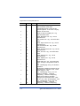
Chapter 6 - SV Command Language
Introduction........................................................................... 6-1
Data Match Commands – B.................................................. 6-1
Relationship Between ~BC and ~Br Commands ................. 6-5
Diagnostic Commands - D.................................................. 6-5
Hardware Configuration Commands - H............................ 6-6
Label Setup Commands - L .............................................. 6-11
Output Mode Selection Commands - O............................ 6-16
Output Port Setup Commands - P..................................... 6-17
System Control Commands - S ........................................ 6-23
ii
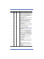
Output Interface Modes Descriptions ................................. 6-24
Mode 00 (~LV00)......................................................... 6-24
Mode 01 (~LV01)......................................................... 6-25
Mode 02 (~LV02)......................................................... 6-27
Mode 03 (~LV03)......................................................... 6-30
Mode 12 (~LV12)......................................................... 6-30
Mode 16 (~LV16)......................................................... 6-33
Mode 17 (~LV17)......................................................... 6-36
Mode 18 (~LV18)......................................................... 6-39
Mode 19 (~LV19)......................................................... 6-43
Chapter 7 - ANSI Parameter Grade Thresholds
Chapter 8 - Product Specifications
Scanning Performance–SV Series Model ...................... 8-2
Scanner Options ............................................................. 8-2
Sync ................................................................................ 8-2
Outputs ........................................................................... 8-2
Symbologies ................................................................... 8-3
Operation Modes................................................................... 8-3
Sync Mode – Moving Bar Codes ................................... 8-3
Sync Mode – Stationary Bar Codes ............................... 8-3
No Sync – Free Scan Operation ..................................... 8-4
Parameters Analyzed ............................................................ 8-4
Chapter 9 - Maintenance/Customer Support
Maintenance.......................................................................... 9-1
Cleaning.......................................................................... 9-1
Product Service and Repair................................................... 9-1
Online Product Service and Repair Assistance .............. 9-2
Technical Assistance............................................................. 9-2
Online Technical Assistance .......................................... 9-2
Limited Warranty.................................................................. 9-3
iii
iv
1
Quick Check SV Series
Introduction
The Hand Held Products SV Series of Scanner/Verifiers is a universal system
component that analyzes linear bar code print quality, checks encoded data, and
detects system failures. In its basic mode of operation, an SV unit acts similar to
a normal fixed position scanner by automatically decoding bar codes as they
pass through its laser beam. Additional capabilities, such as performing bar
code verification and operating in synchronous modes make the SV Series
unique.
The SV Series combines state-of-the-art digital signal processor (DSP)
technology, a proprietary high-speed moving beam laser scanner with unique
analog output capability, and flexible I/O and communications capability. This
powerful architecture makes an SV unit an economical Quality Assurance tool
for practically any bar code print, application, or conveyance system.
The SV Series performs practically every accepted method of bar code
verification – ANSI method, traditional method, encoded data format checks, and
laser scanning type analyses. These wide-ranging analysis parameters can be
used to measure bar code quality and detect failure mechanisms for any print
technology.
Bar code quality and encoded data information can be reported through the
serial communications port for each code analyzed, so accountability for all
printed bar codes is possible.
An SV Unit’s I/O consists of five programmable output ports, two programmable
display LED’s, and a sync input (with two interface circuit choices). This allows
the unit to be used as a local controller for pausing printers, activating lights,
gating conveyors, etc.
The SV Series is available in different models. All models operate identically, but
the scanner parameters, such as scans per second and focus distance, are
different.
Quick Check® SV Series User’s Guide
1-1
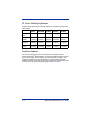
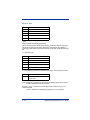
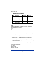
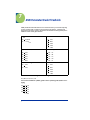
SV Series Model Specifications
Contact Hand Held Products Technical Support for information on custom and
other models.
SV100
SV100HD
SV100C
SV200-1
SV200-2
Analyses/
sec
100
100
100
200
200
Scan
Width
6”
(152mm)
4.5”
(114mm)
10.5”
(267mm)
2.5”
(63.5mm)
1.75”
(44mm)
Focus
Distance
8”
(203mm)
6”
(152mm)
15”
(381mm)
8”
(203mm)
6”
(152mm)
X dim
(min)
.0067”
(.17mm)
.005”
(.127mm)
.013”
(.33mm)
.0067”
(.17mm)
.005”
(.127mm)
ScanView Software
The recommended setup tool for the SV Series is Hand Held Products’
ScanView Windows®-based software. This program makes SV setup simple via
menus, plus it offers real time monitoring of bar codes being analyzed. This
program is available from Hand Held Products and authorized Hand Held
Products re-sellers. ScanView can be used to program the SV Series via serial
communication using SV download language. Refer to Chapter 6.
1-2
Quick Check® SV Series User’s Guide
2
Control Panel
The control panel displays the reset button, I/O connector, system LEDs, and the
serial port connector.
Reset Button
The Reset button is multifunctional. It may be used to turn off the laser beam,
perform calibration, and reset the ports.
Turn Off Laser Beam
The laser beam may be turned off (therefore turning off the SV unit’s operation)
by holding down the Reset button for a few seconds until the beam turns off.
Pressing the Reset button again will begin normal operation.
Note: There are some modes of operation when the laser beam is on only
during specific scanning times. (See the ~SA command (page 6-23) in
Chapter 6, SV Command Language .) Using the Reset Button for turning
off the system is not recommended in these modes.
Perform Calibration
The reset button is used in the calibration procedures. See "Calibration" on
page 5-4 for details.
Reset Ports
Pressing the Reset button will reset ports to their inactive states. This is useful
in systems where the SV unit is holding a printer in PAUSE mode and the user
desires to clear the pause condition. See "Output Ports" on page 2-4 for details.
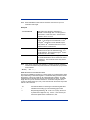
I/O Connector
The I/O connector is used for all power and field interconnections. The
connector is a DB 15 male. Pin-outs are shown below:
1 Isolated synchronization input (+)
2 Isolated synchronization input (-)
3 GND
4 Switch synchronization input
5 Output 1
6 Output 2
7 Output 3
8 Output 4
Quick Check® SV Series User’s Guide
2-1
9 10 11 12 13 14 15 -
Reserved
Reserved
GND
+5 VDC power in
Power GND
GND
Output 5
+ 5 VDC Power Input
The SV Series requires + 5 Volts DC, +/- 0.25 Volt. Maximum current
consumption is 1 amp. The voltage input must be connected to pin 12 and the
ground input should be connected to pin 13 on the I/O connector.
The alternate ground pins (3, 11, and 14) may be used for power ground or for
connecting the ground(s) of an external device(s) (such as presence sensors)
that may be powered from a different source than the verifier power input.
Sync Inputs
Utilizing a sync signal is recommended for all applications using hardware (as
opposed to communication) interfaces. (See "SV Command Language" on
page 6-1.) A sync signal is used to synchronize the SV Series to an object, label,
etc. that contains the bar code(s) being analyzed as it passes through the laser
beam. The SV Series should be programmed for the number of bar codes
expected per sync interval. This ensures a robust system that can report all
undetectable bar codes due to printer failure, missing labels, etc., along with
quality and data information on bar codes that are fully or partially decoded.
Two hardware sync inputs are available. Pin 4 is designed to be used with TTL
or open collector inputs. Pins 1 and 2 form a ground isolated input designed to
be used with systems that need separate grounds than the verifier and/or output
a higher voltage level than TTL.
Sync inputs are also available via serial communications.
Hardware sync operation is very flexible due to programmable options. Two
sync modes, edge and envelope, are available. Signal input polarity is also user
programmable.
Please see "SV Command Language" on page 6-1 for more information on the
use of these sync modes.
2-2
Quick Check® SV Series User’s Guide
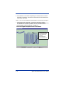
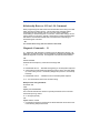
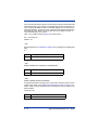
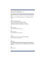
Edge Sync Mode
This mode senses a signal transition level of a sync signal as shown below.
Sync sensed here
The illustration above shows the sync operation of an SV unit programmed to
sense the rising edge of a sync signal in edge mode. Each time a rising edge is
sensed, the SV unit does the following:
1. It verifies that at least the number of bar codes expected (programmed)
since receiving the last sync input have been fully decoded. If not, a No
Read condition is internally set for possible reporting through communication
or output activation.
2. It begins a new interval, counting the bar codes analyzed until the next sync
input is received.
3. A serial communication report is transmitted and an output port is updated
per its programmed function each time a bar code is analyzed.
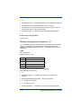
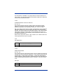
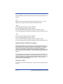
Envelope Sync Mode
This mode senses two transitions (leading and trailing) of the sync signal to
determine when to begin and end the period for determining missing bar codes:
Sync period starts here
Sync period ends here
The illustration above shows the sync operation of an SV unit programmed to
sense the rising voltage edge as the start of a sync period. The SV unit operates
in this mode as follows:
1. Upon receipt of the starting edge of a sync signal, the unit begins counting
the bar codes being scanned and analyzed.
2. A serial communication report is transmitted, and an output port is updated
per its programmed function each time a bar code is analyzed.
Quick Check® SV Series User’s Guide
2-3
3. Counting ceases upon receipt of the trailing edge of a sync signal. The SV
Series determines that at least the number of bar codes expected
(programmed) during the sync period have been fully decoded. If not, an
internal No Read condition is set for possible reporting through
communication or output activation.
4. The SV unit then waits for the next leading edge of a sync signal to begin
counting codes being scanned and analyzed.
Note: For best performance in either sync mode, mount the SV unit in a location
where a bar code is not in the laser beam when an active edge signal is
received.
Communication Sync Commands
Sync operation can be accomplished through serial communications. Please
see these commands in the SV Command Language Section – System Control
Commands (Chapter 6).
Output Ports
Five programmable output ports are available on I/O connector pins 5, 6, 7, 8,
and 15. Each port can be programmed to activate on practically any combination
of data and analysis parameters (including “good codes”) analyzed by the SV
Series. Port activation logic and parameters are programmed via the output
interface modes and associated commands. See the "Output Mode Selection
Commands - O" on page 6-16 for details.
Each port’s output is an open drain FET (field effect transistor). Therefore, the
port can either be “ON” (sinking current) or “OFF” (no current/open circuit). The
active polarity determines whether the port is “ON” or “OFF” while active. This
type of output circuit is used because it is flexible for field connections.
System Displays
Five LEDs are included on the SV Series back panel.
Power/Sync LED
This LED is illuminated green whenever power is applied to the SV Series. Upon
receipt of any sync input (hardware or serial communications), the LED blinks
yellow for approximately 100 milliseconds.
Calibration LED
This yellow LED indicates calibration status. Please refer to "Calibration" on
page 5-4 for details.
2-4
Quick Check® SV Series User’s Guide
Read LED
This green LED is illuminated whenever a bar code is being fully decoded.
Indicator LEDs 1 and 2
The two green indicator LEDs are user programmable exactly like the five output
ports. Their functions are intended for use as indicators for specific analysis
results.
A common example is programming LED 1 to illuminate in latch mode whenever
a symbol quality error is detected, while programming LED 2 to illuminate in latch
mode whenever a No Read error is detected.
Quick Check® SV Series User’s Guide
2-5
2-6
Quick Check® SV Series User’s Guide
3
Serial Port Connector
The serial port connector is used to interface the SV Series with devices
incorporating RS-232C signal levels. The connector is a DB 9 male.
The serial port can be used for reporting bar code analysis results to a host and
receiving SV Command Language instruction from a host.
Serial Port Specifications
•
•
•
•
Baud rate: programmable between 9600 and 115200 baud
Protocol: Echo back
Data: 8 bit, no parity, 2 stop bits
RS-232C compatible
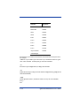
Serial Port Pin-out
Pin
Function
2
Receive Data (RXD)
3
Transmit Data (TXD)
4
Data Terminal Ready (DTR)
5
Ground
7
Request to Send (RTS)
8
Clear to Send (CTS)
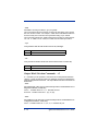
Serial Port Transmission Format
The following data transmission format is standard in the SV Series. This is the
format used by ScanView software for setup and monitoring of SV Series data.
All parameters analyzed for each bar code scanned are transmitted in the
following order:
YabbccddeeffgghhiijjkklmmnoopqqrsstttuuvwwwxxxxxxxxyyMNzzzzAAAABBB
CCCDDDEEFFGHHIIJJOKLL[bar code data chars]Z
Characters designated ‘a’ through ‘O’ represent values for Parameters analyzed,
which are described below. For more parameter details, see "Parameters
Analyzed" on page 8-4.
Quick Check® SV Series User’s Guide
3-1
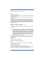
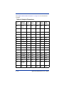
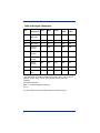
Legal values for each parameter are:
Pos
Chars
Y
1
1
a
2
1
b
3
2
c
5
2
d
7
2
e
9
2
f
11
2
g
13
2
h
15
2
i
17
2
j
19
2
k
21
2
l
23
1
m
24
2
n
26
1
o
27
2
p
29
1
3-2
Parameters
CR (carriage return) character indicates
start of transmit: ctrl-M; 0x0D
P=PASS Ref Decode, F=FAIL per Ref
Decode algorithm. P and F are a majority
decision over all scans.
00-9A (0-100); Decodability calc. avg.
over all decoded scans
00-9A; Modulation calc. avg. over all
decoded scans
0-9A; Defects calc. avg. over all decoded
scans
00-9A; Edge Contrast calc. avg. over all
decoded scans
0-9A; Rmin/Rmax calc. avg. over all
decoded scans
00-9A; SymbolContrast calc. avg. over all
decoded scans
00-9A; PCS calc. avg. over all decoded
scans
00-9A; R(white) calc. avg. over all
decoded scans
00-9A; R(black) calc. avg. over all
decoded scans
00-99; Ratio calc. avg. over all decoded
scans. Example: 29 represents a ratio of
2.9
+ or - indicating sign of avg. bar deviation
calculation.
Bar deviation calculation averaged over all
decoded scans. Units are % of X. Value:
00-9A (signify 0 – 100)
+ or - indicating sign of avg. min. bar
deviation calculation. + indicates
overprinting, - indicates underprinting.
Minimum bar deviation calculation
averaged over all decoded scans. Units
are in % of X. Value: 00-9A (signify 0 –100)
+ or - indicating sign of avg. max. bar
deviation calculation. + indicates
overprinting, - indicates underprinting.
Quick Check® SV Series User’s Guide
Pos
Chars
q
30
2
r
32
1
s
33
2
t
35
3
u
38
2
v
40
1
w
41
3
x
44
8
y*
52
2
M*
54
1
N
55
1
z
56
4
A
60
4
B
64
3
C
67
3
D
70
3
E
73
2
F
75
2
Parameters
Maximum bar deviation calculation
averaged over all decoded scans. Units
are in % of X. Value: 00-9A (signify 0 – 100)
One character: Pass(1) or Fail(0). Quiet
Zone. This is a programmable decision
over all decoded scans.
00-9A; Percent decode calc. avg. over all
decoded scans
Absolute X dimension in 0.1 mil (.0001
inch) resolution. Example: a value of 120
represents a 12 mil X dimension.
Overall ANSI method symbol grade
(numeric) Ave over all decoded scans.
Example: 26 = 2.6
Bar code decoding direction: Forwards(0)
or Backwards(1)
000-999; Calculated symbology mod check
value, Code 93 mod check C
8 hex digits; Self check value.
Two digit number identifies the symbology.
See Symbology Identifier Table on page 34 for details.
Digit: 0 = no error, 3 = symbology mod
check error, 4 = subsymbology mod check
error, 1, 2, 6 , or 7 = partial decode error
Digit; 0 = no error, 4 = data match field
length error, 5 = data match and Decrement
error, 6 = data match and increment error,
7 = decrement error, 8 =increment error, 9
= data match error
Four digit number indicates bar code
horizontal position.
Four digit number indicates bar code
vertical position.
Three digit number shows good scans-oncode. (00-9A)
Three digit number shows total scans-oncode.
000-999; Good Quiet Zones (scans)
Two digit number shows Lead QZ. Units:
.1X (00-9A)
Two digit number shows Trail QZ. Units:
.1X (00-9A)
Quick Check® SV Series User’s Guide
3-3
Pos
Chars
G
H
77
78
1
2
I
80
2
J
82
2
O
84
1
K
85
1
L
86
2
[chars]
88
...
Z
last
1
Parameters
One digit number: ‘0’ (off), ‘1’ (on). Sync
state.
Two: Units of X dimension times 10.
Two digits; Percent of good global
thresholds. (00-9A)
Two digits; Calculated application
checksum value or Code 93 mod check K
One digit; indicates the subsymbology
enabled in the y field of ~LFxy command for
this symbol. A value of 0 indicates no
subsymbology check is enabled.
One digits; Dummy value for expansion
Two digits; Dummy value for expansion
Bar code data characters (variable length).
LF(line feed) character indicates end of
transmit; ctrl-J; 0x0A.
y* - The symbology identifiers use groups of numbers to identify each
symbology. The range of possible values could potentially span 100 for each
symbology category. The Symbology Identifier Table lists each identifier group
with the corresponding symbology.
* A no read condition is indicated by all four bytes yy, M and N set to 0 in a
transmission. All other data is therefore not valid.
See the ~OS# command (page 6-17) for other transmission data formats.
Symbology Identifier Table
Identifiers
Symbology Category
02
I 2 of 5
03
Code 128
04
Code 93
05
Code 3 of 9
06
Codabar
11
UPC-A
15
UPC-A w/add-on (2)
19
UPC-A w/add-on (5)
12
EAN-13
16
EAN-13 w/add-on (2)
20
EAN-13 w/add-on (5)
3-4
Quick Check® SV Series User’s Guide
Identifiers
Symbology Category
13
EAN-8
17
EAN-8 w/add-on (2)
21
EAN-8 w/add-on (5)
14
UPC-E
18
UPC-E w/add-on (2)
22
UPC-E w/add-on (5)
Quick Check® SV Series User’s Guide
3-5
3-6
Quick Check® SV Series User’s Guide
4
ScanView Installation and Setup
Introduction
ScanView is designed to be a tool used for system setup and real-time bar code
monitoring of a Hand Held Products SV type scanner/verifier. It is a Windows 95/
98/NT/2000 application with facilities for sending commands to the SV scanner/
verifier and receiving the responses. The program can view bar code analysis
results and monitor bar code printing/monitoring sessions. In addition, it can
gather and display an ANSI method scan reflectance profile for a particular
symbol placed in the SV unit’s laser beam scan path. ScanView also streams the
analysis results received from the SV scanner/verifier to data files on hard disk
that can be reviewed by ScanView at a later time.
Note: This chapter refers to ScanView versions 2.08 and higher.
Note: If you are not using ScanView, skip this section and go to Chapter 5.
System Requirements
The following hardware and software is required to use ScanView:
1. A computer running either Windows 95, 98, 2000 or NT.
2. At least one available RS-232 serial port.
3. At least 32 MB RAM.
4. A hard disk with at least 15 MB of free space.
5. A color printer is recommended for users who wish to print analysis results.
ScanView Software Installation
There are two basic steps for installing ScanView. The program must be installed
and a communication port must be set up.
Note: Before installing a new version of ScanView make sure to uninstall
previously installed versions. To do this, select the Windows ‘Start’
button; the ‘Settings’ menu item; the ‘Control Panel’ to display the Control
Panel Window. Double-click on the ’Add/Remove Programs’ icon. The
‘Add/Remove Programs Properties dialog box appears. Click on the
‘Install/Uninstall’ tab. Scroll the list box to locate the ‘ScanView by Hand
Held Products’ item. Select that item and select the ‘Add/Remove’ button
Quick Check® SV Series User’s Guide
4-1
and follow the displayed instructions. If the previous version of
ScanView was 2.07 or earlier, delete the folder that contains the
remaining ScanView files: ‘c:/Program Files/Hand Held Products/
ScanView by Hand Held Products.’
Note: If you are using a CD-ROM, insert the CD and the system walks you
through the set up. If you are using 3.5 diskettes, follow the steps below.
Follow these steps to install ScanView:
1. Insert ScanView Installation Diskette #1 into a floppy disk drive; e.g., drive A.
2. Select the Windows 'Start' button.
3. Select 'Run...' menu item
4. Type A:\setup.exe.
5. Select ‘OK’ and follow the displayed installation instructions.
At the end of the installation procedure click the ‘Finish’ button to close the
ScanView Installation program. The ScanView Group Window remains, and it
contains the ScanView application icon. The icon label is ‘ScanView.exe’. To
place a shortcut to ScanView on the Windows Desktop, hold down the right
mouse button while dragging the ScanView icon to an open space on the
desktop; then release the right mouse button. A menu will appear. Click on the
‘Create Shortcut(s) Here’ menu item.
Launch the ScanView application by double-clicking on the ScanView icon.
(ScanView can also be launched by clicking the Windows ‘Start’ button, then by
clicking the ‘Programs’ menu item, and finally, by clicking the ScanView submenu item.)
The first time ScanView is launched, a dialog box is displayed that shows all of
the communications ports on the PC in a drop-down list. Select the
communications port that is connected to the SV scanner/verifier.
The initial screen displayed after successful installation is the Bar Code Analysis
Screen. This is shown in page 4-9 and described in the Analysis Screens
section.
PC Communication Port Setup
Connect the null-modem cable between the SV unit and the PC serial com port.
The PC communication port settings must match the ScanView communication
parameter settings. To match the communications port baud rate to the verifier
baud rate, click the Setup item on the application Menu Bar (See "Bar Code
Analysis Screen" on page 4-9). Then click the ‘Match Verifier Baud rate” menu
item. ScanView will detect the verifier’s baud rate, and set the port to the
detected value.
4-2
Quick Check® SV Series User’s Guide
Software Operation Warnings
Do not run other Windows applications run concurrently with ScanView.
ScanView operation depends on communication and timing issues that can be
disrupted when ScanView shares Windows resources with other applications.
The resource sharing problem can include conflicts with Windows screensavers.
ScanView blocks screensaver operation.
This version of ScanView limits the number of processed bar codes to 30,700 per
session. To use ScanView for monitoring larger amounts of bar codes, divide the
job into multiple sessions, each less than 30,700 bar codes.
Title Bar – Screen Display
See "Bar Code Analysis Screen" on page 4-9. The area marked B is the title bar.
The application Title Bar is located at the top of the application window. It shows
the application’s name and the name of the data file that receives the analysis
results generated by the verifier. The title changes to identify the current display
mode.
The Title Bar also includes the standard Windows Minimize, Maximize and
Application Termination buttons.
Menu Bar – Screen Display
See "Bar Code Analysis Screen" on page 4-9. The area marked C is the Menu
Bar. The Menu Bar is located just below the Title Bar. It lists five menu
categories: File, Setup, Advanced, Support and About.
File Menu
This menu controls data file handling functions, printing and application
termination. The format is typical of any Windows type file menu. The files
contain the raw data collected from the SV unit. ScanView can re-open these
files to re-display the data at a later time. Note: The Print function prints the
current ScanView display on the printer.
Setup Menu
This menu is used to configure the ScanView analysis displays and program the
most common SV scanning and communication parameters.
Select Graphs
This item allows the user to select which bar code analysis parameter graphs are
displayed on the Bar Code Analysis Screen (see "Bar Code Analysis Screen" on
page 4-9.)
Quick Check® SV Series User’s Guide
4-3
Select Symbologies
This item allows the user to program the SV unit to enable/disable individual
symbology decoders. This is useful for either more secure decoding or
sometimes faster throughput if a single symbology type is always being
analyzed.
Select Com Port
This item allows the user to select a com port in the host PC.
Change Verifier Baud Rate
This item allows the user to program the SV scanner/verifier baud rate.
Match Verifier Baud Rate
This item detects the baud rate of an SV scanner/verifier; then it changes the
ScanView baud rate setting to the detected value. This is useful when using
ScanView as a diagnostic tool in a system that is using the SV communication
interface. ScanView can easily be inserted in the system without re-programming
the SV serial port, therefore when re-connecting the SV unit back to the host, all
communication parameters remain compatible with the host.
Static Codes Mode
This item allows the user to set the SV unit in static codes mode.
Moving Codes Mode
This item allows the user to set the SV unit in moving codes mode.
Data Match
This item opens a dialog box that lets the user configure the Data Match feature.
Minimum Codes Per Sync
This item allows the user to program the minimum number of bar codes expected
in a sync interval. This parameter is important for detecting No Read conditions
when a sync input is being used.
Ladder Mode and Picket Fence Mode
These items allow the user to program the SV unit to scan bar codes traveling in
either “picket fence” or “ladder” direction. “Picket fence” orientation is defined as
the bar code traveling through the laser beam in the direction of the height of its
bars. “Ladder” orientation is defined as the bar code traveling through the laser
beam in the direction of the beam path.
4-4
Quick Check® SV Series User’s Guide
Note: In cases where the SV is scanning stationary bar codes, the “picket fence”
direction must be used.
Advanced Menu
This menu is an extension of the Setup Menu, providing less commonly used, but
useful SV system features.
Toggle Display Updating
This item enables/disables display updates in real time. Disallowing updates is
useful to allow ScanView to keep up with a high throughput application.
Toggle Additional Results
This item enables/disables additional analysis parameters to be displayed on the
Bottom Panel of the Bar Code Analysis Screen. The additional parameters are
intended for debug use only while working with Hand Held Products’ Technical
Support.
Download New Firmware
This item is used for updating the firmware revision level in an SV scanner/
verifier.
Port Configuration
This item lets the user configure the SV unit output port activation threshold
settings.
Initialize the Com Port
In the unlikely event that some failure causes the Com Port to lock up, this
feature can be used to unlock the port.
Support Menu
This menu provides special diagnostic displays that are intended to be used only
while working with Hand Held Products’ Application Support.
About (Menu Item)
This item lists information about the origin of ScanView, the version number of
this copy (it also queries the SV unit for its firmware version number) and it shows
the copyright warning.
Quick Check® SV Series User’s Guide
4-5
Speed Button Bar – Screen Display
See "Bar Code Analysis Screen" on page 4-9. The buttons on this bar give quick
access to various application modes and features.
All Data Points, Last 64 Data Points
,
Toggles the “all data points” mode and the ‘last 64 data points”
mode. In the ‘last 64 data points” mode, the Graph Display Area (see "Bar Code
Analysis Screen" on page 4-9) is updated immediately as the SV scanner/verifier
processes each bar code. In the “all data points” mode, bar code processing can
continue, but the ScanView display is not updated. The Grade Bar (Color Bar)
is dimmed when in All Data Points mode.
Zoom In
Toggles the Zoom-In mode. First, it switches from Last 64 Data Points
mode (see All Data Points, Last 64 Data Points Section above), to All Data Points
mode (see All Data Points, Last 64 Data Points Section above). To zoom-in, hold
down the left mouse button and drag the mouse-pointer to a desired data point
in the Graph Display Area; Hold down the Ctrl-key when the left mouse button is
released (then release the Ctrl-key.) The plots are stretched to show only half of
the data on each side of the mouse pointer. To zoom further into the data, repeat
this process.
Erase Current Session Data
Erases all of the data in the current session. Also, the data in the
corresponding hard disk files is deleted.
Reflectance Profile
Scan and Display a new Reflectance Profile. (See "Reflectance Profile
Screen" on page 4-12.) The shortcut key for this function is F3.
4-6
Quick Check® SV Series User’s Guide
Transmit SV Commands
This button invokes a special screen where up to fourteen individual
commands may be composed and transmitted in any order. Proper use requires
knowledge of the SV download language. See the Chapter 6, SV Download
Language for details. This function is intended for advanced setup involving
special functions not normally accessed by ScanView. These can include special
transmission formats, special commands in a custom SV firmware version or
diagnostic functions used by Hand Held Products’ Application Support and
Service personnel. The shortcut key for this function is F4.
Report an Analysis
Reports a new analysis of any bar code(s) currently in the SV
unit’s beam path. This is most useful in setup where scan distance and
orientation is being finalized. It is also useful when using the SV unit as a
standalone verifier scanning codes being manually placed in the beam by the
user. The shortcut key for this function is the Spacebar.
Modes Of Operation
ScanView operates in two basic modes: Session and Reflectance Profile.
Session Mode
This mode scans, analyzes and provides reports on individual bar codes.
Reporting is accomplished via the Bar Code Analysis Screen (see "Bar Code
Analysis Screen" on page 4-9). The parameters analyzed and many of the
parameters displayed are user programmable
Session Mode is entered by default when the program is initially started. It can
also be entered from the Reflectance Profile Mode by clicking the Return to
Session Mode Speed button (see "Reflectance Profile Screen" on page 4-12.)
The Bar Code Analysis Screen (see "Bar Code Analysis Screen" on page 4-9) is
displayed and analysis from bar codes passing through the SV unit’s beam will
be displayed. In cases where a bar code is statically held in the beam analysis of
the code can be accessed by clicking the Report an Analysis Speed button.
Session Mode Notes
ScanView updates the bar code analysis graphs each time a bar code is
processed by the verifier; but there is a limit to the graph update rate that
ScanView can sustain. Factors that determine the processing load include the
bar code analysis rate (bar codes per second) and the number of displayed
analysis parameter graphs (selected by the user). The Windows
communications facility has a data buffer that allows the graph processing to
‘catch up’ between bursts of transmitted data. If the incoming data volume
Quick Check® SV Series User’s Guide
4-7
exceeds the application’s processing limit it will lag farther and farther behind
until the buffer overflows and the communications port ceases to operate. If this
condition occurs, port operation can be restored by clicking the Initialize Com
Port item in the Support Menu list. When using ScanView to monitor a printing
session, the user can test for processing lag during short sample runs by
intermittently blocking the beam path and noting the resulting analysis graph
update lag. If the apparent lag time is longer when the time between blocking the
beam is longer, then an adjustment is required; either reduce the speed the bar
codes are traveling through the laser beam or change to a ScanView display
mode that requires less graphic processing. (e.g., see "Toggle Display
Updating" on page 4-5 .)
ScanView streams the verifier analysis results directly to data files on hard disk
as the data are received from the verifier. There are two data files: one, contains
the verifier analysis results; the other file contains the date and time when each
bar code was processed (supplied by the PC clock). The two default files are
deleted and a new pair of default files are created each time the ScanView
application is launched. Therefore, the user must rename the files to preserve
session analysis results. To do this, use the ‘Save As’ item in the File Menu.
Enter a filename without a trailing file-type identifier. ScanView uses that name
to create two files: one, for the session analysis results data (.ses); and the other
for the date/time data (.tim).
When ScanView is launched it exhibits the same configuration it had when it was
last shut down. The configuration parameters that are maintained between
application launches include window position, shape and the user selected
display mode options. The configuration saving capability extends to selected
application’s dialog boxes that can be repositioned and reshaped by the user.
Reflectance Profile Mode
This mode gathers and displays a scan reflectance profile for the entire scan
path. The profile is displayed with the Reflectance Profile Screen (see
"Reflectance Profile Screen" on page 4-12.) Reflectance Profile Mode is
enabled by clicking the Reflectance Profile Speed button or pressing F3.
Analysis Screens
There are two analysis screens used for setup and monitoring an SV type
scanner/verifier. These are the Bar Code Analysis Screen and the Reflectance
Profile Screen.
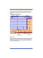
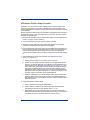
Bar Code Analysis Screen
This screen provides all analysis results for a particular bar code. It also shows
many bar code analysis results over time. An example is shown below. Each
individual parameter analysis result for one bar code is indicated by a dot on a
parameter graph in the Graph Display Area and can be easily accessed via the
mouse.
4-8
Quick Check® SV Series User’s Guide
Various points on the screen are marked with numbered and lettered references.
Lettered references apply to ScanView screens in general. The numbered
references apply to this screen in particular. Descriptions for each point are
included.
Bar Code Analysis Screen
Speed Button
Title Bar
Bottom Panel
Bar Code
Analysis Results
Menu Bar
Graph Display
Right Panel
Bottom Panel
Results are presented for one bar code (the default shows the results for the last
processed bar code indicated by the column of dots at the far right of the Graph
Display Area). Results for other bar codes may be reviewed by dragging the
mouse pointer (while holding down the left mouse button) to the data point of
interest in the Graph Display Area.
Quick Check® SV Series User’s Guide
4-9
Bar Code Analysis Results for a Previous Bar Code
This is an example of reviewing a bar code other than the last one processed as
described in the Bottom Panel explanation above. A vertical line appears while
dragging the mouse with the left mouse button held down. Analysis results are
shown for the column of dots (the bar code) nearest the vertical line. For
example, the Bar Code Analysis Screen above exhibits the analysis results for
31st bar code in the session.
Graph Display Area
This area of the display shows bar code analysis results for each graph type
selected by the user. Analysis results are indicated by a dot’s vertical position
within a plot and by the dot’s color. The displayed parameters are programmed
via the Setup Menu in the Menu Bar.
Note: In All Data Points mode (see the Speed Button Bar - Screen Display, All
Data Points, Last 64 Data Points (page 4-6)), if enough bar codes are
analyzed, the displayed data points begin to merge together into a
continuous line. In this case the Zoom-in Speed button can be used to
see individual data points. Refer to "Bar Code Analysis Screen" on
page 4-8 for information on how to select the analysis results display for
any processed bar code.
Right Panel
This area displays additional analysis results of the code described in the Bottom
Panel section. Unlike the Bottom Panel, the parameters displayed in this section
are user programmable via the Setup Menu in the Menu Bar. Click on the Select
Graphs menu item.
4 - 10
Quick Check® SV Series User’s Guide
Color Coding
Color Coding is an important feature of the ScanView presentation scheme. If
you look at your monitor, you can see that the display contains different colors.
Medium blue, light blue, yellow, magenta and red indicate ANSI method bar code
parameter grades A(4), B(3), C(2), D(1) and F(0), respectively. Each dot is color
coded to show the grade for that particular parameter for that particular bar code.
Color/Grade Reference Chart
Dot indicates the ANSI grade
value of a bar code.
Color/Grade Bar
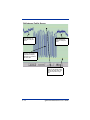
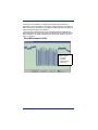
Reflectance Profile Screen
This screen displays a reflectance profile for SV unit’s entire scan path. An
example is shown below.
Quick Check® SV Series User’s Guide
4 - 11
Reflectance Profile Screen
This high reflectance
spans includes one
of the bar code quiet
zones.
This high reflectance
spans includes one
of the bar code quiet
zones.
In this case, the bar code
segment of the profile is
centered in the display;
therefore it is centered in
the beam path.
The amplitude of the bar code
signal is in the desired location
between the yellow lines (10%
and 90% of dynamic range)
path.
4 - 12
Quick Check® SV Series User’s Guide
SVScanner/Verifier Setup Procedure
Installation of an SV scanner/verifier requires proper mounting position and
output port configuration to ensure the reliable and accurate operation. This
section describes the procedures for using ScanView to ensure proper SV setup
and installation.
Each SV unit has a label showing the specified mounting distance and angle for
its particular scanner. Follow the steps below to ensure the SV unit is properly
mounted and programmed.
1. Mount the SV units at the proper distance and angle. Use "Good Reflectance
Profile" on page 4-15 as a reference.
2. Connect the power and communication cables to SV unit.
3. Set the SV unit for picket fence bar code travel direction by clicking the
Picket Fence Mode item in the ScanView Setup Menu.
4. Place a sample bar code in the center of the intended laser beam path. For
best results, this sample should match the type of bar code(s) and material
that is to be analyzed in the final application. Knowing the X dimension
(narrow element width of the bar code(s) is a big plus as will be seen in Step
5.
5. Take a Reflectance Profile with ScanView (see "Reflectance Profile
Screen" on page 4-12).
a. Ensure the bar code(s) is in the center of the scan path.
b. Ensure the scan profile contains no distortion from light reflecting from
objects in or near the light path. (An example of a good reflectance profile is provided in the "Reflectance Profile Screen" on page 4-12.). One
major aspect in a good profile is the low reflectance points (the bars) in
the symbol are uniform all the way across the code. Optimum signal
amplitude should be adjusted so the bar code element reflectances are
between the 90% and 10% marks shown in yellow on the screen. Scanner angle has the most effect on the signal amplitude.
c. Continue adjusting the SV unit’s placement until a good, centered scan
profile is obtained. The scan angle may have to be altered slightly or a
light shield may have to be installed in extreme cases to achieve a good
reflectance profile.
6. *Place ScanView in Session Mode.
a. Click on the Report an Analysis Speed button.
b. Ensure that X in the bottom panel of the Bar Code Analysis Screen
matches the X dimension of the symbol within +/- .1 mil.
c. Adjust distance of the SV100 from the bar code until the X dimension
matches the desired value. (If X is analyzed as too large, move the scanner farther away; if X is too small, move the scanner closer.)
Quick Check® SV Series User’s Guide
4 - 13
7. Repeat steps 4 and 5 until no more mounting adjustments are required.
8. Remove the symbol from the laser beam path.
9. Program the SV unit’s ports, sync mode, etc. (if required).
10. Calibrate the SV unit if any reflectance parameters (such as symbol
contrast) are programmed in this application to report to a host or activate
any ports. Each SV unit is supplied with a calibration symbol.
11. The SV scanner/verifier is now ready to operate for picket fence bar code
travel direction. If Ladder Mode is being used and the desired scanning
length for ladder bar code travel direction is programmed, place the unit in
ladder mode. The unit is now ready to operate.
Note: If ladder mode scanning length is to be programmed, continue with the
following steps.
12. Turn off partial decodes using the ~Lp0 command.
13. Display additional results in ScanView through the Advanced Menu.
14. **Place a sample of a bar code that is to be analyzed on the farthest
position towards the left end of the laser beam where the code is intended to
be scanned.
15. Analyze the code by clicking the ScanView Report an Analysis Speed
Button.
16. Confirm the code is being read and analysis results are proper. If not, move
the code to the right until acceptable analysis results are achieved.
17. Record the value of the “Hor Pos” value in the additional parameters for the
acceptable analysis. This value will consist of four digits. This value will be
used for the “Set Ladder Start Position” setting later in the procedure.
18. Move the code to the farthest position towards the right end of the laser
beam where the code is intended to be scanned.
19. Similar to steps 15, 16 and 17, obtain an acceptable analysis and record
the “Hor Pos” value for the acceptable analysis. This value will be used for
the “Set Ladder Stop Position” setting later in the procedure.
20. Place the unit in Ladder mode through the Setup Menu. Place the proper
values for the “Set Ladder Start Position” and “Set Ladder Stop Position”
boxes during menu process.
21. Enable partial decodes if desired for this application.
22. The unit is now ready to operate for ladder bar code direction.
4 - 14
Quick Check® SV Series User’s Guide
*This step is not mandatory, but highly recommended. Scanner focus is
dependent on the scan distance. Good focus maximizes the SV unit’s ability to
detect printer errors and failures. If this step is omitted, take extra precaution in
setting and measuring the scan distance.
**This procedure assumes the SV unit is mounted as shown below with the
protruding surface up and the user is looking at the beam from behind the SV100.
In this orientation, the beam is sweeping from left to right. Refer to "Scanner
Setup" on page 5-1.
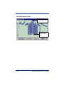
Good Reflectance Profile
Example of “good” scan
reflectance profile:
• Consistent
amplitude
• Amplitude within
yellow lines
Quick Check® SV Series User’s Guide
4 - 15
Bad Reflectance Profile
Bar code signal amplitude
out of range; above yellow
line and also off the graph.
Bar code low
reflectance points not in
straight, consistent
values.
4 - 16
Quick Check® SV Series User’s Guide
5
Scanner Setup
Scanner positioning and proper system setup are extremely important for proper
SV Series operation.
Positioning is important to provide accurate analyses. The scan distance must
be set accurately to achieve the proper beam focus to detect printer flaws and
failures, such as a worn ribbon (matrix printing), low toner (laser printing), voids
(flexo printing), burned pixels (thermal printing). The scan angle is important to
accurately measure bar code and substrate reflectance values.
Setup is important to ensure proper interface to print mechanisms and host
computers.
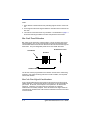
Scanner Positioning
Each SV Series has an attached label that indicates the type of scanner, focus
distance and recommended scan angle. Use the scan distance and scan angle
information in the following illustration to mount the scanner.
Scan Distance
Laser Beam
Scan Angle
Beam Intersects Bar Code Here
Quick Check® SV Series User’s Guide
5-1
Notes:
1. Scan distance is measured from the protruding edge of the face of the scanner.
2. Scan angle is measured in degrees relative to vertical from the surface of the
bar code.
3. The scanner can be mounted in any orientation. The illustration on page 5-1
shows the beam angle relative to the bar code placement in the beam.
Bar Code Travel Direction
Bar codes can be scanned in a static location, or more commonly with on-line
scanner/verifiers, they can be scanned while moving through the laser beam.
The illustration below shows the two directions a bar code can travel through the
laser beam. They are designated “picket fence” and “ladder” directions.
Picket Fence Travel
Laser Beam
Direction
Ladder Travel Direction
The SV unit must be programmed for the direction of travel of the codes being
analyzed. If the codes are being scanned in a static condition, use the picket
fence travel direction.
Bar Code Travel Speed Considerations
A bar code should be present in the beam for at least five scans for the most
reliable operation. The SV Series performs a minimum of 100 scans/analyses
per second. At that rate, each analysis is accomplished in 10 milliseconds
maximum. Therefore, a bar code must be in the beam for at least 50
milliseconds to be reliably analyzed. Some SV models have higher minimum
scans/analysis; therefore a bar code must be in the beam for less amount of time
for those models.
5-2
Quick Check® SV Series User’s Guide
Picket Fence Direction
In picket fence travel direction, a bar code is in the laser beam throughout the
height of the shortest bar in the code. An easy way to estimate the fastest speed
the code can travel through the beam is to divide the height of the shortest bar in
the code by the maximum time required for the SV unit to take five scans of the
code. For example: Calculate the maximum travel speed where the shortest bar
height in a code is .5 inches and the SV model being used performs a minimum
of 100 scans/analyses per second. Five scans requires 50 milliseconds (.05
seconds) to gather, so .5 inches (bar code height) divided by .05 seconds (time
needed to gather 5 scans) = 10 inches/second. Therefore, the maximum speed
the code can travel through the beam is 10 inches per second.
Vertical distance between bar codes is also a speed consideration in picket fence
direction. The SV Series must have five continuous scans where no bar code is
detected to reliably exit a bar code when operating in the standard operation
mode set by Command ~HO1. Assuming 100 scans per second minimum, this
means the vertical distance between the codes must take at least 50
milliseconds to pass through the laser beam. Calculate the maximum speed by
measuring the shortest vertical space between bar codes on a label (or between
labels.) Divide this distance by .050 (seconds). The result is the fastest speed
the codes can move through the beam. If the application travel speed cannot be
met due to a short vertical distance between codes, Command ~HO2 can be
used to cause the SV to exit on a change in data rather than detecting no bar
code.
Note: If using ~HO2, ensure the bar codes with short vertical gap are encoded
with different data and only one code across is being analyzed in each
scan.
Note: The slower of the two print speeds calculated above for bar height and
gap height is the maximum recommended speed for picket fence travel.
Picket Fence Bar Code Positioning Specifications:
• Four codes across maximum
• Horizontal gap between codes: .5 inch (13 mm) minimum
• Maximum number of codes per sync period: 99
Ladder Direction
In ladder direction, one bar code at a time is usually in the beam. The amount of
time the code is in the beam is a function of the total width of the code (including
quiet zone), the length of the beam area that is used for scanning and the speed
the code is travelling. The distance the bar code is in the beam is calculated by
subtracting the bar code width from the length of the beam programmed to scan
the bar code. (See "Setting Ladder Mode Scanning Length Using ScanView
Software" on page 5-4.) Divide this difference by the amount of time the SV
model requires to gather 5 scans to get the maximum speed. For example, a bar
Quick Check® SV Series User’s Guide
5-3
code with total width of 3 inches is to be analyzed in a beam length of 6 inches
and the SV model being used performs a minimum of 100 scans/analyses per
second. Maximum speed of travel is (6 –3)inches /.050 seconds = 60 inches per
second in ladder direction.
Setting Ladder Mode Scanning Length Using ScanView
Software
The distance and location in the laser beam where a bar code is scanned
sometimes must be tuned (programmed) for a particular ladder mode
application. In general, the wider the length, the faster the bar codes can travel.
In some cases, a narrower scan length is required to mask an adjacent code so
only one code at a time is scanned. Instructions for using ScanView software to
program the scanning length is provided in "SVScanner/Verifier Setup
Procedure" on page 4-13.
Calibration
Calibration is required if any reflectance calculation (e.g., symbol contrast, Rmin,
PCS) is used in the application. It is recommended to calibrate the unit in any
case during initial setup to ensure the scanning distance and orientation is within
device limits. A calibration symbol is supplied with each SV unit as a standard
component. Store this symbol in a clean location.
The SV Series can be calibrated using either of the two following procedures:
Procedure 1
1. Remove all bar codes from the laser beam path.
2. Place the supplied calibration symbol in the laser beam in the same position
(distance and angle) as the labels to be verified will be scanned.
3. Press and hold the RESET button on the SV unit until the Calibration LED
begins to flash.
4. Release the RESET button immediately after the Calibration LED begins
flashing.
If calibration is successful, the laser beam will go off and the Calibration LED will
go off.
5. Remove the calibration symbol from the beam path, and press the RESET
button until the beam turns on. The SV unit is now ready to operate.
If calibration is unsuccessful, the Calibration LED will be either on steadily or
flashing. In this case, repeat the calibration procedure.
Procedure 2
1. Place the supplied calibration symbol in the laser beam in the same position
(distance and angle) as the labels to be verified will be scanned.
5-4
Quick Check® SV Series User’s Guide
2. Send “~SC” into the SV unit serial port. This will cause the Calibration LED
to flash.
3. If calibration is successful, the laser beam will go off and the Calibration LED
will go off. Remove the calibration symbol from the beam path and then
Press the RESET button until the beam turns on. The SV unit is now ready
to operate.
4. If calibration is unsuccessful, the Calibration LED will be either on steadily or
flashing. In this case, repeat the calibration procedure.
Once calibration is successful, re-calibration is not required unless the unit has
been moved – either on its mounting stand or into a new location. It is advised
to keep the laser beam exit window clean. Dirt, dust, and fingerprints on the exit
window can affect calibration.
Adjusting Scanner Gain and Offset
Scanner gain and offset adjustment via commands is available in SV units that
have the “A” circled on the label that indicates focus distance. The adjustment
capability is useful for adapting the unit to various material types and scanning
angles during the setup procedure. Knowledge of Hand Held Products’
ScanView software is required for best understanding of the following
description.
When setting SV scanner gain and offset, use ScanView Reflectance Profile
Mode as the guide to viewing signal levels. The object is to have at least 6 lines
high of signal amplitude for the bar code(s) being verified. The bar code signal
vertical placement (offset) should be within the yellow lines to ensure the signal
is in the linear range. All other objects’ amplitudes and placements are not
important. A picture of a “good” signal level is shown on page 5-6.
To adjust gain and offset settings, first use the ScanView Transmit SV
Commands Screen to send a ~HT command to the SV unit. In the reply, look for
the line that reads [DACs] = nnn nnn nnn nnn where nnn = numeric values.
Example: a unit may read: [DACs] = 201 146 255 255. This indicates the current
settings.
1. The 201 indicates the value of the gain setting. The higher the value, the
higher the gain and therefore the higher the amplitude of the scan profile for
a symbol. Max value is about 225.
2. The 146 value indicates the offset setting. The higher the value, the lower
the symbol placement is offset on the graph.
3. The command ~Hd101nnn sets gain where nnn is the three digit value.
4. The command ~Hd201nnn sets offset where nnn is the three digit value.
5. Use these commands to set the desired signal amplitude ( ~Hd101nnn) and
locate the signal vertical placement between the yellow lines ( ~Hd201nnn.)
Quick Check® SV Series User’s Guide
5-5
6. A few iterations of commands will probably be needed, therefore it will be
necessary to access the Transmit SV Commands Screen and Reflectance
Profile Mode alternately.
Note: A short cut to the Reflectance Profile Mode is accessed by pressing F3.
7. Like most other SV commands – new scanner settings are enabled
immediately when received, but to be stored to non-volatile memory so they
are maintained on a power up condition, the ~Hx command must be
transmitted after the desired settings are achieved.
Desired Signal Amplitude and Placement
• Bar code signal amplitude
at least 6 lines high. (A
more preferred 7 lines
high is shown in this
example.)
• Bar code signal
placement within the
5-6
Quick Check® SV Series User’s Guide
6
SV Command Language
Introduction
All commands to the verifier begin with a tilde, ‘~’, followed by one or more
alphanumeric characters. The ‘~’ identifies the subsequent character string as a
verifier command. The string is parsed from left to right. The first character after
the ‘~’ identifies the command category. Each command requires at least one
additional character that identifies the particular command from that category.
Some commands require additional data, e.g., a data value, or an option ID
character, or a text string. These values are included at the end of the command
string. The command string format is shown below. As each character is
received by the SV unit, it echoes back the same character. Echo-back is used
to determine when the verifier has completed the command action. The verifier
is ready to receive the next command when the last character of the command
is transmitted (echoed-back) to the host.
~CPx…
~ - indicates the start of a command string.
C - a character that identifies the command Category
P - a character that specifies the Particular command in the category
x… - a number or text string (as necessary)
Data Match Commands – B
A ‘~’ followed by a ‘B’ specifies a command from the Data Match category. All
Data Match commands include a second alphabetic character that identifies the
particular diagnostic command. The Data Match Commands are listed below.
An important consideration when using data match type commands is the data
format. These commands incorporate a “scanner” philosophy rather than a
“verifier” philosophy. A scanner philosophy is to report the data encoded in a
symbol while a verifier philosophy is to report all symbol characters whether they
include data or not. Symbol characters typically include stop character, start
character, symbology mod check digit(s), internal control characters, etc.
depending on the symbology type.
The data fields described in the B commands below include data characters only,
therefore the ~B commands have a “scanner” philosophy. The one possible
exception is in UPC or EAN symbols the symbology mod 10 check digit is also
considered a data character.
Quick Check® SV Series User’s Guide
6-1
~BCa##bc{…bbb…}{…mmm…}{…bbb…}… {etc. up to 32 characters max.}
Check for specific data
This command sets (enables) or clears (disables) one of 10 available data match
arrays. All ten arrays may be active simultaneously. A data match error occurs
if at least one array is active and the data scanned does not match the data
programmed in the array. Each array can be up to 32 characters in length.
Multiple portions of each array can be masked and the mask character is defined
in the command. The data in the array must consist of printable ASCII characters
with ASCII values less than 128.
~BC
Data Match Command
a
1 digit. A number between 0 and 9. It identifies the data
match array being programmed or cleared.
##
Number of data characters in the Data Match array. The
value can be 01 through 32. A value of 00 clears (disables)
this array.
b
This character defines the fill character for masking purposes. This character cannot be a character to be matched
in the match field mmm.
c
This character defines the size of the data match field to be
fixed (“f”) or variable (“v”). If variable, the data in the field is
left justified in a 32 character possible field.
...bbb...
Fill characters prior to the Data Match text. These characters must match the character defined by b in the command.
...mmm...
Data Match Character Field. This can be from 1 to 32 characters. These define the exact characters that must be
matched.
...bbb...
Fill characters after to the Data Match text (if needed).
6-2
Quick Check® SV Series User’s Guide
Note: Other Data Match Fields and Fill characters can follow for up to 32
characters total length.
Examples
~BC005xfABCDE
Data match array #0 with 5 characters of
“ABCDE” of fixed length with ‘x’ as the ignore or
fill character. In this case, the ‘x’ must be in the
command, but is not used
~BC210xfxxxABCDExZ
Data match array #2 with 10 characters of fixed
length. ‘x’ as the ignore or fill character. The 4th
through 8th characters must be ABCDE respectively and the 10th character must be a Z in a 10
character field for a data match.
~BC004xvx111
Data match array #0 is defined as variable length,
therefore can be up to 32 characters long. ‘x’ is
the fill character. The second through 4th characters all must be 1 for a match.
~BC000bc
Disable Data match array #0. Any proper character as described above can be used for the b and
c characters. The remainder of the array data is
not required.
Note: In the above examples, the character ‘x’ (defined as the fill character)
cannot be included in the portion of the bar code data that is programmed
to be matched.
~ Brnbb{ .. + 0-9.. ! .... )
Define increment or decrement data check
One array is available for checking a numeric (base 10) or alphanumeric (base
36) incrementing or decrementing field. The data field being checked must be
fixed length. Portions of a field can be checked through masking. An initial
(starting) value for the field may also be programmed in the array. Total field
length can be up to 32 characters maximum. Characters analyzed can be
numeric or alphanumeric (0-9, A-Z). This command can be used in conjunction
with the ~BC command.
~B
Command initiation for checking an incrementing data field
r
Indicates incrementing (I) or decrementing (D) function
n
Required digit following ~Br. If set to a ‘0’ (zero), the check
is performed for digits 0-9 only. If set to 1, the check is performed for alphanumeric characters 0-9, A-Z.
Quick Check® SV Series User’s Guide
6-3
bb
Number of characters in array. A value of 00 clears (disables) this array.
...!!!
Mask characters for defining positions in the data field not
being checked.
...+++
Characters in the data field being checked. If + characters
are used, this marks the field and defines its size. Maximum
field lengths are 8 characters for numeric and 6 characters
for alphanumeric. If a proper numeric or alphanumeric value
is placed in the field, this additionally become the initial value
expected on the first data scanned after a power-up or reset.
Incrementing Examples
~BI010!!!!!!!+++
Increment is to be done in the last three characters of the 10 character array.
~BI010!!!!!!!234
Increment is to be done in the last three characters
of the 10 character array. Initial value scanned
must be 234.
~BI010!!!!!+++!!
Increment is to be done in location 6 through 8
characters of the 10 character array.
Decrementing Examples
~BD010!!!!!!!+++
Decrement is to be done in the last three
characters of the 10 character array.
~BD110!!!!!!!C34
Decrement is to be done in the last three
characters of the 10 character array. The initial
value scanned must be C34 (base 36
alphanumeric field).
~BD010!!!!!+++!!
Decrement is to be done in location 6 through 8
characters of the 10 character array.
~BI000 or ~BD000
Disable the Increment/Decrement array. The
remainder of the array data is not required.
6-4
Quick Check® SV Series User’s Guide
Relationship Between ~BC and ~Br Commands
When programming both data match and increment/decrement arrays, the data
match array(s) have higher priority. This is useful when analyzing a label
containing more than one bar code, and one of the codes contains an
incrementing or decrementing field. In this case, a data match array(s) can be
used to match (or in this case – logically “mask”) the bar code(s) containing static
data and the increment/decrement array can analyze the incrementing or
decrementing bar code data.
~ BT
Lists all Data Match strings and Increment/Decrement fields.
Diagnostic Commands - D
A ‘~’ followed by a ‘D’ specifies a command from the Diagnostic category. All
Diagnostic commands include a second alphabetic character that identifies the
particular diagnostic command. The Diagnostic Commands are listed below.
~DF
Get the Scan Rate
Possible returned frequency values are 270 through 800.
1. ~D
2. hexadecimal value ‘4’ - identifies the beginning of the data packet response
3. a data sequence that repeats the following format: a space, then three digits
(a ‘counts’ value), then a ‘\r’ character (carriage return) and a ‘\n’ character (a
line feed).
4. hexadecimal value ‘5’ - identifies the end of the data packet response
5. F - the last character of the sent command string
Example return using ScanView:
Scan Rate: 400
~DN#
Inquire port activation data.
This command instructs the verifier to report all parameters of the event that
caused this port to go active.
# = 1 through 8 (port ID)
~DV
Inquire software version.
1. Commands the verifier to transmit the SV Series firmware version to the host
in the following data packet format:
Quick Check® SV Series User’s Guide
6-5
2. ~D
3. hexadecimal value ‘4’ - identifies the beginning of the data packet response
4. The following character string between the quotes: ‘Version: ‘
5. Five alphanumeric characters that specify the version number. They can
include trailing spaces. (See example below.)
6. hexadecimal value ‘5’ - identifies the end of the data packet response
7. V
Example return using ScanView:
Version: X244
Hardware Configuration Commands - H
A ‘~’, immediately followed by an ‘H’, specifies a command from the ‘Hardware’
category. All Hardware Commands require one additional character that
identifies the particular Hardware Command. The Hardware Commands are
listed below.
~HB#
Set the Baud Rate.
Possible values for # are:
1
specifies 9600
2
specifies 19200
3
specifies 38400
4
specifies 57600
5
specifies 115200 the default
The default value is set at the factory (before shipping).
Returns the following sequence:
1. ~H
2. hexadecimal value ‘4’ - identifies the beginning of the data packet
response.
3. Six hexadecimal digits (upper case) - the memory address
4. \r - carriage return character
5. \n - line feed character
6. hexadecimal value ‘5’ - identifies the end of the data packet response
6-6
Quick Check® SV Series User’s Guide
7. B
Example return using ScanView: (inputted ~HB5)
Baud set to: 115200
~HL#
Select “Ladder” or “Picket Fence” bar code travel direction mode.
Values for # are:
1
Ladder
0
Picket Fence
~HO#
Operational Mode
Values for # are:
0
(inhibit output) Use this state only when downloading
1
(moving bar codes mode) Use for normal operation
2
(moving bar codes mode, fast code exit) Use only when scanning one code across in each scan
3
(reserved)
4
(stationary bar codes mode)
~HQ#
Transmission Mode
Values for # are:
0
Standard mode
1-9
reserved
~HT
Display the verifier parameters
The format of the reply is:
Quick Check® SV Series User’s Guide
6-7
1. ~H
2. hexadecimal value ‘4’ - identifies the beginning of the data packet
response.
3. A list of text strings like the one shown in the example. Each string is
terminated by a two character sequence: ‘\r’ (the carriage return character),
‘\n’ (the line feed character).
4. hexadecimal value ‘5’ - identifies the end of the data packet response
5. T
Example: (The numbers of parameters reported varies with the commands included in the firmware revision)
6-8
Quick Check® SV Series User’s Guide
~H
{hex 4}
[~HS###]SOS= 060
{This is the SOS delay value}
[c]HIGHcal= 088
{This is a CAL value}
[c]LOWcal= 004
{This is a CAL value}
[c]SCfact= 046
{This is a CAL value}
[c]min cal= 004
{This is a CAL value}
[~HB#]baud= 054
{This is the baud rate value}
[~LL]smt_decode= 535
{This enables decoders}
[~LM##]chars= 003
{Minimum number of characters}
[~LN##]num_bc= 003
{Number of barcodes per sync}
[~HQ#]output_mode= 000
{Serial Output Format}
[~HO#]oper_mode= 001
{Scanning Mode}
[~LA##]ansi= 005
{Minimum Overall grade}
[~LS##]min_scn= 002
{Number of scans per bar code}
[~LT#]sync_in= 001
{diff. Or ttl input}
[~LP#]sync_pol= 000
{Sync polarity set by this}
[~LX#]sync_typ= 001
{Env. Or Edge sync}
[~LV##]sync_md= 011
{Custom sync modes; 09 STD}
[~PO#]port_sel= 005
{}
port_clear_md= 000
{Clears ports per read if 2}
port_time= 099
{}
port_pol= 000
{}
10_mil_cnts= 120
{}
[~LD##] %dec= 070
{Percent decode}
[~PR####]PRST= 000210
{Port reset state}
[~HL#]ladder_code= 000
{Ladder mode flag}
[~HJ####]ladd_start= 0400
{Start ladder reads here}
[~HK####]ladd_end= 3500
{End ladder reads here}
[~HC####]ana_len= 2800
{Profile Sampling size}
[~HG####]ana_lenh= 1600
{Laser shutoff point}
[~HN####]pana_len= 1600
{Processing shutoff point}
[~HU####]freq= 400
{Scan Rate}
Quick Check® SV Series User’s Guide
6-9
[~HV###]GTLA_len= 199
{Processing limit}
[~HY###]snoise= 070
{Signal to Noise threshold}
[~HX###]dist= 078
{Presets the distance}
[~H=#]dyn_out= 000
{Dynamic Zone output}
[~H!###]zone_tol= 350
{Tolerance of starting locations in a
zone}
[~H@##]gt_%= 043
{Finder Global Threshold}
[~SN###]#scans= 100
{Number of scans in ~HO4 mode}
[~Lp#]part= 001
{Enables partials at the decoder level}
[~Lt#]itfp= 001
{Enables or DisablesITF partials at the
decoder level}
[DACs]= 125 126 255 255
{D/A converter levels, Rev.F}
{hex 5}
T
~Hdx01nnn
Sets scanner gain or offset.
x = value of 1 or 2. If =1, scanner gain is set. If = 2, scanner offset is set.
nnn = gain or offset setting.
For gain, the higher the value, the higher the gain. 225 is the max allowed value.
Example: ~Hd101195 sets the scanner gain setting to a value of 195.
For offset, the higher the value, the lower the offset.
Example: ~Hd201145 sets the scanner offset value to 145.
These commands are best used in conjunction with Hand Held Products’
ScanView software. Please refer to the Setup Procedures Section in this guide
for descriptions on the use of these commands.
~Hx
Saves the parameters to FLASH (non-volatile memory) from RAM.
~H#nn
Sets the number of signal transitions to search for finding a bar code symbol
6 - 10
Quick Check® SV Series User’s Guide
nn = values of 10 through 99. This indicates the number of high to low transitions
of the optical signal to search before ending a search for a bar code. High values
of nn are useful when complex graphic fields or small fonts are closely adjacent
to a bar code and therefore in the scan path. The higher the number, however,
the greater chance the analysis rate will be lowered. For normal situations with
minimum graphics in the same path as the bar code, a value of 10 is
recommended (~H#10.)
Label Setup Commands - L
A ‘~’ followed by an ‘L’ specifies a command from the Label Setup category. The
next character identifies the particular Label Setup Command. In general, the
commands in this category terminate with one or more numeric digits. The Label
Setup Commands are listed below.
~LA##
Overall passing grade.
## is the numeric grade value – 00 through 40. Example ~LA32 causes an ANSI
Overall Symbol Grade of 3.1 or lower to set a failure condition.
~LC##
Minimum number of symbol characters to decode in an Interleaved 2 of 5 symbol.
This command sets the minimum number of symbol characters to be expected
(## in the command) by the Interleaved 2 of 5 decoder. This adds extra filtering
in applications where I 2 of 5 symbols are used and there is a large amount of
other graphics, such as fonts in the scan path. Example: ~LC03 sets the unit to
decode I 2 of 5 symbols (assuming the I 2 of 5 decoder is enabled) containing
three or more symbol characters.
Note: Each I 2 of 5 symbol character contains two data digits, therefore the
symbol in the example must contain a minimum of six data digits to be
decoded.
~LD##
Passing percent decode.
This command sets the percentage decode threshold for a passing condition. If
analyzing poorly printed symbols, it is recommended that partial decodes be
enabled at the decoder level when this command is enabled.
xx = failure threshold. Example ~LD75: if 74 % or less of scans on a code were
not fully decoded, this sets a failure for this parameter.
~LE#
Exclude the Specified Symbology for a Label: (‘#’ identifies the excluded
symbology:
Quick Check® SV Series User’s Guide
6 - 11
Values for # are:
1
UPC/EAN
2
Code 39
3
Code 128
4
Interleaved 2 of 5
5
Code 93
6
Codabar
~LFxy
Analyze special subsymbology parameters
This command enables special subsymbology parameters within a symbology.
This does not affect the automatic calculations and analyses for mandatory
symbology check digits such as those required in Code 128, UPC/EAN and Code
93.
x = symbology type
1
UPC/EAN
2
Code 39
3
Code 128
4
Interleaved 2 of 5
5
Code 93
6
Codabar
y = subsymbology choice for a particular symbology. Current choices include:
0
disabled (default condition)
1
Mod 10 check digit for Interleaved 2 of 5
Note: Additional subsymbology choices will be added as applications require.
Contact Hand Held Products for details.
Example: ~LF41 = check mod 10 check digit in last location for any I 2 of 5
symbol analyzed
~LF40 = disable any subsymbology analysis for I 2 of 5 symbols
6 - 12
Quick Check® SV Series User’s Guide
~LI#
Include the specified symbology for a label
‘#’ identifies the included symbology:
1
UPC/EAN
2
Code 39
3
Code 128
4
Interleaved 2 of 5
5
Code 93
6
Codabar
~LL
Report the excluded symbologies and the included symbologies specified for all the
defined bar codes.
Hexadecimal value ‘4’ - identifies the beginning of the data packet response
The mode for each symbology is reported in a character string, which terminated
with either ‘IN’ (for included) or ‘EX’ (for excluded) followed by a ‘\r’ character
(carriage return) and a ‘\n’ character (a line feed). See the example below. The
next two columns indicate statuses of the ~LM and ~LN commands respectively.
(The ~LM command is not used in normal operation.)
Hexadecimal value ‘5’ - identifies the end of the data packet response
L - the last character of the sent command string
Example return using ScanView:
1
UPC/EAN- IN
2
C39- IN
3
C128- IN
4
CITF- IN
5
C93- IN
6
CBAR- IN
min chars:
032
number bc:
099
L
~LN##
Set Minimum Number of Bar Codes Per Label (i.e., per sync period)
Quick Check® SV Series User’s Guide
6 - 13
This command instructs the verifier on how many bar codes it is expected to read
and analyze during a sync period. If the programmed number of codes are not
read, a (robust) NO READ condition is internally flagged for communications or
output port activation. Except for mode ~LV03, this command sets the minimum
bar codes expected. Mode ~LV03 uses this value for the EXACT number of
codes read during the sync interval.
Note: See ~LZ## command (page 6-16) for other options.
## = 01 through 99
Default = 01.
~LP#
Set Sync Polarity (See "Sync Inputs" on page 2-2 for examples of sync input polarities.)
# =
0
Falling edge of signal is active
1
Rising edge of signal is active
~LQ#
Enable or Disable Port Activations by Partial Decodes
0
Disable Port Activation by Partial Decodes
1
Enable Port Activation by Partial Decodes
~LR#
Enable or Disable No Read Transmission
A No Read transmission message can be sent via the serial port if the SV unit is
receiving sync inputs. See "Serial Port Transmission Format" on page 3-1 for
details. Fields y, M and N (data positions 52 through 55) set to 0, indicate a No
Read condition.
Values for # are:
1
enables the No Read message to be transmitted
0
disables the No Read transmission
6 - 14
Quick Check® SV Series User’s Guide
The transmission is available in any output interface mode that includes a no
read condition. The transmission data format enabled (~OS#) does not affect the
format of the No Read transmission.
~LS##
Set minimum number of scans for valid read
## = 02 – 99
This command sets the minimum number of times a full decode must be
achieved on a symbol in order to be a valid read. The system acts slightly
differently, depending on what operation mode is set – ~HO1 or ~HO2.
With ~HO1 enabled, if the minimum number of full decodes is not accomplished,
a No Read condition is set, even though the bar code is read, analyzed and
reported. The report includes a No read status indication. With ~HO2 enabled,
if the minimum number of full decodes is not accomplished, the code is not
recognized nor reported. This essentially creates a No Read condition when a
sync input is being received.
When used in conjunction with the ~LDxx command, the ~LS## command can
create a powerful area check of a symbol.
~LT#
Sync Input Source
0
Isolated Input (Pins 1(+), 2(-))
1
TTL Input (Pin 4)
~LV##
Output Interface Mode
## = 00 - 99:
This command sets the output interface mode of the unit. Modes have fixed port
activation logic defined by specific applications. Some activation parameters are
programmable. Custom modes are available – contact Hand Held Products
Technical Support. Modes included in standard SV Series are described in the
Output Interface Modes Descriptions Section. Example: ~LV01 sets mode 01.
~LX#
Sync Type
0
Envelope sync
1
Edge sync
Quick Check® SV Series User’s Guide
6 - 15
~LZ##
Set Number of Codes per Label (i.e., per sync period)
This command sets the exact number of codes to be read during a sync period.
## = the number of codes. For example: ~LZ02 causes a No Read condition to
be set if exactly 2 bar codes are not fully decoded during a sync interval.
This command overrides the ~LN## command if the number of codes set does
not = 00. If ~LZ## is set to ~LZ00, the ~LN## command takes precedence.
~Lp#
Turn partials on and off at the decoder level for all symbologies.
0
Disable
1
Enable
~Lt#
Turn partials on and off at the decoder level for Interleaved 2 of 5 codes only.
0
Disable
1
Enable
Output Mode Selection Commands - O
A ‘~’ followed by an ‘O’ specifies a command from the Output Mode Selection
category. These commands include one additional character that identifies the
particular Output Mode Command. The Output Mode Selection Commands are
listed below.
~OL##
Set an LED on/off. (Does not over-ride normal operation; recommended for use as
diagnostic in Mode 0 (~LV00) only)
First ‘#’ - Possible values are ‘1’,’2’. Identifies the LED.
Second # - Possible values are ‘1’ (on), ‘0’ (off).
~OP##
Set a PORT on or off. (Does not over-ride normal operation; recommended for use
as diagnostic in Mode 0 (~LV00) only)
First # - Possible values are ‘1’,’2’,’3’,’4’,’5’. Identifies the port.
6 - 16
Quick Check® SV Series User’s Guide
Second # - Possible values are ‘1’ (on), ‘0’ (off).
~OS#
Set Transmission Data Format
This command is effective only if the standard transmission mode is enabled via
the ~HQ0 command.
0 = Standard transmission format as described in the Serial Port Transmission
Format Section
1 =Standard transmission format modified; analysis parameters a through N
included, but encoded data is formatted as data characters only rather than all
symbol characters. The data consists only of printable ASCII characters and
does not include any mandatory symbol characters such as stop, start and
symbol mod check characters. One exception is in UPC/EAN codes, the mod 10
check digit is included.
Output Port Setup Commands - P
A ’~’ immediately followed by a ‘P’ specifies a command from the Output Port
Setup category.
Note: The following descriptions of the ~PB and ~PP commands imply all ports
are individually programmable. All SV port logic is currently programmed
via the Output Interface Mode command ~LV##. See "Output Interface
Modes Descriptions" on page 6-24 for details of port logic. The ~PB and
~PP commands are used to program activation parameters available in
the mode settings and are limited to the case where the value of the
variable p in the command is always a value of 8. “Port 8” is a general
port used for internal purposes. This structure reserves individual port
programming to be available in the future.
Many of the activation parameters are ANSI method calculations. Please see the
"ANSI Parameter Grade Thresholds" on page 7-1 for details on the values of
these parameters.
~PBpiiaaabbb
Port barcode decision block parameters.
piiaaabbb = Nine decimal digits representing:
Port- p
ID- ii (See "Table of Analysis Parameters" on page 6-18 for ID descriptions)
Low passing threshold- A (aaa)
High passing threshold- B (bbb)
Values for aaa and bbb can be found in the following table:
Values “A” and “B” determine the passing thresholds. If the measured parameter
is less than A or greater than B the relevant error flag would be set.
Quick Check® SV Series User’s Guide
6 - 17
See "Output Interface Modes Descriptions" on page 6-24 for ~PB command
examples.
Table of Analysis Parameters
IDs
Analysis
Parameters
Low
High
Units
Low
Value
High
Value
01
Overall
Grade
0.0
4.0
Grade
000
040
02
Decodability
0
100
%
000
100
03
Modulation
0
100
%
000
100
04
Symbol
Contrast
0
100
%
000
100
05
EC min
0
100
%
000
100
06
Defects
0
100
%
000
100
07
Rmin/Rmax
0
100
%
000
100
08
Rw
0
100
%
000
100
09
Rb
0
100
%
000
100
10
PCS
0
100
%
000
100
11
Z within
TOL of VAL
1
255
Mils
001
255
12
AVG BWD
-100
100
% of X
000*
200*
13
MIN BWD
-100
100
% of X
000*
200*
14
MAX BWD
-100
100
% of X
000*
200*
15
Ratio
1.8
8.0
Ratio
018
080
16
QZ (Percent good
QZ)
0
100
%
000
100
17
ICG
0.1
8.0
X-dim
001
080
6 - 18
Quick Check® SV Series User’s Guide
Table of Analysis Parameters
IDs
Analysis
Parameters
Low
High
Units
Low
Value
High
Value
18
Application
Mod CHK
NA
NA
Flag
000
000
19
Min Scans
2
200
Scans
002
200
20
Min Chars
1
64
#
001
064
21
Percent
Decode
0
100
%
000
100
22
Ref.
Decode
NA
NA
Flag
000
001
23
Character
Format
NA
NA
Flag
000
001
24
Partial
Decode
NA
NA
Flag
000
001
25
Data Match
NA
NA
Flag
000
001
26
Illegal Position
NA
NA
Flag
000
001
* The data format for negative numbers ranging from -100 to -1 is 0 to 99. for
example, -100=0; -95=5; -10=90; 0=100; 25=125; 95=195; 100=200.
~PPpiiaaa
Port action parameters.
piiaaa = Six decimal digits representing:
Port- p
ID- ii (See Table of Action Parameters below for description of ID)
Quick Check® SV Series User’s Guide
6 - 19
Value of action- aaa
Table of Action Parameters
IDs
Description
Low Value
High Value
01
Pulse width (0.1s to
10.0s; > 10.0= latch)
000
255
02
Active State high or
low
000 (active
low)
001
03
Set port on Good/
Bad Evaluation
000(Bad)
001(Good)
~PLpii
List all Port setup parameters. (Parameters are set by the ~PB command.)
pii= Three decimal digits representing:
Port- p
ID- ii
~PT#
Show <Port 1 to 8> status and all the Port Parameters (Parameters are set by the
~PB command.)
Transmission is in the following format for command ~PT1:
1. ~PT
2. hexadecimal value ‘4’ - identifies the beginning of the data packet
response.
3. A list of text strings like the one shown in the example. Each string is
terminated by a two character sequence: ‘\r’ (the carriage return character),
‘\n’ (the line feed character).
4. hexadecimal value ‘5’ - identifies the end of the data packet response
5. 1
Example return using ScanView:
Port Status:
Global HW: 001
Global SW MIRR: 001
6 - 20
Quick Check® SV Series User’s Guide
PORT STATE: 000
PASS/FAIL PARAMETERS:
001 - 255 255
002 - 255 255
003 - 255 255
004 - 255 255
005 - 255 255
006 - 255 255
007 - 255 255
008 - 255 255
009 - 255 255
010 - 255 255
011 - 255 255
012 - 255 255
013 - 255 255
014 - 255 255
015 - 255 255
016 - 255 255
017 - 255 255
018
019
020
021
022
023
024
025
026
-
255
255
255
255
255
255
255
255
255
255
255
255
255
255
255
255
255
255
~PR####
Port/LED reset state
#### = four hexadecimal digits
Each port and led are represented by a binary digit in the four hexadecimal digits
as follows:
Quick Check® SV Series User’s Guide
6 - 21
Indicator
Digit Value
Power Indicator
0x0001
Read LED
0x0002
LED1
0x0004
LED2
0x0008
Port 1
0x0010
Port 2
0x0020
Port 3
0x0040
Port 4
0x0080
Port 5
0x0100
*Sync Indicator
0x0200
*Inverted logic
Except for the sync indicator, if a bit is clear, the inactive state of the port is OFF.
For example:
~PR0210 = sync indicator goes “ON” when a sync is detected and Port 1 goes
“OFF” when activated. All other ports go “ON” when activated.
~Px
Save the new port configuration by writing it onto the flash.
~PY
Cancel the current port setup (restore the old Port configuration by getting the old
values from the flash).
~PZpii
List the parameter action. (Parameter actions are set by the ~PP command.)
Port- p
ID- ii
6 - 22
Quick Check® SV Series User’s Guide
System Control Commands - S
A ‘~’ followed by an ‘S’ specifies a command from the System Control category.
These commands include one additional character that identifies the particular
System Control Command. The System Control Commands are listed below.
~SA
Software sync for communication output mode #4 – Commanded Read Mode (
~HO4).
~SC
Execute the calibration procedure.
The SV unit responds to this command as follows:
CP505050 is transmitted if the calibration is successful.
CF000000 is transmitted if the calibration was unsuccessful
~SD
Disable Verification
This command turns the laser beam off.
~SE
Enable Verification
This command turns the laser beam on.
~SN###
Set the number of scans for Software Commanded Read Mode.
### - The number of scans up to 200.
~SQ
Raster Check.
This command shows beams for all eight polygon facets for 4 seconds, then
shows a beam for one facet for 4 seconds. Ideally, the beam widths will look
identical in non-raster type scanners. Acceptable difference in most cases is 1/
16th inch.
~SR
Reset the System.
Quick Check® SV Series User’s Guide
6 - 23
This re-initialization procedure recalls all of the current setup parameters from
the flash.
~SY
Software Sync for communication output modes #1 and #2 (~HO1, ~HO2);
trigger a sync response from the verifier, and enable the verifier
~Sh##
Set the high target reflectance value for calibration.
## - The high target reflectance value (70 to 99).
This sets a new high reflectance target value for a calibration symbol.
To use the target values encoded in the calibration symbol set this value to 00.
~Sl##
Set the low target reflectance value for calibration.
## - The low target reflectance value (1 to 20).
This sets a new low reflectance target value for a calibration symbol.
To use the target values encoded in the calibration symbol set this value to 00.
Output Interface Modes Descriptions
Output interface modes are used to set the SV Series for particular ways to
activate output ports. The mode is set via the ~LV## command. The following
list describes the standard output interface modes available in SV firmware
versions x270 and higher. Each description includes the commands for
programming the particular parameters that can activate the proper ports for that
mode. Custom modes are available – contact Hand Held Products Technical
Support.
After programming the SV unit for the desired port activation parameters, it is
recommended that you review them. When using ScanView, this can be done
via the Transmit SV Commands Window by sending the ~HT command to review
all scanner settings and sending the ~PT8 command to review all quality
parameter failure threshold settings.
Mode 00 (~LV00)
This mode does not activate output ports. Only the serial communications port
is active.
6 - 24
Quick Check® SV Series User’s Guide
Mode 01 (~LV01)
Mode 01 I/O operation
1. System will operate in Edge Sync or Envelope sync mode (~LX#)
2. Sync polarity programmable (~LP#)
3. Use ~PR0210 for proper port initialization.
4. Port 1 will go active OFF (no current) on an error condition.
5. Port 2 will go active ON (sink current) on an error condition.
6. Pushing the reset button or power re-cycle will place Ports 1 and 2 in their
inactive states and reset the # codes per sync counter.
7. Error conditions available are:
a. Partial Read (Programmable, ~LQ#, ~Lp#)
b. % decode (Programmable, ~LD##)
c. Bad Quiet Zone (~PB816xxx100)
d. ANSI Defects grade (Programmable, ~PB806xxx000)
e. ANSI Decodability (Programmable, ~PB802xxx100)
f.
Symbol Contrast grade (Programmable, ~PB804xxx100)
g. Overall ANSI Grade (Programmable, ~LAxx)
h. No Read (if sync is received)
i.
Number of codes per sync programmable (~LN##, ~LZ##)
Mode 01 LED Operation
1. LED1 will turn on if Outputs 1 and 2 go active due to ANSI, contrast, or quiet
zone failure
2. LED2 will turn on if Outputs 1 and 2 go active due to a partial or no read
condition
Note: Both LEDs can be on in cases where multiple bar codes are analyzed in
a sync period.
SV Commands Important to Mode 01
This system is operating in a “mode” rather than fully programmable logic. The
port activation parameters are programmable via the ~PB8 rather than ~PB1,
~PB2, etc. for each individual port. Other commands, such as mode commands
are also available. The commands most useful for this system application are
described below.
Quick Check® SV Series User’s Guide
6 - 25
~LV01
This command sets this mode of operation.
~Lp0
This command turns off all partial decode logic at the decoder level
~Lp1
This command turns on partial decode logic at the decoder level
~LQ1
This command allows partial decodes to activate the output ports
~LQ0
This command disables partial decodes to activate output ports.
Note: In SV firmware versions x238 and lower, ~LQ commands are not
implemented and the command ~HQ1 must be used to disable partial
decodes from activating ports. In this case the standard data
transmission format is modified, and ScanView will not display data
characters correctly.
~LDxx
This command sets the % decode threshold for a passing condition. If analyzing
poorly printed symbols, it is recommended that partial decodes be enabled at the
decoder level when this command is enabled.
xx = failure threshold. Example ~LD75: if 74 % or less of scans on a code were
not fully decoded, this sets a failure for this parameter.
~PB816xxx100
This command sets the minimum percent of scans on a code which calculate
good quiet zones to determine an acceptable quiet zone analysis. The field xxx
is the minimum passing threshold. Example: if xxx = 030, a minimum of 30% of
all fully decoded scans on a code must calculate a good quiet zone, or a failure
condition is set for this parameter.
~PB806xxx000
This command sets the threshold for the ANSI Defects calculation on a code to
set a failure condition. The field xxx is the passing threshold for the calculation.
For example: if xxx = 025, a Defects analysis of 26% or higher will cause a failure
condition for this parameter.
~PB802xxx100
This command sets the threshold for the ANSI Decodability calculation on a code
to set a failure condition. The field xxx is the passing threshold for the
calculation. For example: if xxx = 037, a Decodability analysis of 36% or lower
will cause a failure condition for this parameter.
6 - 26
Quick Check® SV Series User’s Guide
~PB804xxx100
This command sets the threshold for the ANSI Symbol Contrast calculation on a
code to set a failure condition. The field xxx is the passing threshold for the
calculation. For example: if xxx = 020, a Symbol Contrast analysis of 19% or
lower will cause a failure condition for this parameter.
~LN##
This command sets the minimum number of codes to be read during a sync
period. ## = the number of codes. For example: ~LN02 causes a No Read
condition to be set if less than 2 bar codes are fully decoded during a sync
interval.
~LZ##
This command sets the exact number of codes to be read during a sync period.
## = the number of codes. For example: ~LZ02 causes a No Read condition to
be set if exactly 2 bar codes are not fully decoded during a sync interval.
This command overrides the ~LN## command if the number of codes set does
not = 00. If ~LZ## is set to ~LZ00, the ~LN## command takes precedence.
~LAxx
This command sets the passing threshold for the Overall ANSI method Symbol
Grade. For example: ~LA28 causes an Overall Symbol Grade of 2.7 or lower
calculated for the code analyzed to set a failure condition for this parameter.
~Hx
This command stores all parameters into non-volatile memory. This command
should be the last command sent after parameters are programmed via the
above commands.
Mode 02 (~LV02)
Mode 02 I/O operation
1. Envelope type sync input on pin 4
2. Port 3: per sync type. The state of this output must be stable within 12.5
milliseconds after the sync input goes low (trailing edge.) Typical time for
stability will be less than 7.5 milliseconds if the sync is received when a bar
code or complex graphic is not in the beam. The port shall go active (sink
current) for the following conditions;
a. ANSI Defects grade programmable (~PB806xxx000)
b. ANSI Decodability grade programmable (~PB802xxx100)
c. Overall ANSI Grade (Programmable, ~LAxx)
d. Bad quiet zone (~PB816xxx000)
e. No Read (if sync is received)
Quick Check® SV Series User’s Guide
6 - 27
f.
Partial decodes and % decode logic programmable (~Lp#, ~Lq#)
g. Number of codes per sync programmable (~LN##, ~LZ##)
3. Sync polarity - Leading edge high going; time between trailing (low going)
edge to leading edge - 12.5 milliseconds minimum
4. Port 1; acts as strobe (signal ensuring Port 3 condition is stable) in response
to trailing edge of sync input. This signal will go “on” (sink current) between
20 and 100 microseconds after Port 3 condition is stable.
5. Ports 1 and 3 will go high (no current) within 12.5 milliseconds after the sync
input goes high (leading edge).
6. Use ~PR0200 for proper port initialization.
Mode 02 LED Operation
1. LED1 will turn on if Port 3 goes active due to ANSI or quiet zone failures
2. LED2 will turn on if Port 3 goes active due to a no read or partial condition
3. The leading edge of a sync input will turn LEDS 1 and 2 OFF.
SV Commands Important to Mode 02
This system is operating in a “mode” rather than fully programmable logic. The
port activation parameters are programmable via the ~PB8 rather than ~PB1,
~PB2, etc. for each individual port. Other commands, such as mode commands
are also available. The commands most useful for this system application are
described below.
~LV02
This command sets this mode of operation.
~Lp0
This command turns off all partial decode logic at the decoder level
~Lp1
This command turns on partial decode logic at the decoder level
~LQ1
This command allows partial decodes to activate the output ports
~LQ0
This command disables partial decodes to activate output ports
6 - 28
Quick Check® SV Series User’s Guide
Note: In SV firmware versions x238 and lower, ~LQ commands are not
implemented and the command ~HQ1 must be used to disable partial
decodes from activating ports. In this case the standard data
transmission format is modified and ScanView will not display data
characters correctly.
~LDxx
This command sets the % decode threshold for a passing condition. If analyzing
poorly printed symbols, it is recommended that partial decodes be enabled at the
decoder level when this command is enabled.
xx = failure threshold. Example ~LD75: if 74 % or less of scans on a code were
not fully decoded, this sets a failure for this parameter.
~PB816xxx100
This command sets the minimum percent of scans on a code, which calculate
good quiet zones to determine an acceptable quiet zone analysis. The field xxx
is the minimum passing threshold. Example: if xxx = 030, a minimum of 30% of
all fully decoded scans on a code must calculate a good quiet zone, or a failure
condition is set for this parameter.
~PB806xxx000
This command sets the threshold for the ANSI Defects calculation on a code to
set a failure condition. The field xxx is the passing threshold for the calculation.
For example: if xxx = 025, a Defects analysis of 26% or higher will cause a failure
condition for this parameter.
~PB802xxx100
This command sets the threshold for the ANSI Decodability calculation on a code
to set a failure condition. The field xxx is the passing threshold for the
calculation. For example: if xxx = 037, a Decodability analysis of 36% or lower
will cause a failure condition for this parameter.
~LAxx
This command sets the passing threshold for the Overall ANSI method Symbol
Grade. For example: ~LA28 causes an Overall Symbol Grade of 2.7 or lower
calculated for the code analyzed to set a failure condition for this parameter.
~LN##
This command sets the minimum number of codes to be read during a sync
period. ## = the number of codes. For example: ~LN02 causes a No Read
condition to be set if less than 2 bar codes are fully decoded during a sync
interval.
~LZ##
This command sets the exact number of codes to be read during a sync period.
## = the number of codes. For example: ~LZ02 causes a No Read condition to
be set if exactly 2 bar codes are not fully decoded during a sync interval.
This command overrides the ~LN## command if the number of codes set does
not = 00. If ~LZ## is set to ~LZ00, the ~LN## command takes precedence.
Quick Check® SV Series User’s Guide
6 - 29
~Hx
This command stores all parameters into non-volatile memory. This command
should be the last command sent after parameters are programmed via the
above commands.
Mode 03 (~LV03)
This mode is identical to Mode 01 with the exception of the meaning of the ~LN
command:
~LN##
This command sets the exact number of codes to be read during a sync period.
## = the number of codes. For example: ~LN02 causes a No Read condition to
be set if less or more than 2 bar codes are fully decoded during a sync interval.
(This system is using edge sync mode, therefore a sync interval is the time
between sync inputs.) ~LN00 disables a no read condition.
Mode 12 (~LV12)
Mode 12 I/O operation
1. System will operate Envelope or Edge sync mode (~LX#)
2. Sync polarity – programmable (~LP#)
3. Use ~PR0210 for proper port initialization.
4. Port 1 will go active OFF (no current) on an error condition.
5. Port 2 will go active ON (sink current) on an error condition.
6. Port 3 will operate in per analysis pulse mode. Active polarity ON (sink
current), approximately 500 millisecond duration. Port 3 will activate (pulse)
on an error condition.
7. Port 4 will operate in per analysis pulse mode. Active polarity ON (sink
current), approximately 50 millisecond duration. Port 4 will activate (pulse)
on an error condition.
8. Pushing the reset button or power re-cycle will place Ports 1- 4 in their
inactive states.
9. Error conditions available are:
a. Partial Read (~Lp#, ~LQ#)
b. % decode programmable, ( ~LD##)
c. Bad Quiet Zone (~PB816xxx100)
d. ANSI Defects grade programmable (~PB806xxx000)
6 - 30
Quick Check® SV Series User’s Guide
e. ANSI Decodability grade programmable (~PB802xxx100)
f.
Symbol Contrast grade programmable (~PB804xxx100)
g. Overall ANSI Grade (Programmable, ~LAxx)
h. No Read (if edge sync is received)
i.
Number of codes per sync programmable (~LN##, ~LZ##)
Mode 12 LED Operation
1. LED1 will turn on if Ports 1-4 go active due to ANSI, contrast, or quiet zone
failure
2. LED2 will turn on if Ports 1-4 go active due to a partial or no read condition
Note: Both LEDs can be on in cases where multiple bar codes are analyzed in
a sync period.
SV Commands Important to Mode 12
This system is operating in a “mode” rather than fully programmable logic. The
port activation parameters are programmable via the ~PB8 rather than ~PB1,
~PB2, etc. for each individual port. Other commands, such as mode commands
are also available. The commands most useful for this system application are
described below.
~LV12
This command sets this mode of operation.
~Lp0
This command turns off all partial decode logic at the decoder level
~Lp1
This command turns on partial decode logic at the decoder level
~LQ1
This command allows partial decodes to activate the output ports
~LQ0
This command disables partial decodes to activate output ports.
Quick Check® SV Series User’s Guide
6 - 31
Note: In SV firmware versions x238 and lower, ~LQ commands are not
implemented and the command ~HQ1 must be used to disable partial
decodes from activating ports. In this case, the standard data
transmission format is modified, and ScanView will not display data
characters correctly.
~LDxx
This command sets the % decode threshold for a passing condition. If analyzing
poorly printed symbols, it is recommended that partial decodes be enabled at the
decoder level when this command is enabled.
xx = failure threshold. Example ~LD75: if 74 % or less of scans on a code were
not fully decoded, this sets a failure for this parameter.
~PB816xxx100
This command sets the minimum percent of scans on a code which calculate
good quiet zones to determine an acceptable quiet zone analysis. The field xxx
is the minimum passing threshold. Example: if xxx = 030, a minimum of 30% of
all fully decoded scans on a code must calculate a good quiet zone, or a failure
condition is set for this parameter.
~PB806xxx000
This command sets the threshold for the ANSI Defects calculation on a code to
set a failure condition. The field xxx is the passing threshold for the calculation.
For example: if xxx = 025, a Defects analysis of 26% or higher will cause a failure
condition for this parameter.
~PB802xxx100
This command sets the threshold for the ANSI Decodability calculation on a code
to set a failure condition. The field xxx is the passing threshold for the
calculation. For example: if xxx = 037, a Decodability analysis of 36% or lower
will cause a failure condition for this parameter.
~PB804xxx100
This command sets the threshold for the ANSI Symbol Contrast calculation on a
code to set a failure condition. The field xxx is the passing threshold for the
calculation. For example: if xxx = 020, a Symbol Contrast analysis of 19% or
lower will cause a failure condition for this parameter.
~LN##
This command sets the minimum number of codes to be read during a sync
period. ## = the number of codes. For example: ~LN02 causes a No Read
condition to be set if less than 2 bar codes are fully decoded during a sync
interval.
~LZ##
This command sets the exact number of codes to be read during a sync period.
## = the number of codes. For example: ~LZ02 causes a No Read condition to
be set if exactly 2 bar codes are not fully decoded during a sync interval.
This command overrides the ~LN## command if the number of codes set does
not = 00. If ~LZ## is set to ~LZ00, the ~LN## command takes precedence.
6 - 32
Quick Check® SV Series User’s Guide
~LAxx
This command sets the passing threshold for the Overall ANSI method Symbol
Grade. For example: ~LA28 causes an Overall Symbol Grade of 2.7 or lower
calculated for the code analyzed to set a failure condition for this parameter.
~Hx
This command stores all parameters into non-volatile memory. This command
should be the last command sent after parameters are programmed via the
above commands.
Mode 16 (~LV16)
Mode 16 I/O operation
1. System will operate in Edge Sync or Envelope sync mode (~LX#).
2. Sync polarity programmable (~LP#)
3. Use ~PR0200 for proper port initialization.
4. Port 1 will pulse active ON for a bar code quality error condition.
5. Port 2 will pulse active ON for a NO READ, partial or low % decode error
condition.
6. Port 3 will pulse active ON for a non-error condition.
7. Port pulse times programmable. (~PP801xxx)
8. Pulses act like re-triggerable 1-shot logic
9. Pushing the reset button or power re-cycle will place Ports 1, 2 and 3 in their
inactive states and reset the # codes per sync counter.
10. Error conditions available are:
a. Partial Read (Programmable, ( ~Lp#, LQ#)
b. % decode (Programmable, ~LD##)
c. Bad Quiet Zone: < 10X (~PB816xxx100)
d. ANSI Defects grade less than B (Programmable, ~PB806xxx000)
e. ANSI Decodability grade less than C (Programmable, ~PB802xxx100)
f.
Symbol Contrast grade less than D (Programmable, ~PB804xxx100)
g. Overall ANSI Grade (Programmable, ~LAxx)
h. No Read (if sync is received)
i.
Number of codes per sync programmable (~LN##, ~LZ##)
Quick Check® SV Series User’s Guide
6 - 33
j.
X dimension (Programmable ~PB811xxxyyy)
Mode 16 LED Operation
1. LED1 will turn on during the time a Port goes active due to any bar code
quality or dimensional error.
2. LED2 will turn on during the time a Port goes active due to a partial or no
read condition
Note: Both LEDs can be on in cases where multiple bar codes are analyzed in
a sync period.
SV Commands Important to Mode 16
This system is operating in a “mode” rather than fully programmable logic. The
port activation parameters are programmable via the ~PB8 rather than ~PB1,
~PB2, etc. for each individual port. Other commands, such as mode commands
are also available. The commands most useful for this system application are
described below.
~LV16
This command sets the proper mode for this operation.
~Lp0
This command turns off all partial decode logic at the decoder level
~Lp1
This command turns on partial decode logic at the decoder level
~LQ1
This command allows partial decodes to activate the output ports
~LQ0
This command disables partial decodes to activate output ports.
~PP801xxx
This command sets the “active” time for the port pulses. The value “xxx” sets the
time in .1 second intervals. Any value greater than 100 (10 seconds) creates a
latching output.
~LDxx
This command sets the % decode threshold for a passing condition. If analyzing
poorly printed symbols, it is recommended that partial decodes be enabled at the
decoder level when this command is enabled.
xx = failure threshold. Example ~LD75: if 74 % or less of scans on a code were
not fully decoded, this sets a failure for this parameter.
6 - 34
Quick Check® SV Series User’s Guide
~PB816xxx100
This command sets the minimum percent of scans on a code which calculate
good quiet zones to determine an acceptable quiet zone analysis. The field xxx
is the minimum passing threshold. Example: if xxx = 030, a minimum of 30% of
all fully decoded scans on a code must calculate a good quiet zone, or a failure
condition is set for this parameter.
~PB806xxx000
This command sets the threshold for the ANSI Defects calculation on a code to
set a failure condition. The field xxx is the passing threshold for the calculation.
For example: if xxx = 025, a Defects analysis of 26% or higher will cause a failure
condition for this parameter.
~PB802xxx100
This command sets the threshold for the ANSI Decodability calculation on a code
to set a failure condition. The field xxx is the passing threshold for the
calculation. For example: if xxx = 037, a Decodability analysis of 36% or lower
will cause a failure condition for this parameter.
~PB804xxx100
This command sets the threshold for the ANSI Symbol Contrast calculation on a
code to set a failure condition. The field xxx is the passing threshold for the
calculation. For example: if xxx = 020, a Symbol Contrast analysis of 19% or
lower will cause a failure condition for this parameter.
~PB811xxxyyy
This command sets the threshold for acceptable X dimension ranges. The value
for xxx is the narrowest acceptable X dimension. The value yyy is the widest
acceptable X dimension. Units are in .001 inch (mils). For example:
~PB811010020 will cause a failure for n X dimension less than 10 mils or greater
than 20 mils.
~LAxx
This command sets the passing threshold for the Overall ANSI method Symbol
Grade. For example: ~LA28 causes an Overall Symbol Grade of 2.7 or lower
calculated for the code analyzed to set a failure condition for this parameter.
~LN##
This command sets the minimum number of codes to be read during a sync
period. ## = the number of codes. For example: ~LN02 causes a No Read
condition to be set if less than 2 bar codes are fully decoded during a sync
interval. (This system is using edge sync mode, therefore a sync interval is the
time between sync inputs.)
~LZ##
This command sets the exact number of codes to be read during a sync period.
## = the number of codes. For example: ~LZ02 causes a No Read condition to
be set if exactly 2 bar codes are not fully decoded during a sync interval.
This command overrides the ~LN## command if the number of codes set does
not = 00. If ~LZ## is set to ~LZ00, the ~LN## command takes precedence.
Quick Check® SV Series User’s Guide
6 - 35
~Hx
This command stores all parameters into non-volatile memory. This command
should be the last command sent after parameters are programmed via the
above commands.
Mode 17 (~LV17)
I/O operation
1. System will operate in Edge Sync or Envelope sync mode (~LX#).
2. Sync polarity programmable (~LP#)
3. Use ~PR0200 for proper port initialization.
4. Port 1 will pulse active ON for a bar code quality or data error condition.
5. Port 2 will pulse active ON for a NO READ, partial or low % decode error
condition.
6. Port 3 will pulse active ON for a non-error condition.
7. Port pulse times programmable. (~PP801xxx)
8. Pulses act like re-triggerable 1-shot logic
9. Pushing the reset button or power re-cycle will place Ports 1, 2 and 3 in their
inactive states and reset the # codes per sync counter.
10. Error conditions available are:
a. Partial Read (Programmable, ( ~Lp#, LQ#)
b. % decode (Programmable, ~LD##)
c. Bad Quiet Zone: < 10X (~PB816xxx100)
d. ANSI Defects grade (Programmable, ~PB806xxx000)
e. ANSI Decodability grade (Programmable, ~PB802xxx100)
f.
Symbol Contrast grade (Programmable, ~PB804xxx100)
g. Overall ANSI Grade (Programmable, ~LAxx)
h. No Read (if sync is received)
i.
Number of codes per sync programmable (~LN##, ~LZ##)
j.
X dimension Range (Programmable ~PB811xxxyyy)
k. Ratio (Programmable ~PB815xxx000)
l.
6 - 36
Symbology Mod Check data error
Quick Check® SV Series User’s Guide
m. I 2 of 5 optional Mod 10 Check Digit data error (if enabled)
n. Data Match Error (~BC)
o. Increment or Decrement data Error (~Br)
LED Operation
1. LED1 will turn on when Port 1 is active due to ANSI, Symbol Contrast, X
dimension, ratio, mod check or quiet zone error conditions.
2. LED1 will flash when Port 1 is active due to a data increment or decrement
error condition.
3. LED2 will turn on when Port 2 is active due to a partial, % decode or no read
error conditions.
4. LED2 will flash when Port 1 is active due to a Data Match error condition.
5. Flashing on indication will override a solid indication if both types of error
conditions occur.
Note: Both LEDs can be on in cases where multiple bar codes are analyzed in
a sync period.
SV Commands Important for Mode 17
This system is operating in a “mode” rather than fully programmable logic. The
port activation parameters are programmable via the ~PB8 rather than ~PB1,
~PB2, etc. for each individual port. Other commands, such as mode commands
are also available. The commands most useful for this system application are
described below.
~LV17
This command sets this mode of operation.
~Lp0
This command turns off all partial decode logic at the decoder level
~Lp1
This command turns on partial decode logic at the decoder level
~LQ1
This command allows partial decodes to activate the output ports
~LQ0
This command disables partial decodes to activate output ports.
Quick Check® SV Series User’s Guide
6 - 37
~LAxx
This command sets the passing threshold for the Overall ANSI method Symbol
Grade. For example: ~LA28 causes an Overall Symbol Grade of 2.7 or lower
calculated for the code analyzed to set a failure condition for this parameter.
~LDxx
This command sets the % decode threshold for a passing condition. If analyzing
poorly printed symbols, it is recommended that partial decodes be enabled at the
decoder level when this command is enabled.
xx = failure threshold. Example ~LD75: if 74 % or less of scans on a code were
not fully decoded, this sets a failure for this parameter.
~PP801xxx
This command sets the “active” time for the port pulses. The value “xxx” sets the
time in .1 second intervals. Any value greater than 100 (10 seconds) creates a
latching output.
~PB816xxx100
This command sets the minimum percent of scans on a code which calculate
good quiet zones to determine an acceptable quiet zone analysis. The field xxx
is the minimum passing threshold. Example: if xxx = 030, a minimum of 30% of
all fully decoded scans on a code must calculate a good quiet zone, or a failure
condition is set for this parameter.
~PB806xxx000
This command sets the threshold for the ANSI Defects calculation on a code to
set a failure condition. The field xxx is the passing threshold for the calculation.
For example: if xxx = 025, a Defects analysis of 26% or higher will cause a failure
condition for this parameter.
~PB802xxx100
This command sets the threshold for the ANSI Decodability calculation on a code
to set a failure condition. The field xxx is the passing threshold for the
calculation. For example: if xxx = 037, a Decodability analysis of 36% or lower
will cause a failure condition for this parameter.
~PB804xxx100
This command sets the threshold for the ANSI Symbol Contrast calculation on a
code to set a failure condition. The field xxx is the passing threshold for the
calculation. For example: if xxx = 020, a Symbol Contrast analysis of 19% or
lower will cause a failure condition for this parameter.
~PB815xxx000
This command sets the threshold for the ratio calculation on a code to set a
failure condition. The field xxx is the passing threshold for the calculation. For
example: if xxx = 025, a ratio analysis of 2.4 or lower will cause a failure condition
for this parameter.
6 - 38
Quick Check® SV Series User’s Guide
~PB811xxxyyy
This command sets the threshold for acceptable X dimension ranges. The value
for xxx is the narrowest acceptable X dimension. The value yyy is the widest
acceptable X dimension. Units are in .001 inch (mils). For example:
~PB811010020 will cause a failure for an X dimension less than 10 mils or
greater than 20 mils.
~LN##
This command sets the minimum number of codes to be read during a sync
period. ## = the number of codes. For example: ~LN02 causes a No Read
condition to be set if less than 2 bar codes are fully decoded during a sync
interval. See the ~LZ## command below for priority.
If the value ## = 00 (and ~LZ00 is also set), a sync input is disregarded, therefore
a No Read condition is disabled.
~LZ##
This command sets the exact number of codes to be read during a sync period.
## = the number of codes. For example: ~LZ02 causes a No Read condition to
be set if exactly 2 bar codes are not fully decoded during a sync interval.
This command overrides the ~LN## command if the number of codes set does
not = 00. If ~LZ## is set to ~LZ00, the ~LN## command takes precedence.
~Hx
This command stores all parameters into non-volatile memory. This command
should be the last command sent after parameters are programmed via the
above commands.
Mode 18 (~LV18)
I/O operation
1. System will operate Envelope or Edge sync mode (~LX#)
2. Sync polarity – programmable (~LP#)
3. Use ~PR0210 for proper port initialization.
4. Port 1 will go active OFF (no current) on an error condition.
5. Port 2 will go active ON (sink current) on an error condition.
6. Port 3 will operate in per analysis pulse mode. Active polarity ON (sink
current), approximately 500 millisecond duration. Port 3 will activate (pulse)
on an error condition.
7. Port 4 will operate in per analysis pulse mode. Active polarity ON (sink
current), approximately 50 millisecond duration. Port 4 will activate (pulse)
on an error condition.
Quick Check® SV Series User’s Guide
6 - 39
8. Port 5 will pulse active ON for an acceptable condition (absence of error
condition.)
9. Port 5 pulse time programmable (~PP801xxx). Pulses will act like a retriggerable 1-shot.
10. Pushing the reset button or power re-cycle will place Ports 1- 5 in their
inactive states.
11. Error conditions available are:
a. Partial Read (Programmable, ( ~Lp#, LQ#)
b. % decode (Programmable, ~LD##)
c. Bad Quiet Zone: < 10X (~PB816xxx100)
d. ANSI Defects grade (Programmable, ~PB806xxx000)
e. ANSI Decodability grade (Programmable, ~PB802xxx100)
f.
Symbol Contrast grade (Programmable, ~PB804xxx100)
g. Overall ANSI Grade (Programmable, ~LAxx)
h. No Read (if sync is received)
i.
Number of codes per sync programmable (~LN##, ~LZ##)
j.
X dimension Range (Programmable ~PB811xxxyyy)
k. Ratio (Programmable ~PB815xxx000)
l.
Symbology Mod Check data error
m. I 2 of 5 optional Mod 10 Check Digit data error (if enabled)
n. Data Match Error (~BC)
o. Increment or Decrement data error (~Br)
LED Operation
1. LED1 will turn on when Ports 1 and 2 are active due to ANSI, Symbol Contrast, X dimension, ratio, mod check or quiet zone error conditions.
2. LED1 will flash when Ports 1 and 2 are active due to a data increment or
decrement error condition.
3. LED2 will turn on when Ports 1 and 2 are active due to a partial, % decode or
no read error conditions.
4. LED2 will flash when Ports 1 and 2 are active due to a Data Match error
condition.
6 - 40
Quick Check® SV Series User’s Guide
5. Flashing indication will override a solid on indication if both types of error
conditions occur.
Note: Both LEDs can be on in cases where multiple bar codes are analyzed in
a sync period.
SV Commands Important to this System
This system is operating in a “mode” rather than fully programmable logic. The
port activation parameters are programmable via the ~PB8 rather than ~PB1,
~PB2, etc. for each individual port. Other commands, such as mode commands
are also available. The commands most useful for this system application are
described below.
~LV18
This command sets this mode of operation.
~Lp0
This command turns off all partial decode logic at the decoder level
~Lp1
This command turns on partial decode logic at the decoder level
~LQ1
This command allows partial decodes to activate the output ports
~LQ0
This command disables partial decodes to activate output ports.
~LAxx
This command sets the passing threshold for the Overall ANSI method Symbol
Grade. For example: ~LA28 causes an Overall Symbol Grade of 2.7 or lower
calculated for the code analyzed to set a failure condition for this parameter.
~LDxx
This command sets the % decode threshold for a passing condition. If analyzing
poorly printed symbols, it is recommended that partial decodes be enabled at the
decoder level when this command is enabled.
xx = failure threshold. Example ~LD75: if 74 % or less of scans on a code were
not fully decoded, this sets a failure for this parameter.
~PP801xxx
This command sets the “active” time for the port pulses. The value “xxx” sets the
time in .1 second intervals. Any value greater than 100 (10 seconds) creates a
latching output.
Quick Check® SV Series User’s Guide
6 - 41
~PB816xxx100
This command sets the minimum percent of scans on a code which calculate
good quiet zones to determine an acceptable quiet zone analysis. The field xxx
is the minimum passing threshold. Example: if xxx = 030, a minimum of 30% of
all fully decoded scans on a code must calculate a good quiet zone, or a failure
condition is set for this parameter.
~PB806xxx000
This command sets the threshold for the ANSI Defects calculation on a code to
set a failure condition. The field xxx is the passing threshold for the calculation.
For example: if xxx = 025, a Defects analysis of 26% or higher will cause a failure
condition for this parameter.
~PB802xxx100
This command sets the threshold for the ANSI Decodability calculation on a code
to set a failure condition. The field xxx is the passing threshold for the
calculation. For example: if xxx = 037, a Decodability analysis of 36% or lower
will cause a failure condition for this parameter.
~PB804xxx100
This command sets the threshold for the ANSI Symbol Contrast calculation on a
code to set a failure condition. The field xxx is the passing threshold for the
calculation. For example: if xxx = 020, a Symbol Contrast analysis of 19% or
lower will cause a failure condition for this parameter.
~PB815xxx000
This command sets the threshold for the ratio calculation on a code to set a
failure condition. The field xxx is the passing threshold for the calculation. For
example: if xxx = 025, a ratio analysis of 2.4 or lower will cause a failure condition
for this parameter.
~PB811xxxyyy
This command sets the threshold for acceptable X dimension ranges. The value
for xxx is the narrowest acceptable X dimension. The value yyy is the widest
acceptable X dimension. Units are in .001 inch (mils). For example:
~PB811010020 will cause a failure for an X dimension less than 10 mils or
greater than 20 mils.
~LN##
This command sets the minimum number of codes to be read during a sync
period. ## = the number of codes. For example: ~LN02 causes a No Read
condition to be set if less than 2 bar codes are fully decoded during a sync
interval. See the ~LZ## command below for priority.
If the value ## = 00 (and ~LZ00 is also set), a sync input is disregarded, therefore
a No Read condition is disabled.
~LZ##
This command sets the exact number of codes to be read during a sync period.
## = the number of codes. For example: ~LZ02 causes a No Read condition to
be set if exactly 2 bar codes are not fully decoded during a sync interval.
6 - 42
Quick Check® SV Series User’s Guide
This command overrides the ~LN## command if the number of codes set does
not = 00. If ~LZ## is set to ~LZ00, the ~LN## command takes precedence.
~Hx
This command stores all parameters into non-volatile memory. This command
should be the last command sent after parameters are programmed via the
above commands.
Mode 19 (~LV19)
I/O operation
1. Envelope type sync input on pin 4
2. Port 3: per sync type. The state of this output must be stable within 12.5
milliseconds after the sync input goes low (trailing edge.) Typical time for
stability will be less than 7.5 milliseconds if the sync is received when a bar
code or complex graphic is not in the beam. The port shall go active (sink
current) for the following error conditions;
a. Partial Read (Programmable, ( ~Lp#, LQ#)
b. % decode (Programmable, ~LD##)
c. Bad Quiet Zone: < 10X (~PB816xxx100)
d. ANSI Defects grade (Programmable, ~PB806xxx000)
e. ANSI Decodability grade (Programmable, ~PB802xxx100)
f.
Symbol Contrast grade (Programmable, ~PB804xxx100)
g. Overall ANSI Grade (Programmable, ~LAxx)
h. No Read (if sync is received)
i.
Number of codes per sync programmable (~LN##, ~LZ##)
j.
X dimension Range (Programmable ~PB811xxxyyy)
k. Ratio (Programmable ~PB815xxx000)
l.
Symbology Mod Check data error
m. I 2 of 5 optional Mod 10 Check Digit data error (if enabled)
n. Data Match Error (~BC)
o. Increment or Decrement data error (~Br)
3. Sync polarity - Leading edge high going; time between trailing (low going)
edge to leading edge - 12.5 milliseconds minimum
Quick Check® SV Series User’s Guide
6 - 43
4. Port 1; acts as strobe (signal ensuring Port 3 condition is stable) in response
to trailing edge of sync input. This signal will go “on” (sink current) between
20 and 100 microseconds after Port 3 condition is stable.
5. Ports 1 and 3 will go high (no current) within 12.5 milliseconds after the sync
input goes high (leading edge).
6. Use ~PR0200 for proper port initialization.
LED Operation
1. LED1 will turn on when Port 3 is active due to ANSI, Symbol Contrast, X
dimension, ratio, mod check or quiet zone error conditions.
2. LED1 will flash when Port 3 is active due to a data increment or decrement
error condition.
3. LED2 will turn on when Port 3 is active due to a partial, % decode or no read
error conditions.
4. LED2 will flash when Port 3 is active due to a Data Match error condition.
5. Flashing indication will override a solid on indication if both types of error
conditions occur.
Note: Both LEDs can be on in cases where multiple bar codes are analyzed in
a sync period.
SV Commands Important to this System
This system is operating in a “mode” rather than fully programmable logic. The
port activation parameters are programmable via the ~PB8 rather than ~PB1,
~PB2, etc. for each individual port. Other commands, such as mode commands
are also available. The commands most useful for this system application are
described below.
~LV19
This command sets this mode of operation.
~Lp0
This command turns off all partial decode logic at the decoder level
~Lp1
This command turns on partial decode logic at the decoder level
~LQ1
This command allows partial decodes to activate the output ports
~LQ0
This command disables partial decodes to activate output ports.
6 - 44
Quick Check® SV Series User’s Guide
~LAxx
This command sets the passing threshold for the Overall ANSI method Symbol
Grade. For example: ~LA28 causes an Overall Symbol Grade of 2.7 or lower
calculated for the code analyzed to set a failure condition for this parameter.
~LDxx
This command sets the % decode threshold for a passing condition. If analyzing
poorly printed symbols, it is recommended that partial decodes be enabled at the
decoder level when this command is enabled.
xx = failure threshold. Example ~LD75: if 74 % or less of scans on a code were
not fully decoded, this sets a failure for this parameter.
~PB816xxx100
This command sets the minimum percent of scans on a code which calculate
good quiet zones to determine an acceptable quiet zone analysis. The field xxx
is the minimum passing threshold. Example: if xxx = 030, a minimum of 30% of
all fully decoded scans on a code must calculate a good quiet zone, or a failure
condition is set for this parameter.
~PB806xxx000
This command sets the threshold for the ANSI Defects calculation on a code to
set a failure condition. The field xxx is the passing threshold for the calculation.
For example: if xxx = 025, a Defects analysis of 26% or higher will cause a failure
condition for this parameter.
~PB802xxx100
This command sets the threshold for the ANSI Decodability calculation on a code
to set a failure condition. The field xxx is the passing threshold for the
calculation. For example: if xxx = 037, a Decodability analysis of 36% or lower
will cause a failure condition for this parameter.
~PB804xxx100
This command sets the threshold for the ANSI Symbol Contrast calculation on a
code to set a failure condition. The field xxx is the passing threshold for the
calculation. For example: if xxx = 020, a Symbol Contrast analysis of 19% or
lower will cause a failure condition for this parameter.
~PB815xxx000
This command sets the threshold for the ratio calculation on a code to set a
failure condition. The field xxx is the passing threshold for the calculation. For
example: if xxx = 025, a ratio analysis of 2.4 or lower will cause a failure condition
for this parameter.
~PB811xxxyyy
This command sets the threshold for acceptable X dimension ranges. The value
for xxx is the narrowest acceptable X dimension. The value yyy is the widest
acceptable X dimension. Units are in .001 inch (mils). For example:
~PB811010020 will cause a failure for an X dimension less than 10 mils or
greater than 20 mils.
Quick Check® SV Series User’s Guide
6 - 45
~LN##
This command sets the minimum number of codes to be read during a sync
period. ## = the number of codes. For example: ~LN02 causes a No Read
condition to be set if less than 2 bar codes are fully decoded during a sync
interval. See the ~LZ## command below for priority.
If the value ## = 00 (and ~LZ00 is also set), a sync input is disregarded, therefore
a No Read condition is disabled.
~LZ##
This command sets the exact number of codes to be read during a sync period.
## = the number of codes. For example: ~LZ02 causes a No Read condition to
be set if exactly 2 bar codes are not fully decoded during a sync interval.
This command overrides the ~LN## command if the number of codes set does
not = 00. If ~LZ## is set to ~LZ00, the ~LN## command takes precedence.
~Hx
This command stores all parameters into non-volatile memory. This command
should be the last command sent after parameters are programmed via the
above commands.
6 - 46
Quick Check® SV Series User’s Guide
7
ANSI Parameter Grade Thresholds
ANSI parameter fail thresholds are set in the SV Series by commands requiring
numeric settings that correlate to the parameter calculations. Following are
descriptions of how the numeric calculations are divided into letter grades per the
ANSI Bar Code Quality Specification.
Rmin
Modulation
A < .5 x Rmax
A < .70%
B < .60%
C < .50%
D < .40%
F > .40%
F > .5 x Rmax
Symbol Contrast
Decodability
A
B
C
D
F
>
>
>
>
<
>
>
>
>
<
70%
55%
40%
20%
20%
.62
.50
.37
.25
.25
=
=
=
=
=
Minimum. Edge Contrast
Defects
A > 15%
F < 15%
A
B
C
D
F
<
<
<
<
>
A
B
C
D
F
.15%
.20%
.25%
.30%
.30%
Conversion of letter scan grade to numeric grade
A=4, B=3, C=2, D=1, F=0
Conversion of numeric symbol grade to letter symbol grade (used in averaging)
3.5 < A < 4.0
2.5 < B < 3.5
1.5 < C < 2.5
0.5 < D < 1.5
F < 0.5
Quick Check® SV Series User’s Guide
7-1
Reference Decode
A = ANSI method algorithm decoded the symbol
F = ANSI method algorithm could not decode the symbol
7-2
Quick Check® SV Series User’s Guide
8
Product Specifications
QCOLVSV Series Product Specifications
Parameter
Specification
Dimensions:
Height
5.2 inches ( 13.2 cm)
Width
4.4 inches (11.2 cm)
Depth
2.4 in. (6.1 cm)
Communication Port
DB-9, male, RS-232C, programmable baud rate up to
115,200 baud
I/O Power
DB-15, male, 5 programmable outputs, 2 sync inputs
+5VDC @ 1 amp required
Mounting
2 sets of mounting holes on 2 surfaces, or clamp for
tightening to 3/8 in. (.5 mm) rod
LEDs
5
Scan Rate
400 scans/second
Laser Power
3 mW (±.5 mW)
Wavelength
650-670 nm
Beam Shape
Elliptical
Analysis Rate
100 analyses/second (min.)
Bar Code Density
X Dimension
Scan Width
Depth of Field
6.6 mil (.2mm) min. to 40 mil (1 mm) max.
6 inches (15.2 cm) X Dimension: 10 mil (.25mm) or
larger; 4.5 in. (11.4 cm) - (x dimension<10 mil)
±.125 in. (3.2 mm) min. with all verification analysis
enabled
Temperature Ranges:
Operating
Storage
40° F to +105° F (4° C to +41° C)
-4° F to +140° F (-20° C to +60° C)
Humidity
10 to 95% non-condensing
Ambient Light
Not to exceed .5mW/sq-mm 600 nm to 700nm
(calculated at about 2% of laser light level; estimate,
not verified)
MTBF
10,000 hours (est.) (dominated by motor, then laser
life)
Agency Compliance
FCC Class B, CE Certified
Quick Check® SV Series User’s Guide
8-1
Scanning Performance–SV Series Model
SV100
SV100HD
SV100C
SV200-1
SV200-2
Analyses/
sec
100
100
100
200
200
Scan
Width
6”
(152mm)
4.5”
(114mm)
10.5”
(267mm)
2.5”
(63.5mm)
1.75”
(44mm)
Focus
Distance
8”
(203mm)
6”
(152mm)
15”
(381mm)
8”
(203mm)
6”
(152mm)
X dim
(min)
.0067”
(.17mm)
.005”
(.127mm)
.013”
(.33mm)
.0067”
(.17mm)
.005”
(.127mm)
Note: All Models - 4 bar codes across maximum (picket fence direction)
Scanner Options
Scanners can incorporate options for special optics and/or be focused for special
applications. Contact Hand Held Products Technical Support and describe your
application for assistance. Below are two standard options available.
• High Density Focus: Analyze bar codes with 5 mil X dimension
• Rastering Scan line: Approximately .25 inch (6.4mm) vertical area scanned
(in eight increments.)
Note: A rastering scan beam is useful for analyzing an area of a code by using
multiple scans. Typical applications are in static position scanning and in
ladder mode travel direction scanning.
Sync
See "Sync Inputs" on page 2-2 for more details
I/O connector pin 4 input:
• TTL switching level threshold
• Maximum input voltage swing: +/- 12 VDC
• 100 K ohm internal pull-up resistor to 5 volts DC
I/O connector pins 1 (+), 2 (-) isolated input:
• Volts DC nominal input for sensing
• 30 Volts DC maximum input
• This input is ground isolated from 5 VDC power
• Sync input recovery time: 12.5 milliseconds minimum
Outputs
Open Drain FET (Field Effect Transistor) – no internal pull-up resistor
8-2
Quick Check® SV Series User’s Guide
External Pull-up Voltage: 0 - 30 Volts DC
Sink current: 100 milliamps maximum
Symbologies
•
•
•
•
•
•
•
USS Code 128
USS Code 39
USS Code 93
USS Codabar
USS Interleaved 2 of 5
UPC versions A and E (including 2 and 5 digit supplemental codes)
EAN-13 and EAN-8 (including 2 and 5 digit supplemental codes)
Operation Modes
The SV Series is very flexible, with many programmable features, but basic
system operation can be broken down into three modes. Two modes include a
sync signal and one mode operates without a sync signal. These modes are
programmable via SV Command Language (Chapter 6) and Hand Held
Products’ ScanView software (Chapter 4).
Sync Mode – Moving Bar Codes
In this mode, a sync signal is used as an indicator to determine when an object
or label containing a bar code(s) has entered or exited the laser beam. Bar
codes are analyzed and ports activated, transmissions sent, etc. as the bar
codes pass through the beam. The SV unit is programmed for the number of bar
codes to expect during a sync period (see "Sync Inputs" on page 2-2); therefore
the SV unit can detect missing or undetectable bar codes.
A hardware input is the most common sync source for this mode.
Note: When in this sync mode, the sync input is a background application. The
SV Series will scan, analyze and report on bar codes as they pass
through the beam in this mode, regardless if a sync signal is sensed. The
presence of a sync signal allows the number of codes expected
(programmed) during the sync period to be used for a No Read condition.
The absence of a sync signal results in operation similar to the Free Scan
Operation described later.
Sync Mode – Stationary Bar Codes
In this mode, a bar code(s) are placed in the beam and held in a known position.
A sync input commands the SV Series to turn on the laser beam, perform a
programmable number of scans, report the analyses and turn off the laser beam.
A ~SA communication sync command is the most common sync source in this
mode. A rastering laser option is often used to analyze bar code area.
Quick Check® SV Series User’s Guide
8-3
Note: The SV Series must be programmed for Picket Fence travel orientation in
this mode.
No Sync – Free Scan Operation
In this mode, a sync signal is not used and the SV unit scans and analyzes bar
codes at random as they pass through the laser beam. As stated in the Sync
Input section, this mode is not recommended because it cannot report on missing
or undetectable bar codes that can be caused by printer or other system
component failures. This mode is most acceptable when the SV Series is used
as a bar code decoder only.
It is recommended to use serial communications to a host in this mode for the
host to determine missing codes.
If this mode is used, the SV Series can still detect many print errors because of
its partial decode analysis capability. This algorithm can detect a bar code start
or stop character and two adjacent characters. This part of a code is usually
present in most print failure situations.
For maximum reliability for partial decode analysis, the bar code(s) being
analyzed must be present in the laser beam for 10 scans (example: 100
milliseconds for SV units with 100 scans/analyses per second performance). To
calculate bar code travel speed in this mode, see "Bar Code Travel Speed
Considerations" on page 5-2. Calculate the maximum speed for the application
per those instructions and then divide the speed by two for this application.
Parameters Analyzed
For each bar code scanned and analyzed, the SV Series performs practically all
the ANSI, traditional and laser based verification methods documented in
industry specifications. All analysis parameters for these methods are reported
via serial communications (see "Serial Port Transmission Format" on page 3-1)
and most of the parameters can be used in any combination to activate the five
ports. The analysis parameters performed are listed below in the same order of
the standard transmission format as applicable.
• Reference Decode (ANSI method parameter)
• Decodability (ANSI method parameter)
• Modulation (ANSI method parameter)
• Defects (ANSI method parameter)
• Edge Contrast (ANSI method parameter)
• Rmin/Rmax (ANSI method parameter)
• Symbol Contrast (ANSI method parameter)
• PCS (Traditional method parameter)
• Reflectance – Light (Traditional method parameter)
• Reflectance – Dark (Traditional method parameter)
• Ratio (Traditional method parameter)
• Average Bar Deviation (Traditional method parameter)
• Minimum Bar Deviation (Traditional method parameter)
8-4
Quick Check® SV Series User’s Guide
•
•
•
•
•
•
•
•
•
Maximum Bar Deviation (Traditional method parameter)
Quiet Zone (Traditional method parameter)
X Dimension (Traditional method parameter)
Overall Symbol Grade (ANSI method parameter)
Bar Code Direction (scanner decoder function)
Symbology Type (scanner decoder function)
% Decode (multiple scanning parameter)
Global Threshold (ANSI method parameter)
Modulo Check Digits (mandatory symbology and optional application
parameters)
• Encoded Data (scanner decoder function)
Quick Check® SV Series User’s Guide
8-5
8-6
Quick Check® SV Series User’s Guide
9
Maintenance/Customer Support
Maintenance
The Quick Check SV Series is designed to provide maintenance-free operation
through its life and contains no moving parts that require maintenance. Repairs
and/or upgrades are not to be performed on this product. These services are to
be performed only by an authorized service center.
Cleaning
The output window should be kept clean by wiping it with a slightly dampened,
soft cloth. Dampen the cloth with water or a screen cleaner.
Product Service and Repair
Hand Held Products provides service for all its products through service centers
throughout the world. To obtain warranty or non-warranty service, return the unit
to Hand Held Products (postage paid) with a copy of the dated purchase record
attached. Contact the appropriate location below to obtain a Return Material
Authorization number (RMA #) before returning the product.
North America
Hand Held Products Corporate Offices
Telephone: (800) 782-4263, Option 3
Fax: (704) 566-6015
E-mail: [email protected]
America Latina
Hand Held Products America Latina
Teléfono: (239) 263-7600
Fax: (239) 263-9689
E-mail: [email protected]
Brazil
Hand Held Products Brazil
Telephone: +55 (21) 2176-0250
Fax: +55 (21) 2176-0249
E-mail: [email protected]
Europe, Middle East, and Africa
Hand Held Products Europe
Telephone:+ 31 (0) 40 29 01 633
Fax: + 31 (0) 40 2901631
E-mail: [email protected]
Quick Check® SV Series User’s Guide
9-1
Asia Pacific
Hand Held Products Asia/Pacific
Telephone: +852-2511-3050
Fax: +852-2511-3557
E-mail: [email protected]
Japan
Hand Held Products Japan
Telephone: +81-3-5770-6312
Fax: +81-3-5770-6313
E-mail: [email protected]
Online Product Service and Repair Assistance
You can also access product service and repair assistance online at
www.handheld.com.
Technical Assistance
If you need assistance installing or troubleshooting your scanner, please call
your Distributor or the nearest Hand Held Products technical support office:
North America/Canada:
Telephone:
Fax number:
E-mail:
(800) 782-4263, option 4 (8 a.m. to 6 p.m. EST)
(315) 685-4960
[email protected]
Europe, Middle East, and Africa:
TelephoneEuropean Ofc: Int+31 (0) 40 79 99 393
U.K. Ofc:
Int+44 1925 240055
E-mail:
[email protected]
Asia Pacific:
Telephone:
E-mail:
Int+852-3188-3485 or 2511-3050
[email protected]
America Latina:
Teléfono:
(704) 998-3998, opción 8
E-mail:
[email protected]
Online Technical Assistance
You can also access technical assistance online at www.handheld.com.
9-2
Quick Check® SV Series User’s Guide
Limited Warranty
Hand Held Products, Inc. ("Hand Held Products") warrants its products to be free
from defects in materials and workmanship and to conform to Hand Held
Products’ published specifications applicable to the products purchased at the
time of shipment. This warranty does not cover any Hand Held Products product
which is (i) improperly installed or used; (ii) damaged by accident or negligence,
including failure to follow the proper maintenance, service, and cleaning
schedule; or (iii) damaged as a result of (A) modification or alteration by the
purchaser or other party, (B) excessive voltage or current supplied to or drawn
from the interface connections, (C) static electricity or electro-static discharge,
(D) operation under conditions beyond the specified operating parameters, or (E)
repair or service of the product by anyone other than Hand Held Products or its
authorized representatives.
This warranty shall extend from the time of shipment for the duration published
by Hand Held Products for the product at the time of purchase ("Warranty
Period"). Any defective product must be returned (at purchaser’s expense)
during the Warranty Period to Hand Held Products’ factory or authorized service
center for inspection. No product will be accepted by Hand Held Products
without a Return Materials Authorization, which may be obtained by contacting
Hand Held Products. In the event that the product is returned to Hand Held
Products or its authorized service center within the Warranty Period and Hand
Held Products determines to its satisfaction that the product is defective due to
defects in materials or workmanship, Hand Held Products, at its sole option, will
either repair or replace the product without charge, except for return shipping to
Hand Held Products.
EXCEPT AS MAY BE OTHERWISE PROVIDED BY APPLICABLE LAW, THE
FOREGOING WARRANTY IS IN LIEU OF ALL OTHER COVENANTS OR
WARRANTIES, EITHER EXPRESSED OR IMPLIED, ORAL OR WRITTEN,
INCLUDING, WITHOUT LIMITATION, ANY IMPLIED WARRANTIES OF
MERCHANTABILITY OR FITNESS FOR A PARTICULAR PURPOSE.
HAND HELD PRODUCTS’ RESPONSIBILITY AND PURCHASER’S
EXCLUSIVE REMEDY UNDER THIS WARRANTY IS LIMITED TO THE
REPAIR OR REPLACEMENT OF THE DEFECTIVE PRODUCT. IN NO EVENT
SHALL HAND HELD PRODUCTS BE LIABLE FOR INDIRECT, INCIDENTAL,
OR CONSEQUENTIAL DAMAGES, AND, IN NO EVENT, SHALL ANY
LIABILITY OF HAND HELD PRODUCTS ARISING IN CONNECTION WITH
ANY PRODUCT SOLD HEREUNDER (WHETHER SUCH LIABILITY ARISES
FROM A CLAIM BASED ON CONTRACT, WARRANTY, TORT, OR
OTHERWISE) EXCEED THE ACTUAL AMOUNT PAID TO HAND HELD
PRODUCTS FOR THE PRODUCT. THESE LIMITATIONS ON LIABILITY
SHALL REMAIN IN FULL FORCE AND EFFECT EVEN WHEN HAND HELD
PRODUCTS MAY HAVE BEEN ADVISED OF THE POSSIBILITY OF SUCH
INJURIES, LOSSES, OR DAMAGES. SOME STATES, PROVINCES, OR
COUNTRIES DO NOT ALLOW THE EXCLUSION OR LIMITATIONS OF
INCIDENTAL OR CONSEQUENTIAL DAMAGES, SO THE ABOVE
LIMITATION OR EXCLUSION MAY NOT APPLY TO YOU.
Quick Check® SV Series User’s Guide
9-3
All provisions of this Limited Warranty are separate and severable, which means
that if any provision is held invalid and unenforceable, such determination shall
not affect the validity of enforceability of the other provisions hereof. Use of any
peripherals not manufactured/sold by Hand Held Products voids the warranty.
This includes but is not limited to: cables, power supplies, cradles, and docking
stations. Hand Held Products, Inc. extends these warranties only to the first endusers of the products. These warranties are nontransferable.
The limited duration of the warranty for the Quick Check SV Series is for 1 year.
9-4
Quick Check® SV Series User’s Guide
Hand Held Products, Inc.
700 Visions Drive
P.O. Box 208
Skaneateles Falls, NY 13153-0208
QCOLVSV-UG Rev B
5/05