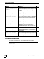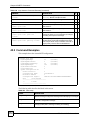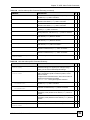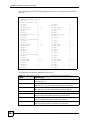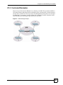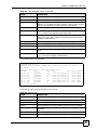
1
VES Switch
VDSL Switch
CLI Reference Guide
Versions 3.60, 3.70, 3.80
3/2010
Edition 2
DEFAULT LOGIN
IP Address http://192.168.0.1 (Out-of-band MGMT port)
http://192.168.1.1 (In-band ports)
User Name admin
Password
1234
www.zyxel.com
About This User's Guide
About This User's Guide
Intended Audience
This manual is intended for people who want to configure the VES series via commands. You
should have at least a basic knowledge of TCP/IP networking concepts and topology.
The version number on the cover page refers to the latest firmware version supported by the
ZyXEL VES Switch. This guide covers the following models at the time of writing.
"
VES-1616FA-44
VES-1624FA-44
VES-1616FA-54
VES-1624FA-54
VES-1608FC-44
VES-1616FC-44
VES-1616CTA-54
VES-1624CTA-54
VES-1608PE-35
VES1616FT-54
VES1624FT-54
VES-1616PE-54
VES-1616CTA+
VES-1624CTA+
VES-1608FA-3x
VES-1616FB-35
This guide is intended as a command reference for a series of products.
Therefore many commands in this guide may not be available in your product.
See your User’s Guide for a list of supported features and details about feature
implementation.
Please refer to www.zyxel.com or your product’s CD for product specific User Guides and
product certifications.
CLI Reference Guide Feedback
Help us help you. Send all Reference Guide-related comments, questions or suggestions for
improvement to the following address, or use e-mail instead. Thank you!
The Technical Writing Team,
ZyXEL Communications Corp.,
6 Innovation Road II,
Science-Based Industrial Park,
Hsinchu, 300, Taiwan.
E-mail: [email protected]
VES Switch CLI Reference Guide
3
About This User's Guide
Customer Support
In the event of problems that cannot be solved by using this manual, you should contact your
vendor. If you cannot contact your vendor, then contact a ZyXEL office for the region in
which you bought the device. See http://www.zyxel.com/web/contact_us.php for contact
information. Please have the following information ready when you contact an office.
•
•
•
•
4
Product model and serial number.
Warranty Information.
Date that you received your device.
Brief description of the problem and the steps you took to solve it.
VES Switch CLI Reference Guide
Document Conventions
Document Conventions
Warnings and Notes
These are how warnings and notes are shown in this User’s Guide.
1
"
Warnings tell you about things that could harm you or your device.
Notes tell you other important information (for example, other things you may
need to configure or helpful tips) or recommendations.
Syntax Conventions
This manual follows these general conventions:
• The VES series may be referred to as the “Switch”, the “system”, the “device”, or the
“product” in this Reference Guide. Differentiation between models is made where needed.
• Units of measurement may denote the “metric” value or the “scientific” value. For
example, “k” for kilo may denote “1000” or “1024”, “M” for mega may denote “1000000”
or “1048576” and so on.
Command descriptions follow these conventions:
• Commands are in courier new font.
• Required input values are in angle brackets <>; for example, ping <ip> means that you
must specify an IP address for this command.
• Optional fields are in square brackets []; for instance show logins [name], the name
field is optional.
The following is an example of a required field within an optional field: snmp-server
[contact <system contact>], the contact field is optional. However, if you
use contact, then you must provide the system contact information.
• Lists (such as <port-list>) consist of one or more elements separated by commas.
Each element might be a single value (1, 2, 3, ...) or a range of values (1-2, 3-5, ...)
separated by a dash.
• The | (bar) symbol means “or”.
• italic terms represent user-defined input values; for example, in snmp-server
[contact <system contact>], system contact can be replaced by the
administrator’s name.
• A key stroke is denoted by square brackets and uppercase text, for example, [ENTER]
means the “Enter” or “Return” key on your keyboard
• <cr> means press the [ENTER] key.
VES Switch CLI Reference Guide
5
Document Conventions
• An arrow (-->) indicates that this line is a continuation of the previous line.
Icons Used in Figures
Figures in this User’s Guide may use the following generic icons. The Switch icon is not an
exact representation of your device.
6
Switch
Computer
Server
Notebook computer
DSLAM
Gateway
Central Office/ ISP
Internet
Hub/Switch
VES Switch CLI Reference Guide
Safety Warnings
Safety Warnings
1
See the appropriate User’s Guide for safety warnings.
VES Switch CLI Reference Guide
7
Safety Warnings
8
VES Switch CLI Reference Guide
Contents Overview
Contents Overview
Introduction ............................................................................................................................ 13
Getting Started ........................................................................................................................... 15
Privilege Level and Command Mode ......................................................................................... 19
Initial Setup ................................................................................................................................ 23
Reference ................................................................................................................................ 27
How to Use This Guide .............................................................................................................. 31
AAA Commands ........................................................................................................................ 33
ARP Commands ........................................................................................................................ 37
ARP Inspection Commands ...................................................................................................... 39
Bandwidth Commands .............................................................................................................. 45
Broadcast Storm Commands ..................................................................................................... 47
CFM commands ........................................................................................................................ 49
Classifier Commands ................................................................................................................ 57
Cluster Commands .................................................................................................................... 59
Date and Time Commands ........................................................................................................ 63
DHCP Commands ..................................................................................................................... 67
DHCP Snooping & DHCP VLAN Commands ............................................................................ 73
DiffServ Commands ................................................................................................................... 77
DoS Prevention Commands ...................................................................................................... 79
Ethernet OAM Commands ........................................................................................................ 81
External Alarm Commands ........................................................................................................ 87
GARP Commands ..................................................................................................................... 89
GPON Command ...................................................................................................................... 91
GVRP Commands ..................................................................................................................... 93
HTTPS Server Commands ........................................................................................................ 95
IEEE 802.1x Authentication Commands ................................................................................... 99
IGMP Commands .................................................................................................................... 101
IGMP Filtering Commands ...................................................................................................... 107
Ingress Check Commands ...................................................................................................... 109
Interface Commands ................................................................................................................111
IP Commands .......................................................................................................................... 121
IPQoS Commands ................................................................................................................... 127
IP Source Binding Commands ................................................................................................ 129
IPv6 Commands ...................................................................................................................... 131
Layer 2 Protocol Tunnel (L2PT) Commands ........................................................................... 145
LACP Commands .................................................................................................................... 149
Login Account Commands ...................................................................................................... 151
VES Switch CLI Reference Guide
9
Contents Overview
Login Precedence Commands ................................................................................................ 153
Loopguard Commands ............................................................................................................ 155
MAC Address Commands ....................................................................................................... 157
MAC Authentication Commands ............................................................................................. 159
MAC-based VLAN Commands ................................................................................................ 161
MAC Filter Commands ............................................................................................................ 163
MAC Forward Commands ....................................................................................................... 165
Mirror Commands .................................................................................................................... 167
MRSTP Commands ................................................................................................................. 169
MSTP Commands ................................................................................................................... 171
Multiple Login Commands ....................................................................................................... 175
MVR Commands ..................................................................................................................... 177
Password Commands ............................................................................................................. 179
Policy Commands .................................................................................................................... 181
Port Security Commands ......................................................................................................... 185
Port-based VLAN Commands ................................................................................................. 187
PPPoE Intermediate Agent Commands .................................................................................. 189
Protocol-based VLAN Commands ........................................................................................... 193
RADIUS Commands ................................................................................................................ 197
Rate Limit Commands ............................................................................................................. 199
Remote CPE Device Commands ............................................................................................ 203
Remote Management Commands ........................................................................................... 225
Running Configuration Commands ......................................................................................... 227
Service Control Commands ..................................................................................................... 229
SNMP Server Commands ....................................................................................................... 231
SSH Commands ...................................................................................................................... 235
Static Multicast Commands ..................................................................................................... 237
Static Route Commands .......................................................................................................... 239
STP and RSTP Commands ..................................................................................................... 241
Subnet-based VLAN Commands ............................................................................................ 245
Syslog Commands .................................................................................................................. 247
TACACS+ Commands ............................................................................................................. 249
TFTP Commands .................................................................................................................... 251
Trunk Commands .................................................................................................................... 253
trTCM Commands ................................................................................................................... 255
VDSL Alarm Profile Commands .............................................................................................. 257
VDSL Counters Commands .................................................................................................... 261
VDSL Loop Diagnostic Commands ......................................................................................... 267
VDSL Profile Commands ......................................................................................................... 271
VDSL Settings Commands ...................................................................................................... 289
VLAN Commands .................................................................................................................... 293
VLAN Mapping Commands ..................................................................................................... 297
VLAN Port Isolation Commands .............................................................................................. 299
10
VES Switch CLI Reference Guide
Contents Overview
VLAN-Profile Commands ........................................................................................................ 301
VLAN-Security Commands ...................................................................................................... 303
VLAN Stacking Commands ..................................................................................................... 305
VLAN Translation ......................................................................................................................311
VLAN Trunking Commands ..................................................................................................... 315
Additional Commands ............................................................................................................. 317
Appendices and Index ......................................................................................................... 327
VES Switch CLI Reference Guide
11
Contents Overview
12
VES Switch CLI Reference Guide
P ART I
Introduction
Getting Started (15)
Privilege Level and Command Mode (19)
Initial Setup (23)
13
14
CHAPTER
1
Getting Started
This chapter introduces the command line interface (CLI).
1.1 Accessing the CLI
Use any of the following methods to access the CLI.
1.1.1 Console Port
1 Connect your computer to the console port on the Switch using the appropriate cable.
2 Use terminal emulation software with the following settings:
Table 1 Default Settings for the Console Port
SETTING
DEFAULT VALUE
Terminal Emulation
VT100
Baud Rate
9600 bps
Parity
None
Number of Data Bits
8
Number of Stop Bits
1
Flow Control
None
3 Press [ENTER] to open the login screen.
1.1.2 Telnet
1 Connect your computer to the MGMT port.
2 Open a Telnet session to the Switch’s IP address. If this is your first login, use the default
values.
Table 2 Default Management IP Address
SETTING
DEFAULT VALUE
IP Address
192.168.0.1
Subnet Mask
255.255.255.0
Make sure your computer IP address is in the same subnet, unless you are accessing the
Switch through one or more routers.
VES Switch CLI Reference Guide
15
Chapter 1 Getting Started
1.1.3 SSH
1 Connect your computer to the MGMT port.
2 Use a SSH client program to access the Switch. If this is your first login, use the default
values in Table 2 on page 15 and Table 3 on page 16. Make sure your computer IP
address is in the same subnet, unless you are accessing the Switch through one or more
routers.
1.2 Logging in
Use the administrator username and password. If this is your first login, use the default values.
Table 3 Default User Name and Password
"
SETTING
DEFAULT VALUE
User Name
admin
Password
1234
The Switch automatically logs you out of the management interface after five
minutes of inactivity. If this happens to you, simply log back in again.
1.3 Using Shortcuts and Getting Help
This table identifies some shortcuts in the CLI, as well as how to get help.
Table 4 CLI Shortcuts and Help
COMMAND / KEY(S)
DESCRIPTION
history
Displays a list of recently-used commands.
yz (up/down arrow keys)
Scrolls through the list of recently-used commands. You can edit
any command or press [ENTER] to run it again.
[CTRL]+Z
Returns to the previous mode. See Chapter 2 on page 19 for more
information about modes.
[CTRL]+U
Clears the current command.
[TAB]
Auto-completes the keyword you are typing if possible. For
example, type config, and press [TAB]. The Switch finishes the
word configure.
?
Displays the keywords and/or input values that are allowed in
place of the ?.
help
Displays the (full) commands that are allowed in place of help.
The help generally follows these syntax conventions:
• Each interface refers to a port on the Switch.
• Required input values are in angle brackets <>; for example, ping <ip-address>
means that you must specify an IP number for this command.
16
VES Switch CLI Reference Guide
Chapter 1 Getting Started
• Lists (such as <port-list>) consist of one or more elements separated by commas.
Each element might be a single value (1, 2, 3, ...) or a range of values (1-2, 3-5, ...)
separated by a dash. Use an asterisk (*) to indicate all possible elements.
• The | (bar) symbol means “or”.
• Optional fields are in square brackets []; for instance, in snmp-server [contact
<system contact>] [location <system location>], the contact and
location fields are optional.
• The <cr> means press the [ENTER] key.
1.4 Saving Your Configuration
When you run a command, the Switch saves any changes to its run-time memory. The Switch
loses these changes if it is turned off or loses power. Use the write memory command in
enable mode to save the current configuration permanently to non-volatile memory.
sysname# write memory
"
You should save your changes after each CLI session. All unsaved
configuration changes are lost once you restart the Switch.
1.5 Logging Out
Enter logout to log out of the CLI. You have to be in user, enable, or config mode. See
Chapter 2 on page 19 for more information about modes.
VES Switch CLI Reference Guide
17
Chapter 1 Getting Started
18
VES Switch CLI Reference Guide
CHAPTER
2
Privilege Level and Command
Mode
This chapter introduces privilege levels and the command modes that are available in the CLI.
• The privilege level determines whether or not a user can run a particular command.
• If a user can run a particular command, the user has to run it in the correct mode.
2.1 Privilege Levels
Every command has a privilege level (0-14). Users can run a command if the session’s
privilege level is greater than or equal to the command’s privilege level. The session’s
privilege level initially comes from the login account’s privilege level, though it is possible to
change the session’s privilege level after logging in.
2.1.1 Privilege Levels for Commands
The privilege level of each command is listed in the corresponding command summary table.
At the time of writing, commands have a privilege level of 0, 3, 13, or 14. The following table
summarizes the types of commands at each of these privilege levels.
Table 5 Types of Commands at Different Privilege Levels
PRIVILEGE LEVEL
TYPES OF COMMANDS AT THIS PRIVILEGE LEVEL
0
Display basic system information.
3
Display configuration or status.
13
Configure features except for login accounts, login precedence, multiple logins,
and administrator and enable passwords.
14
Configure login accounts, login precedence, multiple logins, and administrator
and enable passwords.
2.1.2 Privilege Levels for Login Accounts
You can manage the privilege levels for login accounts the following ways:
• Use commands. Login accounts can be configured by the admin account or any login
account with a privilege level of 14. See Chapter 35 on page 151.
• Use vendor-specific attributes in an external authentication servers. See the User’s Guide
for more information.
VES Switch CLI Reference Guide
19
Chapter 2 Privilege Level and Command Mode
The admin account has a privilege level of 14, so the administrator can run every command.
You cannot change the privilege level of the admin account.
2.1.3 Privilege Levels for Sessions
The session’s privilege level initially comes from the privilege level of the login account the
user used to log in to the Switch. After logging in, the user can use the following commands to
change the session’s privilege level.
2.1.3.1 enable
This command raises the session’s privilege level to 14. It also changes the session to enable
mode, if necessary. This command is available in user mode or enable mode, and users have to
know the enable password.
In the following example, the login account user0 has a privilege level of 0 but knows that the
enable password is 123456. Afterwards, the session’s privilege level is 14, instead of 0, and
the session changes to enable mode.
sysname> enable
Password: 123456
sysname#
The default enable password is 1234. Use this command to set the enable password.
password <password>
<password> consists of 1-32 alphanumeric characters. For example, the following command
sets the enable password to 123456. See Chapter 84 on page 317 for more information about
this command.
sysname(config)# password 123456
2.1.3.2 enable <0-14> Command
This command raises the session’s privilege level to the specified level. It also changes the
session to enable mode, if the specified level is 13 or 14. This command is available in user
mode or enable mode, and users have to know the password for the specified privilege level.
In the following example, the login account user0 has a privilege level of 0 but knows that the
password for privilege level 13 is pswd13. Afterwards, the session’s privilege level is 13,
instead of 0, and the session changes to enable mode.
sysname> enable 13
Password: pswd13
sysname#
Users cannot use this command until you create passwords for specific privilege levels. Use
the following command to create passwords for specific privilege levels.
password <password> privilege <0-14>
20
VES Switch CLI Reference Guide
Chapter 2 Privilege Level and Command Mode
<password> consists of 1-32 alphanumeric characters. For example, the following
command sets the password for privilege level 13 to pswd13. See Chapter 48 on page 179 for
more information about this command.
sysname(config)# password pswd13 privilege 13
2.1.3.3 disable
This command reduces the session’s privilege level to 0. It also changes the session to user
mode. This command is available in enable mode.
2.2 Command Modes
The CLI is divided into several modes. If a user has enough privilege to run a particular
command, the user has to run the command in the correct mode. The modes that are available
depend on the session’s privilege level.
2.2.1 Command Modes for Privilege Levels 0-12
If the session’s privilege level is 0-12, the user and all of the commands are in user mode.
Users do not have to change modes to run any allowed commands.
2.2.2 Command Modes for Privilege Levels 13-14
If the session’s privilege level is 13-14, the allowed commands are in one of several modes.
Table 6 Command Modes for Privilege Levels 13-14 and the Types of Commands in Each One
MODE
PROMPT
TYPES OF COMMANDS IN THIS MODE
enable
sysname#
Displays current configuration, diagnostics, maintenance.
config
sysname(config)#
Configures features other than those below.
config-interface
sysname(config-interface)#
Configures ports.
config-mvr
sysname(config-mvr)#
Configures multicast VLAN.
config-port
sysname(config-port)#
Configures VLAN port isolation.
config-RmtVtur
sysname(config-RmtVtur)#
Configures remote (CPE) devices.
config-vdslalarmprofile
sysname(configvdslalarmprofile)#
Configures VDSL alarm profiles.
config-vdsl-profile sysname(configvdslprofile)#
Configures VDSL profiles.
config-vlan
Configures static VLAN.
sysname(config-vlan)#
VES Switch CLI Reference Guide
21
Chapter 2 Privilege Level and Command Mode
Each command is usually in one and only one mode. If a user wants to run a particular
command, the user has to change to the appropriate mode. The command modes are organized
like a tree, and users start at the root of the tree in enable mode. The following table explains
how to change from one mode to another.
Table 7 Changing Between Command Modes for Privilege Levels 13-14
MODE
ENTER MODE
LEAVE MODE
enable
--
--
configure
exit
config-interface
interface port-channel <port-list>
exit
config-mvr
mvr <vlan-id>
exit
config-port
vlan1q port-isolation <port-list>
exit
config-vdsl-alarmprofile
vdsl-alarmprofile <profile-name>
exit
config-vdsl-profile
vdsl-profile <profile-name>
exit
config-vlan
vlan <vlan-id>
exit
rmt-vtur port-channel <port-list>
exit
config
config-RmtVtur
22
VES Switch CLI Reference Guide
CHAPTER
3
Initial Setup
This chapter identifies tasks you might want to do when you first configure the Switch.
3.1 Changing the Administrator Password
"
It is recommended you change the default administrator password.
Use this command to change the administrator password.
admin-password <password> <confirm-password>
where <password> and <confirm-password> may be 1-32 alphanumeric characters long.
sysname# configure
sysname(config)# admin-password t1g2y7i9 t1g2y7i9
3.2 Changing the Enable Password
"
It is recommended you change the default enable password.
Use this command to change the enable password.
password <password>
where <password> may be 1-32 alphanumeric characters long.
sysname# configure
sysname(config)# password k8s8s3dl0
VES Switch CLI Reference Guide
23
Chapter 3 Initial Setup
3.3 Prohibiting Concurrent Logins
By default, multiple CLI sessions are allowed via the console port or Telnet. See the User’s
Guide for the maximum number of concurrent sessions for your Switch. Use this command to
prohibit concurrent logins.
no multi-login
Console port has higher priority than Telnet. See Chapter 46 on page 175 for more multilogin commands.
sysname# configure
sysname(config)# no multi-login
3.4 Changing the Management IP Address
Use this command to change the management IP address when you are connected to the
MGMT port.
ip address <ip-address> <mask>
or
ip outband address <ip-address> <mask>
This example shows you how to change the out-of-band management IP address to 172.1.1.10
with subnet mask 255.255.255.0.
sysname# configure
sysname(config)# ip address 172.1.1.10 255.255.255.0
or
sysname# configure
sysname(config)# ip outband address 172.1.1.10 255.255.255.0
"
Afterwards, you have to use the new IP address to access the Switch.
Use this command to change the management IP address when you are connected to any other
ports.
vlan <vlan-id> ip address inband-default <ip-address> <mask>
or
ip inband address <ip-address> <mask>
Alternatively, use this command if you want the Switch can get the in-band management IP
address from a DHCP server.
vlan <vlan-id> ip address inband-default dhcp-bootp
24
VES Switch CLI Reference Guide
Chapter 3 Initial Setup
or
ip inband client
3.5 Looking at Basic System Information
Use this command to look at general system information about the Switch.
show system-information
This is illustrated in the following example.
sysname# show system-information
System Name
System Contact
System Location
Ethernet Address
ZyNOS F/W Version
RomRasSize
System up Time
Bootbase Version
Power info
Product Model
:
:
:
:
:
:
:
:
:
:
VES-1616FA-54
00:19:cb:00:00:02
V3.50(AYG.2)b4 | 03/13/2008
3581028
0:16:44 (18869 ticks)
V0.2 | 06/08/2007
N/A
VES-1616FA-54
See Chapter 84 on page 317 for more information about these attributes.
3.6 Looking at the Operating Configuration
Use this command to look at the current operating configuration.
show running-config
This is illustrated in the following example.
sysname# show running-config
Building configuration...
Current configuration:
vlan 1
name 1
normal ""
fixed 1-18
forbidden ""
untagged 1-18
exit
interface port-channel 1
igmp-querier-mode edge
broadcast-limit 262143
exit
--------------------------------- SNIP ---------------------------------
VES Switch CLI Reference Guide
25
Chapter 3 Initial Setup
26
VES Switch CLI Reference Guide
P ART II
Reference
How to Use This Guide (31)
Bandwidth Commands (45)
Broadcast Storm Commands (47)
CFM commands (49)
Classifier Commands (57)
Cluster Commands (59)
Date and Time Commands (63)
DHCP Commands (67)
DHCP Snooping & DHCP VLAN Commands (73)
DiffServ Commands (77)
DoS Prevention Commands (79)
Ethernet OAM Commands (81)
External Alarm Commands (87)
GARP Commands (89)
GPON Command (91)
GVRP Commands (93)
HTTPS Server Commands (95)
IEEE 802.1x Authentication Commands (99)
IGMP Commands (101)
IGMP Filtering Commands (107)
Ingress Check Commands (109)
Interface Commands (111)
IP Commands (121)
27
IPQoS Commands (127)
IP Source Binding Commands (129)
IPv6 Commands (131)
Layer 2 Protocol Tunnel (L2PT) Commands (145)
LACP Commands (149)
Login Account Commands (151)
Login Precedence Commands (153)
Loopguard Commands (155)
MAC Address Commands (157)
MAC Authentication Commands (159)
MAC-based VLAN Commands (161)
MAC Filter Commands (163)
MAC Forward Commands (165)
Mirror Commands (167)
MRSTP Commands (169)
MSTP Commands (171)
Multiple Login Commands (175)
MVR Commands (177)
Password Commands (179)
Policy Commands (181)
Port Security Commands (185)
Port-based VLAN Commands (187)
Protocol-based VLAN Commands (193)
RADIUS Commands (197)
Rate Limit Commands (199)
Remote CPE Device Commands (203)
Remote Management Commands (225)
Running Configuration Commands (227)
Service Control Commands (229)
SNMP Server Commands (231)
SSH Commands (235)
Static Multicast Commands (237)
Static Route Commands (239)
STP and RSTP Commands (241)
Subnet-based VLAN Commands (245)
Syslog Commands (247)
28
TACACS+ Commands (249)
TFTP Commands (251)
Trunk Commands (253)
trTCM Commands (255)
VDSL Alarm Profile Commands (257)
VDSL Counters Commands (261)
VDSL Loop Diagnostic Commands (267)
VDSL Profile Commands (271)
VDSL Settings Commands (289)
VLAN Commands (293)
VLAN Mapping Commands (297)
VLAN Port Isolation Commands (299)
VLAN-Profile Commands (301)
VLAN-Security Commands (303)
VLAN Stacking Commands (305)
VLAN Translation (311)
VLAN Trunking Commands (315)
Additional Commands (317)
29
30
CHAPTER
4
How to Use This Guide
This chapter explains how commands are introduced in this guide.
4.1 Background Information (Optional)
"
See the User’s Guide for background information about most features.
This section provides background information about features that you cannot configure in the
Web Configurator. In addition, this section identifies related commands in other chapters.
4.2 Command Summary
The following table describes user-input values available in multiple commands for this
feature.
Table 8 Example: User-input Values
COMMAND
DESCRIPTION
vlan-id
1~4094
This section lists the commands for this feature in one or more tables.
Table 9 Example: Command Summary Table
COMMAND
DESCRIPTION
M
P
show vlan
Displays the status of all VLANs.
E
3
vlan <vlan-id>
Enters config-vlan mode for the specified VLAN. Creates the
VLAN, if necessary.
C
13
inactive
Disables the specified VLAN.
C
13
no inactive
Enables the specified VLAN.
C
13
Deletes a VLAN.
C
13
no vlan <vlan-id>
The Table title identifies the specific keyword(s) that the commands share.
The Command column shows the syntax of the command. The syntax follows the same
conventions the help (Section 1.3 on page 16) does, in addition to the following.
VES Switch CLI Reference Guide
31
Chapter 4 How to Use This Guide
• these terms represent user-input values that are explained in more detail in the
Description column or in the user-input value table.
• If a command is indented, users have to run it in one of the config- modes. You can
identify the specific mode by looking at the last config-mode command above it.
• If a command is not indented, users have to run it in enable or config mode.
The Description column explains what the command does. It also identifies legal input values
for user-input values, if necessary.
The M column helps identify the mode in which users have to run the command.
• E: The command is available in enable mode. It is also available in user mode if the
privilege level (P) is less than 13.
• C: The command is available in config (not indented) or one of the config- (indented)
modes.
The P column identifies the privilege level of the command.
4.3 Command Examples (Optional)
This section contains any examples for the commands in this feature.
32
VES Switch CLI Reference Guide
CHAPTER
5
AAA Commands
Use these commands to configure authentication, authorization and accounting on the Switch.
5.1 Command Summary
The following section lists the commands for this feature.
Table 10 aaa authentication Command Summary
COMMAND
DESCRIPTION
M
P
show aaa authentication
Displays what methods are used for authentication.
E
13
show aaa authentication enable
Displays the authentication method(s) for checking privilege
level of administrators.
E
13
aaa authentication enable
<method1> [<method2> ...]
Specifies which method should be used first, second, and
third for checking users’ privileges for settings.
method: local, radius, or tacacs+.
C
13
no aaa authentication enable
Resets the method list for checking privileges to its default
value.
C
13
show aaa authentication login
Displays the authentication methods for administrator login
accounts.
E
13
aaa authentication login
<method1> [<method2> ...]
Specifies which method should be used first, second, and
third for the authentication of login accounts. This is used to
determine a user can log into the Switch or not.
method: local, radius, or tacacs+.
C
13
no aaa authentication login
Resets the method list for the authentication of login accounts
to its default value.
C
13
Table 11 aaa accounting Command Summary
COMMAND
DESCRIPTION
M
P
show aaa accounting
Displays accounting settings configured on the Switch.
E
3
show aaa accounting update
Display the update period setting on the Switch for
accounting sessions.
E
3
aaa accounting update periodic
<1-2147483647>
Sets the update period (in minutes) for accounting sessions.
This is the time the Switch waits to send an update to an
accounting server after a session starts.
C
13
no aaa accounting update
Resets the accounting update interval to the default value.
C
13
show aaa accounting commands
Displays accounting settings for recording command events.
E
3
VES Switch CLI Reference Guide
33
Chapter 5 AAA Commands
Table 11 aaa accounting Command Summary (continued)
COMMAND
DESCRIPTION
M
P
aaa accounting commands
<privilege> stop-only tacacs+
[broadcast]
Enables accounting of command sessions and specifies the
minimum privilege level (0-14) for the command sessions that
should be recorded. Optionally, sends accounting information
for command sessions to all configured accounting servers at
the same time.
C
13
no aaa accounting commands
Disables accounting of command sessions on the Switch.
C
13
show aaa accounting dot1x
Displays accounting settings for recording IEEE 802.1x
session events.
E
3
aaa accounting dot1x <startstop|stop-only>
<radius|tacacs+> [broadcast]
Enables accounting of IEEE 802.1x authentication sessions
and specifies the mode and protocol method. Optionally,
sends accounting information for IEEE 802.1x authentication
sessions to all configured accounting servers at the same
time.
C
13
no aaa accounting dot1x
Disables accounting of IEEE 802.1x authentication sessions
on the Switch.
C
13
show aaa accounting exec
Displays accounting settings for recording administrative
sessions via SSH, Telnet or the console port.
E
3
aaa accounting exec <startstop|stop-only>
<radius|tacacs+> [broadcast]
Enables accounting of administrative sessions via SSH,
Telnet and console port and specifies the mode and protocol
method. Optionally, sends accounting information for
administrative sessions via SSH, Telnet and console port to
all configured accounting servers at the same time.
C
13
no aaa accounting exec
Disables accounting of administrative sessions via SSH,
Telnet or console on the Switch.
C
13
show aaa accounting system
Displays accounting settings for recording system events, for
example system shut down, start up, accounting enabled or
accounting disabled.
E
3
aaa accounting system
<radius|tacacs+> [broadcast]
Enables accounting of system events and specifies the
protocol method. Optionally, sends accounting information for
system events to all configured accounting servers at the
same time.
C
13
no aaa accounting system
Disables accounting of system events on the Switch.
C
13
5.2 Command Examples
This example displays how to show the current authentication method settings.
sysname# show aaa authentication
Authentication:
Type
Method 1
Method 2
Enable
local
Login
local
-
34
Method 3
-
VES Switch CLI Reference Guide
Chapter 5 AAA Commands
This example displays how to sets the authentication methods first to use radius server and
second to use the Switch’s local database.
sysname# configure
sysname(config)# aaa authentication enable radius local
sysname(config)# aaa authentication login radius local
sysname(config)# exit
sysname# show aaa authentication
Authentication:
Type
Method 1
Method 2
Method 3
Enable
radius
local
Login
radius
local
sysname#
VES Switch CLI Reference Guide
35
Chapter 5 AAA Commands
36
VES Switch CLI Reference Guide
CHAPTER
6
ARP Commands
Use these commands to look at IP-to-MAC address mapping(s).
6.1 Command Summary
The following section lists the commands for this feature.
Table 12 arp Command Summary
COMMAND
DESCRIPTION
M
P
show ip arp
Displays the ARP table.
E
13
no arp
Flushes the ARP table entries.
E
13
6.2 Command Examples
This example shows the ARP table.
sysname# show ip arp
Index
IP
1
172.16.10.254
MAC
00:04:80:9b:78:00
VLAN
1
Age(s)
300
Type
dynamic
The following table describes the labels in this screen.
Table 13 show ip arp
LABEL
DESCRIPTION
Index
This field displays the index number.
IP
This field displays the learned IP address of the device.
MAC
This field displays the MAC address of the device.
VLAN
This field displays the VLAN to which the device belongs.
Age(s)
This field displays how long the entry remains valid.
Type
This field displays how the entry was learned.
dynamic: The Switch learned this entry from ARP packets.
VES Switch CLI Reference Guide
37
Chapter 6 ARP Commands
38
VES Switch CLI Reference Guide
CHAPTER
7
ARP Inspection Commands
Use these commands to filter unauthorized ARP packets in your network.
7.1 Command Summary
The following section lists the commands for this feature.
Table 14 arp inspection Command Summary
COMMAND
DESCRIPTION
M
P
show arp inspection
Displays ARP inspection configuration details.
E
3
arp inspection
Enables ARP inspection on the Switch. You still have to
enable ARP inspection on specific VLAN and specify trusted
ports.
C
13
no arp inspection
Disables ARP inspection on the Switch.
C
13
clear arp inspection statistics
Removes all ARP inspection statistics on the Switch.
E
3
clear arp inspection statistics
vlan <vlan-list>
Removes ARP inspection statistics for the specified VLAN(s). E
3
show arp inspection statistics
Displays all ARP inspection statistics on the Switch.
E
3
show arp inspection statistics
vlan <vlan-list>
Displays ARP inspection statistics for the specified VLAN(s).
E
3
Table 15 Command Summary: arp inspection filter
COMMAND
DESCRIPTION
M
P
show arp inspection filter
[<mac-addr>] [vlan <vlan-id>]
Displays the current list of MAC address filters that were
created because the Switch identified an unauthorized ARP
packet. Optionally, lists MAC address filters based on the
MAC address or VLAN ID in the filter.
E
3
no arp inspection filter <macaddr> vlan <vlan-id>
Specifies the ARP inspection record you want to delete from
the Switch. The ARP inspection record is identified by the
MAC address and VLAN ID pair.
E
13
clear arp inspection filter
Delete all ARP inspection filters from the Switch.
E
13
arp inspection filter-aging-time
<1-2147483647>
Specifies how long (1-2147483647 seconds) MAC address
filters remain in the Switch after the Switch identifies an
unauthorized ARP packet. The Switch automatically deletes
the MAC address filter afterwards.
C
13
arp inspection filter-aging-time
none
Specifies the MAC address filter to be permanent.
C
13
no arp inspection filter-agingtime
Resets how long (1-2147483647 seconds) the MAC address
filter remains in the Switch after the Switch identifies an
unauthorized ARP packet to the default value.
C
13
VES Switch CLI Reference Guide
39
Chapter 7 ARP Inspection Commands
Table 16 Command Summary: arp inspection log
COMMAND
DESCRIPTION
M
P
show arp inspection log
Displays the log settings configured on the Switch. It also
displays the log entries recorded on the Switch.
E
3
clear arp inspection log
Delete all ARP inspection log entries from the Switch.
E
13
arp inspection log-buffer
entries <0-1024>
Specifies the maximum number (1-1024) of log messages
that can be generated by ARP packets and not sent to the
syslog server.
If the number of log messages in the Switch exceeds this
number, the Switch stops recording log messages and simply
starts counting the number of entries that were dropped due
to unavailable buffer.
C
13
arp inspection log-buffer logs
<0-1024> interval <0-86400>
Specifies the number of syslog messages that can be sent to
the syslog server in one batch and how often (1-86400
seconds) the Switch sends a batch of syslog messages to the
syslog server.
C
13
no arp inspection log-buffer
entries
Resets the maximum number (1-1024) of log messages that
can be generated by ARP packets and not sent to the syslog
server to the default value.
C
13
no arp inspection log-buffer
logs
Resets the maximum number of syslog messages the Switch
can send to the syslog server in one batch to the default
value.
C
13
Table 17 Command Summary: interface arp inspection
COMMAND
DESCRIPTION
M
P
show arp inspection interface
port-channel <port-list>
Displays the ARP inspection settings for the specified port(s). E
3
interface port-channel <portlist>
Enters config-interface mode for the specified port(s).
C
13
arp inspection trust
Sets the port to be a trusted port for arp inspection. The
Switch does not discard ARP packets on trusted ports for any
reason.
C
13
no arp inspection trust
Disables this port from being a trusted port for ARP
inspection.
C
13
arp inspection limit rate
<pps> [burst interval
<seconds>]
Sets a rate limit (in pps, packets per second) for ARP packets
on the port. You can also set the burst interval (in seconds)
over which the rate of ARP packets is monitored.
C
13
no arp inspection limit
Disables the rate limit for ARP packets.
C
13
Table 18 Command Summary: arp inspection vlan
COMMAND
DESCRIPTION
M
P
show arp inspection vlan <vlanlist>
Displays ARP inspection settings for the specified VLAN(s).
E
3
arp inspection vlan <vlan-list>
Enables ARP inspection on the specified VLAN(s).
C
13
no arp inspection vlan <vlanlist>
Disables ARP inspection on the specified VLAN(s).
C
13
arp inspection vlan <vlan-list>
logging [all|none|permit|deny]
Enables logging of ARP inspection events on the specified
VLAN(s). Optionally specifies which types of events to log.
C
13
no arp inspection vlan <vlanlist> logging
Disables logging of messages generated by ARP inspection
for the specified VLAN(s).
C
13
40
VES Switch CLI Reference Guide
Chapter 7 ARP Inspection Commands
7.2 Command Examples
This example looks at the current list of MAC address filters that were created because the
Switch identified an unauthorized ARP packet. When the Switch identifies an unauthorized
ARP packet, it automatically creates a MAC address filter to block traffic from the source
MAC address and source VLAN ID of the unauthorized ARP packet.
sysname# show arp inspection filter
Filtering aging timeout : 300
MacAddress VLAN
Port
----------------- ---- ----Total number of bindings: 0
Expiry (sec)
------------
Reason
--------------
The following table describes the labels in this screen.
Table 19 show arp inspection filter
LABEL
DESCRIPTION
Filtering aging timeout
This field displays how long the MAC address filters remain in the Switch
after the Switch identifies an unauthorized ARP packet. The Switch
automatically deletes the MAC address filter afterwards.
MacAddress
This field displays the source MAC address in the MAC address filter.
VLAN
This field displays the source VLAN ID in the MAC address filter.
Port
This field displays the source port of the discarded ARP packet.
Expiry (sec)
This field displays how long (in seconds) the MAC address filter remains in
the Switch. You can also delete the record manually (Delete).
Reason
This field displays the reason the ARP packet was discarded.
MAC+VLAN: The MAC address and VLAN ID were not in the binding table.
IP: The MAC address and VLAN ID were in the binding table, but the IP
address was not valid.
Port: The MAC address, VLAN ID, and IP address were in the binding
table, but the port number was not valid.
This example looks at log messages that were generated by ARP packets and that have not
been sent to the syslog server yet.
sysname# show arp inspection log
Total Log Buffer Size : 32
Syslog rate : 5 entries per 1 seconds
Port
Vlan
Sender MAC
Time
---- ---- ------------------------------------Total number of logs: 0
VES Switch CLI Reference Guide
Sender IP
Pkts
Reason
---------------
----
----------
----
41
Chapter 7 ARP Inspection Commands
The following table describes the labels in this screen.
Table 20 show arp inspection log
LABEL
DESCRIPTION
Total Log Buffer Size
This field displays the maximum number (1-1024) of log messages that
were generated by ARP packets and have not been sent to the syslog
server yet.
If the number of log messages in the Switch exceeds this number, the
Switch stops recording log messages and simply starts counting the
number of entries that were dropped due to unavailable buffer.
Syslog rate
This field displays the maximum number of syslog messages the Switch
can send to the syslog server in one batch. This number is expressed as a
rate because the batch frequency is determined by the Log Interval.
Port
This field displays the source port of the ARP packet.
Vlan
This field displays the source VLAN ID of the ARP packet.
Sender MAC
This field displays the source MAC address of the ARP packet.
Sender IP
This field displays the source IP address of the ARP packet.
Pkts
This field displays the number of ARP packets that were consolidated into
this log message. The Switch consolidates identical log messages
generated by ARP packets in the log consolidation interval into one log
message.
Reason
This field displays the reason the log message was generated.
static deny: An ARP packet was discarded because it violated a static
binding with the same MAC address and VLAN ID.
deny: An ARP packet was discarded because there were no bindings with
the same MAC address and VLAN ID.
static permit: An ARP packet was forwarded because it matched a static
binding.
Time
This field displays when the log message was generated.
Total number of logs
This field displays the number of log messages that were generated by
ARP packets and that have not been sent to the syslog server yet. If one or
more log messages are dropped due to unavailable buffer, there is an entry
called overflow with the current number of dropped log messages.
This example displays whether ports are trusted or untrusted ports for ARP inspection.
sysname# show arp inspection interface port-channel 1
Interface Trusted State Rate (pps) Burst Interval
--------- ------------- ---------- -------------1
Untrusted
15
1
The following table describes the labels in this screen.
Table 21 show arp inspection interface port-channel
42
LABEL
DESCRIPTION
Interface
This field displays the port number. If you configure the * port, the settings
are applied to all of the ports.
Trusted State
This field displays whether this port is a trusted port (Trusted) or an
untrusted port (Untrusted).
Trusted ports are connected to DHCP servers or other switches, and the
switch discards DHCP packets from trusted ports only if the rate at which
DHCP packets arrive is too high.
VES Switch CLI Reference Guide
Chapter 7 ARP Inspection Commands
Table 21 show arp inspection interface port-channel (continued)
LABEL
DESCRIPTION
Rate (pps)
This field displays the maximum number for DHCP packets that the switch
receives from each port each second. The switch discards any additional
DHCP packets.
Burst Interval
This field displays the length of time over which the rate of ARP packets is
monitored for each port. For example, if the Rate is 15 pps and the burst
interval is 1 second, then the switch accepts a maximum of 15 ARP packets
in every one-second interval. If the burst interval is 5 seconds, then the
switch accepts a maximum of 75 ARP packets in every five-second interval.
VES Switch CLI Reference Guide
43
Chapter 7 ARP Inspection Commands
44
VES Switch CLI Reference Guide
CHAPTER
8
Bandwidth Commands
Use these commands to configure the maximum allowable bandwidth for incoming or
outgoing traffic flows on a port.
8.1 Command Summary
The following table describes user-input values available in multiple commands for this
feature.
Table 22 bandwidth-control and bandwidth-limit User-input Values
COMMAND
DESCRIPTION
rate
0~1000000 or 1000~1000000 Kbps.
port-list
Enter one or more port number(s). Use dash or comma to specify multiple port
numbers. For example, “1~10“ means from port 1 to port 10. “1,10“ means port
1 and port 10.
The following section lists the commands for this feature.
Table 23 bandwidth-control and bandwidth-limit Command Summary
COMMAND
DESCRIPTION
M
P
show interfaces config <portlist> bandwidth-control
Displays the current settings for interface bandwidth control.
E
13
bandwidth-control
Enables bandwidth control on the Switch.
C
13
no bandwidth-control
Disables bandwidth control on the Switch.
C
13
interface port-channel <portlist>
Enters config-interface mode for the specified port(s).
C
13
bandwidth-limit
Enables bandwidth limits on the port(s).
C
13
no bandwidth-limit
Disables bandwidth limits on the port(s).
C
13
bandwidth-limit cir <rate>
Sets the Committed Information Rate (CIR) which is the
guaranteed bandwidth for the incoming traffic flow on a port.
C
13
bandwidth-limit ingress
<rate>
Sets the maximum bandwidth in kbps allowed for incoming
traffic on the port(s).
C
13
VES Switch CLI Reference Guide
45
Chapter 8 Bandwidth Commands
Table 23 bandwidth-control and bandwidth-limit Command Summary (continued)
COMMAND
DESCRIPTION
M
P
bandwidth-limit egress
<rate>
Sets the maximum bandwidth in kbps allowed for outgoing
traffic on the port(s).
C
13
bandwidth-limit pir <rate>
Sets the Peak Information Rate (PIR) in kbps which is the
maximum bandwidth allowed for the incoming traffic flow on a
port when there is no network congestion.
The CIR and PIR should be set for all ports that use the same
uplink bandwidth. If the CIR is reached, packets are sent at
the rate up to the PIR. When network congestion occurs,
packets through the ingress port exceeding the CIR will be
marked for drop.
C
13
Note: The CIR should be less than the PIR.
Note: The sum of CIRs cannot be greater than or
equal to the uplink bandwidth.
8.2 Command Examples
This example sets the outgoing traffic bandwidth limit to 5000 Kbps and the incoming traffic
bandwidth limit to 4000 Kbps for port 1.
sysname# configure
sysname(config)# bandwidth-control
sysname(config)# interface port-channel 1
sysname(config-interface)# bandwidth-limit
sysname(config-interface)# bandwidth-limit egress 5000
sysname(config-interface)# bandwidth-limit ingress 4000
sysname(config-interface)# exit
sysname(config)# exit
This example deactivates the bandwidth limits on port 1.
sysname# configure
sysname(config)# interface port-channel 1
sysname(config-interface)# no bandwidth-limit
sysname(config-interface)# exit
sysname(config)# exit
46
VES Switch CLI Reference Guide
CHAPTER
9
Broadcast Storm Commands
Use these commands to limit the number of broadcast, multicast and destination lookup failure
(DLF) packets the Switch receives per second on the ports.
9.1 Command Summary
The following table describes user-input values available in multiple commands for this
feature.
Table 24 storm-control, bmstorm-control, and limit User-input Values
COMMAND
DESCRIPTION
pkt/s
0~148800 or 0~262143
The following section lists the commands for this feature.
Table 25 storm-control, bmstorm-control, and limit Command Summary
COMMAND
DESCRIPTION
M
P
show interfaces config <portlist> bstorm-control
Displays the current settings for broadcast storm control.
E
13
storm-control
Enables broadcast storm control on the Switch.
C
13
no storm-control
Disables broadcast storm control on the Switch.
C
13
storm-limit
Enables broadcast rate limit on the Switch.
C
13
storm-limit CIR <cir>
Sets the guaranteed data rate allowed for the broadcast, DLF
and multicast packets.
cir: Enters the committed information rate from 1 to 16384
kbps.
C
13
no storm-limit
Disables broadcast rate limit on the Switch.
C
13
interface port-channel <portlist>
Enters config-interface mode for the specified port(s).
C
13
broadcast-limit
Enables the broadcast packet limit on the specified port(s).
C
13
broadcast-limit <pkt/s>
Sets the broadcast packet limit (in packets per second) on the
specified port(s).
C
13
no broadcast-limit
Disables the broadcast packet limit on the specified port(s).
C
13
dlf-limit
Enables the Destination Lookup Failure (DLF) packet limit.
C
13
dlf-limit <pkt/s>
Sets the DLF packet limit (in packets per second) on the
specified port(s).
C
13
no dlf-limit
Disables the destination lookup failure (DLF) packet limit on
the specified port(s).
C
13
VES Switch CLI Reference Guide
47
Chapter 9 Broadcast Storm Commands
Table 25 storm-control, bmstorm-control, and limit Command Summary (continued)
COMMAND
DESCRIPTION
M
P
multicast-limit
Enables the multicast packet limit on the specified port(s).
C
13
multicast-limit <pkt/s>
Sets the multicast packet limit (in packets per second) on the
specified port(s).
C
13
no multicast-limit
Disables the multicast packet limit on the specified port(s).
C
13
9.2 Command Examples
This example enables broadcast storm control on port 1 and limits the maximum number of
broadcast packets to 128 packets per second.
sysname# configure
sysname(config)# storm-control
sysname(config)# interface port-channel 1
sysname(config-interface)# broadcast-limit
sysname(config-interface)# broadcast-limit 128
sysname(config-interface)# exit
sysname(config)# exit
48
VES Switch CLI Reference Guide
CHAPTER
10
CFM commands
Use these commands to configure the Connectivity Fault Management (CFM) on the Switch.
10.1 CFM Term Definition
This section lists the common term definition appears in this chapter. Refer to User’s Guide for
more detailed information about CFM.
Table 26 CFM Term Definition
TERM
DESCRIPTION
CFM
CFM (Connectivity Fault Management) is used to detect, analyze connectivity
faults in bridged LANs.
MD
An MD (Maintenance Domain) is a group identified by a level number. You can
create more than one MA groups in one MD.
MA
An MA (Maintenance Association) is a group identified by a VLAN ID. One MA
should belong to one and only one MD group.
CFM Domain
A CFM domain is a group identified by an MD and an MA. For example, ports in
MD level 1 and MA VLAN 2 are in the same CFM domain while ports in MD level 7
and MA VLAN 2 are in another CFM domain.
CFM Action
CFM provides three tests to discover connectivity faults.
• CC (Connectivity Check) - enables an MEP port sending Connectivity Check
Messages (CCMs) periodically to other MEP ports. An MEP port collects
CCMs to get other MEP information within an MA.
• LBT (Loop Back Test) - checks if the MEP port receives its LBR (Loop Back
Response) from its target after it sends the LBM (Loop Back Message). If no
response is received, there might be a connectivity fault between them.
• LTT (Link Trace Test) - provides additional connectivity fault analysis to get
more information on where the fault is. In the link trace test, MIP ports also
send LTR (Link Trace Response) to response the source MEP port’s LTM (Link
Trace Message). If an MIP or MEP port does not respond to the source MEP,
this may indicate a fault. Administrators can take further action to check and
resume services from the fault according to the line connectivity status report.
MEP
An MEP port has the ability to send and reply the CCMs, LBMs and LTMs. It also
gets other MEP port information from neighbor switches’ CCMs in an MA.
MIP
An MIP port forwards the CCMs, LBMs, and LTMs and replies the LBMs and LTMs
by sending Loop Back Responses (LBRs) and Link Trace Responses (LTRs).
VES Switch CLI Reference Guide
49
Chapter 10 CFM commands
10.2 User Input Values
This section lists the common term definition appears in this chapter. Refer to User’s Guide for
more detailed information about CFM.
Table 27 CFM command user input values
USER INPUT
DESCRIPTION
level <0~7> vlan <1~4094>
This identifies a specified CFM domain which consists of an MD
level and an MA VLAN ID.
10.3 Command Summary
The following section lists the commands for this feature.
Table 28 CFM Command Summary
COMMAND
DESCRIPTION
M
P
cfm domain <domain-name> level
<0~7>
Creates an MD with the name and the level number.
C
13
Creates an MA (Maintenance Association) and defines
its VLAN ID under the MD. You can also define the
format which the Switch uses to send this MA information
in the domain (MD).
C
13
service <ma-name> vlan <1~4094>
[name-format
<1:PVID|2:String|3:Integer>]
Note: This specified VLAN ID must be existed
already before you specify it for an MA.
service <ma-name> ccm-interval
<3~7>
Sets the time interval the Switch waits to send a
connectivity check message (CCM).
3: 100 milliseconds, 4: 1 second, 5: 10 second, 6: 1
minute, 7: 10 minute
C
13
no service <ma-name>
Deletes the MA under the MD.
C
13
cfm debug <0:disable|1:enable>
Disables or enables the CFM debug mode.
C
13
cfm-action enable
Enables the global switch of CFM action.
C
13
cfm-action cc level <0~7> vlan
<1~4094>
Enables Connectivity Check (CC) in the MD level and the
MA VLAN.
This enables all MEP ports in a specified CFM domain to
send CCM (Connectivity Check message).
C
13
cfm-action loopback level <0~7>
vlan <1~4094> mepid <1~8191>
destination <dest-mac-address>
count <count>
Specify the MD level, MA vlan ID, MEP ID, destination
MAC address and how many times to perform a
loopback test.
This enables the MEP port (with the specified MEP ID) in
a specified CFM domain to send the LBM (Loop Back
Message) to a specified remote interface a specified
number of times.
C
13
cfm-action loopback level <0~7>
vlan <1~4094> mepid <1~8191>
target-mepid <1~8191> count <count>
This enables the MEP port (with the specified MEP ID) in
a specified CFM domain to send the LBM (Loop Back
Message) to a specified remote MEP.
C
13
cfm-action loopback print
Displays the loopback testing result in the console.
C
13
cfm-action loopback interval
<interval>
Sets the loopback test interval. Each unit represents 100
ms.
C
13
50
VES Switch CLI Reference Guide
Chapter 10 CFM commands
Table 28 CFM Command Summary (continued)
COMMAND
DESCRIPTION
M
P
cfm-action linktrace level <0~7>
vlan <1~4094> mepid <1~8191>
destination <dest-mac-address>
Specifies the MD level, MA vlan ID, MEP ID, destination
MAC address to perform a link trace test.
This enables the MEP port (with the specified MEP ID) in
a specified CFM domain to send the LTM (Link Trace
Message) to a specified remote interface.
C
13
cfm-action linktrace level <0~7>
vlan <1~4094> mepid <1~8191>
target-mepid <1~8191>
This enables the MEP port (with the specified MEP ID) in
a specified CFM domain to send the LTM (Link Trace
Message) to a specified remote MEP.
C
13
clear cfm mep-counter level <0~7>
vlan <1~4094> mepid <1~8191>
Removes the CFM counters for the specified MEP port.
E
13
interface port-channel <port-list>
Enters config-interface mode for the specified port(s).
C
13
cfm mip level <level> vlan
<vlan_id>
Associates MIP ports with the specified CFM domain.
C
13
cfm mep level <level> mepid
<mepid> vlan <vlan_id>
[direction
<1:downstream|2:upstream>]
Associates MEP ports with the specified CFM domain.
C
13
no cfm mip level <level> vlan
<vlan_id>
Unassociates MEP ports with the specified CFM domain. C
13
no cfm mep level <level> vlan
<vlan_id>
Unassociates MIP ports with the specified CFM domain.
C
13
no cfm domain <domain-name|all>
Deletes a specified MD or all MDs.
C
13
no cfm-action enable
Disables the global switch of CFM action.
C
13
no cfm-action cc level <0~7> vlan
<1~4094>
Stops all MEP ports sending the CCM in the specified
CFM domain.
C
13
no cfm-action loopback level <0~7>
vlan <1~4094> mepid <mepid>
Stops the loopback test from the MEP port (with the
specified MEP ID) in the specified CFM domain.
C
13
no cfm-action loopback print
Disables the loopback testing result displaying in the
console.
C
13
show cfm domain <domain-name|all>
Displays CFM domains (MD; Maintenance Domain).
E
13
show cfm-action
Displays CFM action settings.
E
13
show cfm-action counter level <0~7>
vlan <1~4094> mepid <1~8191>
Displays the index number for each test try from the MEP
port (with the specified MEP ID) in a specified CFM
domain.
Use this to check the progress of a CFM test.
E
13
show cfm-action mepccmdb level
<0~7> vlan <1~4094>
Displays the MEP-CCM database information which
stores neighbors’ MEP ports information getting from the
incoming CC in the specified CFM domain.
You can use this database information to provide the
destination’s (an MEP port) MAC address when starting
a CFM action such as loopback test or link trace test.
E
13
show cfm-action mipccmdb level
<0~7> vlan <1~4094>
Displays the MIP-CCM database information which
stores neighbors’ MEP ports information getting from the
incoming CC in the specified CFM domain.
Local MIP ports use this database information to forward
CFM messages.
E
13
VES Switch CLI Reference Guide
51
Chapter 10 CFM commands
Table 28 CFM Command Summary (continued)
COMMAND
DESCRIPTION
M
P
show cfm-action ltmreplylist level
<0~7> vlan <1~4094> mepid <1~8191>
Displays the LTM response list in a link trace test.
E
13
show cfm-action ltmreplylist level
<0~7> vlan <1~4094> mepid <1~8191>
transid <trans-id>
Displays the LTM response list for the specified
transaction in a link trace test.
trans-id: This is the index number of the LTM sent in a
link trace test.
E
13
10.4 Command Examples
This example creates MD1 (with level 1). Then it creates MA2 (with VLAN 2) and MA3
(with VLAN 3) under MD1 that defines a CFM domain.
sysname# config
sysname(config)# cfm domain MD1 level 1
sysname(config-CFM_MD(1-1))# service MA2 vlan 2
sysname(config-CFM_MD(1-1))# service MA3 vlan 3
sysname(config-CFM_MD(1-1))# exit
sysname(config)# exit
sysname# write memory
"
Remember to save new settings using write memory command.
This example deletes MA3 from MD1.
sysname# config
sysname(config)# cfm domain MD1 level 1
sysname(config-CFM_MD(1-1))# no service MA3
sysname(config-CFM_MD(1-1))# exit
sysname(config)# exit
sysname# write memory
This example associates port 17 as an MEP port with MEP ID 100 and port 18 as an MIP port
in the specified CFM domain (MD level 1, MA VLAN 2).
sysname(config)# interface
sysname(config-interface)#
sysname(config-interface)#
sysname(config)# interface
sysname(config-interface)#
sysname(config-interface)#
sysname(config)# exit
sysname# write memory
52
port-channel 17
cfm mep level 100 mepid 1 vlan 2
exit
port-channel 18
cfm mip level 1 vlan 2
exit
VES Switch CLI Reference Guide
Chapter 10 CFM commands
This example lists all CFM domains. In this example, only one MD (MD1) is configured. The
MA2 with the associated MEP ID 100 and MIP port 17 and 18 are under this MD1.
sysname# show cfm domain all
Maintenance Domain:
Name: MD1, Level: 1
Service Instance:
ID: MA2, VLAN ID: 2, CCM Interval: 1 sec
Short MA name Format: Integer
MEP:
Port: 17, ID:
100
MIP:
Port: 18
This example enables CFM action and then displays the CFM action status, loopback message
result printing (is off) and the interval a MEP sends a loopback message (every 1000
milliseconds).
sysname(config)# cfm-action enable
sysname# show cfm-action
Status: Enabled
Print Loopback Message: N
Interval to Send Loopback Message: 10 * 100ms
This example enables the loopback test result displaying on the console. It starts a LBT (Loop
Back Test) and sends an LBM five times. You can see each LBM (Loop Back Message) with
the transaction ID numbers shown next to it.
sysname# config
sysname(config)# cfm-action loopback print
sysname(config)# cfm-action loopback level 1 vlan 2 mepid 15 destination
00a0c5134925 count 5
sysname(config)#
LBM sent to 25:13:f4:e8:02:13 transaction ID: 0
LBM sent to 25:13:f4:e8:02:13 transaction ID: 1
LBM sent to 25:13:f4:e8:02:13 transaction ID: 2
LBM sent to 25:13:f4:e8:02:13 transaction ID: 3
...
This example displays all neighbors’ MEP port information in the MEP-CCM and MIP-CCM
databases. You can use the MEP-CCM database to get and use a MAC address as the
destination to starting a CFM test. But for the MIP-CCM database, local MIP ports use the
information to forward CFM messages.
sysname# show cfm-action mepccmdb level 2 vlan 101
MEP ID MAC Address
lastRDI
last SeqNum
1 00:19:cb:00:12:35
N
176
CCMdefect
N
sysname# show cfm-action mipccmdb level 2 vlan 101
MEP ID VLAN ID
MAC Address
Port
1
101
00:19:cb:00:12:35
26
VES Switch CLI Reference Guide
53
Chapter 10 CFM commands
The following table describes the labels in this screen.
Table 29 show cfm-action mepccmdb
LABEL
DESCRIPTION
MEP ID
Displays neighbors’ MEP’s MEP ID coming from the incoming CCM
(Connectivity Check Message).
MAC Address
Displays the MAC address of the MEP port.
lastRDI
Displays the state of the RDI (Remote Defect Indication) coming from the
last incoming CCM (Connectivity Check Message). This indicates whether
the MEP detected connectivity faults.
last SeqNum
Displays the sequence number of the last received CCM.
CCMdefect
Displays whether the switch received this MEP’s CCMs during the last time
interval (3.25 multiplied by the CCM interval value). Y displays if the MEP
has not received any CCMs for a while and there might be a connectivity
fault between the device and the remote MEP. Otherwise, it displays N.
Table 30 show cfm-action mipccmdb
LABEL
DESCRIPTION
MEP ID
Displays the neighbor MEP port’s ID number.
VLAN ID
Displays the MA VLAN ID of the last received CCM.
MAC Address
Displays the MAC address of the MEP port.
Port
Displays the MEP port’s number on the switch receiving the last CCM.
This example displays a loopback test report initialized from a MEP 101 which belongs to MD
level 1 and VLAN 1.
sysname# cfm-action counter level 1 vlan 1 mepid 101
someMACstatusDefect: N
someRMEPCCMdefect: N
errorCCMdefect: N
xconCCMdefect: N
CCMsequenceErrors: 0
CCIsentCCMs: 343
nextLBMtransID: 100
expectedLBRtransID: 100
inorderLBRs: 100
outorderLBRs: 0
unmatchedLBRs: 0
nextLTMtransID: 2
unexpectedLTRs: 0
transmittedLBRs: 10
The following table describes the labels in this screen.
Table 31 show cfm-action counter
54
LABEL
DESCRIPTION
someMACstatusDefect
This field displays Y if remote MEP(s) detected an OSI layer-2 problem.
Otherwise, it displays N. A broken link connection or port is an example of
an OSI layer-2 problem.
someRMEPCCMdefect
This field displays Y if remote MEP(s) didn’t receive some CCMs
(connectivity check messages). Otherwise, it displays N.
VES Switch CLI Reference Guide
Chapter 10 CFM commands
Table 31 show cfm-action counter (continued)
LABEL
DESCRIPTION
errorCCMdefect
This field displays Y if remote MEP(s) received erroneous CCMs.
Otherwise, it displays N.
xconCCMdefect
This field displays Y if remote MEP(s) received CCMs which belong to
other MA (maintenance association). Otherwise, it displays N.
CCMsequenceErrors
This field displays the number of out-of-sequence CCMs the MEP has
received.
CCIsentCCMs
This field displays the number of CCMs the MEP has transmitted.
nextLBMtransID
This field displays the transaction ID with which the MEP should transmit in
the next loopback message (LBM).
expectedLBRtransID
This field displays the transaction ID with which the MEP expects to receive
in the next loopback response (LBR) message sent from a remote MEP.
inorderLBRs
This field displays the number of in-order LBR messages the MEP has
received since it started up.
outorderLBRs
This field displays the number of out-of-order LBR messages the MEP has
received since it started up. The higher number of this field might due to a
fault connectivity between the MEP and a remote MEP.
unmatchedLBRs
This field displays the number of LBR messages with unexpected content
information the MEP has received since it started up.
nextLTMtransID
This field displays the transaction ID with which the MEP will transmit in the
next LTM (link trace message).
unexpectedLTRs
This field displays the number of unexpected LTR (link trace response)
messages the MEP has received since it started up.
transmittedLBRs
This field displays the total number of LBR messages the MEP has
transmitted.
VES Switch CLI Reference Guide
55
Chapter 10 CFM commands
56
VES Switch CLI Reference Guide
CHAPTER
11
Classifier Commands
Use these commands to identify traffic flows based on various criteria. After you identify a
traffic flow, you can specify the treatment it gets in the network using policy commands (see
Chapter 49 on page 181).
VES Switch CLI Reference Guide
57
Chapter 11 Classifier Commands
11.1 Command Summary
The following section lists the commands for this feature.
Table 32 classifier Command Summary
COMMAND
DESCRIPTION
M
P
show classifier [name]
Displays all classifier-related information. Optionally, displays
the specified classifier.
E
13
classifier <name> <[packetformat
<802.3untag|802.3tag|EtherIIunt
ag|EtherIItag>] [priority <0-7>]
[vlan <vlan-id>] [ethernet-type
<ethernum|ip|ipv6|ipx|arp|rarp|applet
alk|decnet|sna|netbios|dlc>]
[source-mac <src-mac-addr>]
[source-port <port-num>]
[destination-mac <dest-macaddr>] [dscp <0-63>] [ipprotocol <protocolnum|tcp|udp|icmp|egp|ospf|rsvp|
igmp|igp|pim|ipsec> [establishonly]] [source-ip <src-ip-addr>
[mask-bits <mask-bits>]] [ipv6source-ip <src-ipv6-addr> [maskbits <mask-bits>]] [sourcesocket <socket-num>]
[destination-ip <dest-ip-addr>
[mask-bits <mask-bits>]]
[ipv6-destination-ip <destipv6-addr> [mask-bits <maskbits>]] [destination-socket
<socket-num>] [inactive]>
Configures a classifier. A classifier groups traffic into data
flows according to the following criteria:
name: 1~32 English keyboard characters
packet-format: Ethernet frame type and VLAN tagging.
priority: IEEE 802.1p priority.
vlan: VLAN ID.
ethernet-type: Protocol number of the frame or predefined option.
<ether-num>: 32-bit Ethernet protocol number in
hexadecimal format (FFFF).
source-mac: Source MAC address.
source-port: Source port number.
destination-mac: Destination MAC address.
dscp: DSCP value.
ip-protocol: Specific IP protocol number or pre-defined
option.
protocol-num: 8-bit IP protocol number in decimal format
(0~255).
source-ip: Range of source IPv4 addresses, specified by
IPv4 address and the number of subnet mask bits.
source-socket: Source socket number.
destination-ip: Range of destination IPv4 addresses,
specified by IPv4 address and the number of subnet mask
bits.
destination-socket: Destination socket number.
inactive: Deactivates the classifier.
ipv6-source-ip: Range of source IPv6 addresses,
specified by IPv6 address and the number of subnet mask
bits.
ipv6-destination-ip: Range of destination IPv6
addresses, specified by IPv6 address and the number of
subnet mask bits.
destination-socket: Destination socket number.
The options vary depending on your model.
C
13
no classifier <name>
Disables the classifier. Each classifier has one rule.
If you disable a classifier you cannot use policy rule related
information.
C
13
no classifier <name> inactive
Enables a classifier.
C
13
classifier help
Provides more information about the specified command.
C
13
11.2 Command Examples
See Chapter 49 on page 181.
58
VES Switch CLI Reference Guide
CHAPTER
12
Cluster Commands
Use these commands to configure cluster management settings. Cluster management allows
you to manage switches through one switch, called the cluster manager. The switches must be
directly connected and be in the same VLAN group so as to be able to communicate with one
another.
12.1 Command Summary
The following section lists the commands for this feature.
Table 33 cluster Command Summary
COMMAND
DESCRIPTION
M
P
show cluster
Displays all classifier related information.
E
13
show cluster candidates
Displays cluster candidate information.
E
13
show cluster member
Displays the MAC address of the cluster member(s).
E
13
show cluster member config
Displays the configuration of the cluster member(s).
E
13
show cluster member mac <macaddress>
Displays the status of the cluster member(s).
E
13
no classifier <name>
Disables the classifier. Each classifier has one rule.
If you disable a classifier you cannot use policy rule related
information.
C
13
cluster <vlan-id>
Sets the cluster management VLAN ID.
C
13
cluster member <mac-address>
password <password>
Sets the cluster member switch's hardware MAC address and
password.
C
13
cluster name <cluster-name>
Configures a name to identify the cluster manager.
C
13
cluster rcommand <mac-address>
Logs into a cluster member switch.
C
13
no cluster
Disables cluster management on the Switch.
C
13
no cluster member <mac-address>
Removes the cluster member.
C
13
VES Switch CLI Reference Guide
59
Chapter 12 Cluster Commands
12.2 Command Examples
This example creates the cluster CManage in VLAN 1. Then, it looks at the current list of
candidates for membership in this cluster and adds two switches to cluster.
sysname# configure
sysname(config)# cluster 1
sysname(config)# cluster name CManage
sysname(config)# exit
sysname# show cluster candidates
Clustering Candidates:
Index Candidates(MAC/HostName/Model)
0 00:13:49:00:00:01/VES-1616FB-35/VES-1616FB-35
1 00:13:49:00:00:02/VES-1616FB-35/VES-1616FB-35
2 00:19:cb:00:00:02/VES-1616FB-35/VES-1616FB-35
sysname# configure
sysname(config)# cluster member 00:13:49:00:00:01 password
sysname(config)# cluster member 00:13:49:00:00:02 password
sysname(config)# exit
sysname# show cluster member
Clustering member status:
Index MACAddr
Name
1 00:13:49:00:00:01 VES-1616FB-35
2 00:13:49:00:00:02 VES-1616FB-35
1234
1234
Status
Online
Online
The following table describes the labels in this screen.
Table 34 show cluster member
60
LABEL
DESCRIPTION
Index
This field displays an entry number for each member.
MACAddr
This field displays the member’s MAC address.
Name
This field displays the member’s system name.
Status
This field displays the current status of the member in the cluster.
Online: The member is accessible.
Error: The member is connected but not accessible. For example, the
member’s password has changed, or the member was set as the manager
and so left the member list. This status also appears while the Switch
finishes adding a new member to the cluster.
Offline: The member is disconnected. It takes approximately 1.5 minutes
after the link goes down for this status to appear.
VES Switch CLI Reference Guide
Chapter 12 Cluster Commands
This example logs in to the CLI of member 00:13:49:00:00:01, looks at the current firmware
version on the member switch, logs out of the member’s CLI, and returns to the CLI of the
manager.
sysname# configure
sysname(config)# cluster rcommand 00:13:49:00:00:01
Connected to 127.0.0.2
Escape character is '^]'.
User name: admin
Password: ****
Copyright (c) 1994 - 2008 ZyXEL Communications Corp.
VES-1616FB-35# show system
System Name
: VES-1616FB-35
System Contact
:
System Location
:
Ethernet Address
: 00:19:cb:d7:e8:7f
ZyNOS F/W Version
: V360AYW0B3 | 09/17/2008
RomRasSize
: 3683034
System up Time
:
26:55:20 (93e369 ticks)
Bootbase Version
: V1.06 | 07/25/2008
VES-1616FB-35# exit
Telnet session with remote host terminated.
Closed
sysname(config)#
This example looks at the current status of the Switch’s cluster.
sysname# show cluster
Cluster Status: Manager
VID: 1
Manager: 00:13:49:ae:fb:7a
The following table describes the labels in this screen.
Table 35 show cluster
LABEL
DESCRIPTION
Cluster Status
This field displays the role of this Switch within the cluster.
Manager: This Switch is the device through which you manage the cluster
member switches.
Member: This Switch is managed by the specified manager.
None: This Switch is not in a cluster.
VID
This field displays the VLAN ID used by the cluster.
Manager
This field displays the cluster manager’s MAC address.
VES Switch CLI Reference Guide
61
Chapter 12 Cluster Commands
62
VES Switch CLI Reference Guide
CHAPTER
13
Date and Time Commands
Use these commands to configure the date and time on the Switch.
13.1 Command Summary
The following table describes user-input values available in multiple commands for this
feature.
Table 36 time User-input Values
COMMAND
DESCRIPTION
week
Possible values (daylight-saving-time commands only): first, second,
third, fourth, last.
day
Possible values (daylight-saving-time commands only): Sunday,
Monday, Tuesday, ....
month
Possible values (daylight-saving-time commands only): January,
February, March, ....
o’clock
Possible values (daylight-saving-time commands only): 0-23
The following section lists the commands for this feature.
Table 37 time Command Summary
COMMAND
DESCRIPTION
M
P
show time
Displays current system time and date.
E
13
time <hour:min:sec>
Sets the current time on the Switch.
hour: 0~23, min: 0~59, sec: 0~59
An example, 10:27:30, means the time is at 10 o’clock 27
minutes and 30 seconds.
C
13
Note: If you configure Daylight Saving Time
after you configure the time, the Switch
will apply Daylight Saving Time.
time date <month/day/year>
Sets the current date on the Switch.
month: 1~12, day: 1~31, year: 1970~2037
An example, 3/20/2008, means the date is in March 20th,
2008.
C
13
time timezone <-1200|...|1200>
Selects the time difference between UTC (formerly
known as GMT) and your time zone.
C
13
time daylight-saving-time
Enables daylight saving time. The current time is
updated if daylight saving time has started.
C
13
VES Switch CLI Reference Guide
63
Chapter 13 Date and Time Commands
Table 37 time Command Summary (continued)
COMMAND
DESCRIPTION
M
P
time daylight-saving-time startdate <week> <day> <month> <o’clock>
Sets the day and time when Daylight Saving Time starts.
In most parts of the United States, Daylight Saving Time
starts on the second Sunday of March at 2 A.M. local
time. In the European Union, Daylight Saving Time starts
on the last Sunday of March at 1 A.M. GMT or UTC, so
the o’clock field depends on your time zone.
C
13
time daylight-saving-time end-date
<week> <day> <month> <o’clock>
Sets the day and time when Daylight Saving Time ends.
In most parts of the United States, Daylight Saving Time
ends on the first Sunday of November at 2 A.M. local
time. In the European Union, Daylight Saving Time ends
on the last Sunday of October at 1 A.M. GMT or UTC, so
the o’clock field depends on your time zone.
C
13
no time daylight-saving-time
Disables daylight saving on the Switch.
C
13
time daylight-saving-time help
Provides more information about the specified command. C
13
time help
Provides more information about the specified command. C
13
Table 38 timesync Command Summary
COMMAND
DESCRIPTION
M
P
show timesync
Displays time server information.
E
13
timesync server <ip-address>
Sets the IP address of your time server. The Switch
synchronizes with the time server in the following
situations:
• When the Switch starts up.
• Every 24 hours after the Switch starts up.
• When the time server IP address or protocol is
updated.
C
13
timesync <daytime|time|ntp>
Sets the time server protocol. You have to configure a
time server before you can specify the protocol.
C
13
no timesync
Disables timeserver settings.
C
13
13.2 Command Examples
This example sets the current date, current time, time zone, and daylight savings time.
sysname# configure
sysname(config)# time date 06/04/2007
sysname(config)# time timezone -600
sysname(config)# time daylight-saving-time
sysname(config)# time daylight-saving-time start-date second Sunday
--> March 2
sysname(config)# time daylight-saving-time end-date first Sunday
--> November 2
sysname(config)# time 13:24:00
sysname(config)# exit
sysname# show time
Current Time 13:24:03 (UTC-05:00 DST)
Current Date 2007-06-04
64
VES Switch CLI Reference Guide
Chapter 13 Date and Time Commands
This example looks at the current time server settings.
sysname# show timesync
Time Configuration
----------------------------Time Zone
:UTC 0
Time Sync Mode :USE_DAYTIME
Time Server IP Address:172.1.1.2
The following table describes the labels in this screen.
Table 39 show timesync
LABEL
DESCRIPTION
Time Zone
This field displays the time zone.
Time Sync Mode
This field displays the time server protocol the Switch uses. It displays
NO_TIMESERVICE if the time server is disabled.
Time Server IP Address
This field displays the IP address of the time server.
VES Switch CLI Reference Guide
65
Chapter 13 Date and Time Commands
66
VES Switch CLI Reference Guide
CHAPTER
14
DHCP Commands
Use these commands to configure the DHCP features on the Switch.
14.1 Command Summary
The following section lists the commands for this feature.
Table 40 dhcp Command Summary
COMMAND
DESCRIPTION
M
P
show dhcp
Displays DHCP settings on the Switch.
E
13
dhcp mode <0|1>
Specifies the DHCP role of the Switch.
0: The Switch is a DHCP server.
1: The Switch is a DHCP relay.
C
13
dhcp-relay <relay|agent>
Specifies the DHCP role of the Switch.
relay: Sets the Switch to be a DHCP relay.
agent: Sets the Switch to be a DHCP server.
C
13
This section lists the commands for the DHCP relay feature. Note that some commands have a
hyphen (dhcp-relay) but some do not (dhcp relay). Make sure which should use on your
Switch uses before using the command. You can use a question mark (?) to check the available
commands in a mode on your Switch.
Table 41 dhcp relay Command Summary
COMMAND
DESCRIPTION
M
P
dhcp-relay helper-address
<remote-dhcp-server1> [<remotedhcp-server2> [remote-dhcpserver3]]
Sets the IP address of up to 3 DHCP servers.
C
13
dhcp relay helper-address
<remote-dhcp-server1> [<remotedhcp-server2> [remote-dhcpserver3]]
Sets the IP address of up to 3 DHCP servers.
C
13
VES Switch CLI Reference Guide
67
Chapter 14 DHCP Commands
Table 41 dhcp relay Command Summary (continued)
COMMAND
DESCRIPTION
M
P
dhcp relay <vlan-id> helperaddress <remote-dhcp-server1>
[remote-dhcp-server2] [remotedhcp-server3] [option]
[information <information>]
[remote-id <remoteidinformation>]
Enables DHCP relay and configures the settings on the
specified VLAN.
remote-dhcp-server: Type the IP address of a remote
DHCP server.
option: Set this if you want the Switch to add Option 82
information (slot number, port number, and VLAN ID) to
DHCP requests that it relays to a DHCP server.
information: Type a string (for example, system name)
that you want the Switch to add to client DHCP requests.
remoteid-information: Type up to 15 characters for the
remote ID information.
C
13
Note: You have to enter an existing VLAN ID. You
can create VLAN IDs using the vlan
<vlan-id> command.
no dhcp-relay helper-address
Resets all DHCP server IP addresses that you configured to
0.0.0.0.
C
13
no dhcp-relay
Disables the DHCP relay function.
C
13
no dhcp relay
Disables the DHCP relay function.
C
13
dhcp relay information <string>
Sets the Switch to add the specified string to client DHCP
requests that it relays to a DHCP server.
<string>: 1-30 English keyboard characters.
C
13
dhcp-relay information
Sets the Switch to add the system name to client DHCP
requests that it relays to a DHCP server.
C
13
no dhcp-relay information
Clears the specified string or the system name that the Switch
adds to client DHCP requests.
C
13
no dhcp relay information
Clears the specified string that the Switch adds to client
DHCP requests.
C
13
dhcp-relay option
Sets the Switch to add Option 82 information (slot number,
port number, and VLAN ID) to DHCP requests that it relays to
a DHCP server.
C
13
dhcp relay option
Sets the Switch to add Option 82 information (slot number,
port number, and VLAN ID) to DHCP requests that it relays to
a DHCP server.
C
13
no dhcp-relay option
Sets to not append the system name to the option 82
information field in client DHCP requests.
C
13
no dhcp relay option
Sets to not append the system name to the option 82
information field in client DHCP requests.
C
13
dhcp-relay <relay|agent>
Enables the Switch as a DHCP relay agent on the specified
VLAN.
C
13
dhcp-relay remote-id
Sets the Switch to add additional information (configured
using the dhcp-relay remoteID-information
command) to client DHCP requests that it relays to a DHCP
server.
C
13
no dhcp-relay remote-id
Clears the specified remote ID information that the Switch
adds to client DHCP requests.
C
13
dhcp-relay remoteID-information
<remoteid-information>
Sets the Switch to add the specified string as remote ID
information to client DHCP requests that it relays to a DHCP
server.
C
13
68
VES Switch CLI Reference Guide
Chapter 14 DHCP Commands
Table 41 dhcp relay Command Summary (continued)
COMMAND
DESCRIPTION
M
P
dhcp relay <vlan-id>
Enables the Switch as a DHCP relay agent on the specified
VLAN.
C
13
no dhcp relay <vlan-id>
Disables DHCP relay on the specified VLAN.
C
13
show dhcp dhcp-relay
Displays the DHCP relay settings that are applied to the
whole system.
E
13
show dhcp relay <vlan-id>
Displays the DHCP relay settings on the specified VLAN.
E
13
show dhcp relay all
Displays DHCP relay settings on all VLANs.
E
13
no dhcp relay <vlan-id>
information
Clears the specified string that the Switch adds to client
DHCP requests on the specified VLAN.
C
13
no dhcp relay <vlan-id> option
Sets to not append the system name to the option 82
information field in client DHCP requests on the specified
VLAN.
C
13
no dhcp relay <vlan-id> remoteid
Clears the specified remote ID information that the Switch
adds to client DHCP requests on the specified VLAN.
C
13
dhcp relay-broadcast
Enables the DHCP relay broadcast function.
C
13
no dhcp relay-broadcast
Disables the DHCP relay broadcast function.
C
13
Table 42 dhcp server Command Summary
COMMAND
DESCRIPTION
M
P
dhcp server starting-address
<ip> <mask> size-of-client-ippool <1~253> [default-gateway
<ip-address>] [primary-dns <ipaddress>] [secondary-dns <ipaddress>]
Configures the Switch as a DHCP server and configures the
range of IP addresses the Switch can assign to DHCP clients.
Optionally, specifies the default gateway and DNS server(s)
provided to DHCP clients as well.
C
13
no dhcp server
Disables the DHCP server in the Switch.
C
13
no dhcp server default-gateway
Clears the default gateway setting.
C
13
no dhcp server primary-dns
Clears the primary DNS server setting.
C
13
no dhcp server secondary-dns
Clears the secondary DNS server setting.
C
13
Table 43 dhcp smart-relay Command Summary
COMMAND
DESCRIPTION
M
P
show dhcp smart-relay
Displays global DHCP relay settings.
E
13
no dhcp smart-relay
Disables global DHCP relay on the Switch.
C
13
dhcp smart-relay
Enables global DHCP relay on the Switch. The Switch
forwards all DHCP requests to the same DHCP server.
C
13
Note: You can enable one DHCP relay method
(DHCP relay on a VLAN or global DHCP
relay) at the same time.
dhcp smart-relay helper-address
<remote-dhcp-server1> [remotedhcp-server2] [remote-dhcpserver3]
Sets the global DHCP relay settings.
remote-dhcp-server: Type the IP address of a remote
DHCP server.
C
13
dhcp smart-relay information
Sets the Switch to add the system name to client DHCP
requests that it relays to a DHCP server.
C
13
VES Switch CLI Reference Guide
69
Chapter 14 DHCP Commands
Table 43 dhcp smart-relay Command Summary (continued)
COMMAND
DESCRIPTION
M
P
no dhcp smart-relay information
Stops the Switch to add the system name to client DHCP
requests.
C
13
dhcp smart-relay option
Sets the Switch to add Option 82 information (slot number,
port number, and VLAN ID) to DHCP requests that it relays to
a DHCP server.
C
13
no dhcp smart-relay option
Stops the System to add Option 82 information to DHCP
requests.
C
13
dhcp smart-relay optioninformation <string>
Sets the Switch to add the specified string to client DHCP
requests that it relays to a DHCP server.
C
13
dhcp smart-relay remote-id
Sets the Switch to add information configured using the dhcp
smart-relay remoteID-information command to
client DHCP requests that it relays to a DHCP server.
C
13
no dhcp smart-relay remote-id
Stops the Switch to add information configured using the
dhcp smart-relay remoteID-information command
to client DHCP requests.
C
13
dhcp smart-relay remoteIDinformation <remoteidinformation>
Sets remote ID information which you want the Switch to add
to client DHCP requests that it relays to a DHCP server.
remoteid-information: Type up to 15 characters for the
remote ID information.
C
13
14.2 Command Examples
This example configures the Switch to relay DHCP requests to 192.168.10.1 and to add the
system name sysname to the requests.
sysname# configure
sysname(config)# dhcp agent
sysname(config)# dhcp-relay helper-address 192.168.10.1
sysname(config)# dhcp-relay information sysname
sysname(config)# exit
or
sysname# configure
sysname(config)# dhcp mode 1
sysname(config)# dhcp relay helper-address 192.168.10.1
sysname(config)# dhcp relay information sysname
sysname(config)# exit
This example configures the Switch as a DHCP server that can assign IP addresses
192.168.1.32~192.168.1.63.
sysname# configure
sysname(config)# dhcp server starting-address 192.168.1.32 255.255.255.0
--> size-of-client-ip-pool 32
sysname(config)# exit
70
VES Switch CLI Reference Guide
Chapter 14 DHCP Commands
This example configures the following global DHCP relay settings on the Switch.
•
•
•
•
•
Enables globally DHCP relay.
Forward all DHCP requests to 192.168.10.1.
Add the system name sysname to the DHCP requests.
Add remote ID information ABC to the DHCP requests.
Displays all global DHCP relay settings.
sysname# configure
sysname(config)# dhcp smart-relay
sysname(config)# dhcp smart-relay helper-address 192.168.10.1
sysname(config)# dhcp smart-relay information sysname
sysname(config)# dhcp smart-relay remoteID-information ABC
sysname(config)# dhcp smart-relay remote-id
sysname(config)# exit
sysname# show dhcp smart-relay
DHCP Relay Agent Configuration
Active:
Yes
Remote DHCP Server 1:192.168.10.1
Remote DHCP Server 2:
0.0.0.0
Remote DHCP Server 3:
0.0.0.0
Option82: Disable
Option82Inf: Enable:
Remote ID: Enable
RemoteIDInf:
ABC
sysname#
VES Switch CLI Reference Guide
71
Chapter 14 DHCP Commands
72
VES Switch CLI Reference Guide
CHAPTER
15
DHCP Snooping & DHCP VLAN
Commands
Use the dhcp snooping commands to configure the DHCP snooping on the Switch and the
dhcp vlan commands to specify a DHCP VLAN on your network. DHCP snooping filters
unauthorized DHCP packets on the network and builds the binding table dynamically.
15.1 Command Summary
The following section lists the commands for this feature.
Table 44 dhcp snooping Command Summary
COMMAND
DESCRIPTION
M
P
show dhcp snooping
Displays DHCP snooping configuration on the Switch.
E
3
show dhcp snooping binding
Displays the DHCP binding table.
E
3
show dhcp snooping database
Displays DHCP snooping database update statistics and
settings.
E
3
show dhcp snooping database
detail
Displays DHCP snooping database update statistics in full
detail form.
E
3
dhcp snooping
Enables DHCP Snooping on the Switch.
C
13
no dhcp snooping
Disables DHCP Snooping on the Switch.
C
13
dhcp snooping database <tftp://
host/filename>
Specifies the location of the DHCP snooping database. The
location should be expressed like this: tftp://{domain name
or IP address}/directory, if applicable/file name; for
example, tftp://192.168.10.1/database.txt.
C
13
no dhcp snooping database
Removes the location of the DHCP snooping database.
C
13
dhcp snooping database timeout
<seconds>
Specifies how long (10-65535 seconds) the Switch tries to
complete a specific update in the DHCP snooping database
before it gives up.
C
13
no dhcp snooping database
timeout
Resets how long (10-65535 seconds) the Switch tries to
complete a specific update in the DHCP snooping database
before it gives up to the default value (300).
C
13
dhcp snooping database writedelay <seconds>
Specifies how long (10-65535 seconds) the Switch waits to
update the DHCP snooping database the first time the current
bindings change after an update.
C
13
no dhcp snooping database write- Resets how long (10-65535 seconds) the Switch waits to
update the DHCP snooping database the first time the current
delay <seconds>
bindings change after an update to the default value (300).
C
13
VES Switch CLI Reference Guide
73
Chapter 15 DHCP Snooping & DHCP VLAN Commands
Table 44 dhcp snooping Command Summary (continued)
COMMAND
DESCRIPTION
M
P
dhcp snooping vlan <vlan-list>
Specifies the VLAN IDs for VLANs you want to enable DHCP
snooping on.
C
13
no dhcp snooping vlan <vlanlist>
Specifies the VLAN IDs for VLANs you want to disable DHCP
snooping on.
C
13
dhcp snooping vlan <vlan-list>
information
Sets the Switch to add the system name to DHCP requests
that it broadcasts to the DHCP VLAN, if specified, or VLAN.
C
13
no dhcp snooping vlan <vlanlist> information
Sets the Switch to not add the system name to DHCP
requests that it broadcasts to the DHCP VLAN, if specified, or
VLAN.
C
13
dhcp snooping vlan <vlan-list>
option
Sets the Switch to add the slot number, port number and
VLAN ID to DHCP requests that it broadcasts to the DHCP
VLAN, if specified, or VLAN.
C
13
no dhcp snooping vlan <vlanlist> option
Sets the Switch to not add the slot number, port number and
VLAN ID to DHCP requests that it broadcasts to the DHCP
VLAN, if specified, or VLAN.
C
13
clear dhcp snooping database
statistics
Delete all statistics records of DHCP requests going through
the Switch.
E
13
renew dhcp snooping database
Loads dynamic bindings from the default DHCP snooping
database.
E
13
renew dhcp snooping database
<tftp://host/filename>
Loads dynamic bindings from the specified DHCP snooping
database.
E
13
interface port-channel <portlist>
Enables a port or a list of ports for configuration.
C
13
dhcp snooping trust
Sets this port as a trusted DHCP snooping port. Trusted ports
are connected to DHCP servers or other switches, and the
Switch discards DHCP packets from trusted ports only if the
rate at which DHCP packets arrive is too high.
C
13
dhcp snooping limit rate
<pps>
Sets the maximum rate in packets per second (pps) that
DHCP packets are allowed to arrive at a trusted DHCP
snooping port.
C
13
no dhcp snooping trust
Disables this port from being a trusted port for DHCP
snooping.
C
13
no dhcp snooping limit rate
Resets the DHCP snooping rate to the default (0).
C
13
The following table describes the dhcp-vlan commands.
Table 45 dhcp-vlan Command Summary
COMMAND
DESCRIPTION
M
P
dhcp dhcp-vlan <vlan-id>
Specifies the VLAN ID of the DHCP VLAN.
C
13
no dhcp dhcp-vlan
Disables DHCP VLAN on the Switch.
C
13
15.2 Command Examples
This example:
• Enables DHCP snooping on the Switch.
• Sets up an external DHCP snooping database on a network server with IP address
172.16.3.17.
74
VES Switch CLI Reference Guide
Chapter 15 DHCP Snooping & DHCP VLAN Commands
• Enables DHCP snooping on VLANs 1,2,3,200 and 300.
• Sets the Switch to add the slot number, port number and VLAN ID to DHCP requests that
it broadcasts to the DHCP VLAN.
• Sets ports 1 - 5 as DHCP snooping trusted ports.
• Sets the maximum number of DHCP packets that can be received on ports 1 - 5 to 100
packets per second.
• Configures a DHCP VLAN with a VLAN ID 300.
• Displays DHCP snooping configuration details.
sysname(config)# dhcp snooping
sysname(config)# dhcp snooping database tftp://172.16.3.17/snoopdata.txt
sysname(config)# dhcp snooping vlan 1,2,3,200,300
sysname(config)# dhcp snooping vlan 1,2,3,200,300 option
sysname(config)# interface port-channel 1-5
sysname(config-interface)# dhcp snooping trust
sysname(config-interface)# dhcp snooping limit rate 100
sysname(config-interface)# exit
sysname(config)# dhcp dhcp-vlan 300
sysname(config)# exit
sysname# show dhcp snooping
Switch DHCP snooping is enabled
DHCP Snooping is configured on the following VLANs:
1-3,200,300
Option 82 is configured on the following VLANs:
1-3,200,300
Appending system name is configured on the following VLANs:
DHCP VLAN is disabled
Interface Trusted Rate Limit (pps)
--------- ------- ---------------1
yes
1000
2
yes
1000
3
yes
1000
4
yes
1000
5
yes
1000
6
no
unlimited
7
no
unlimited
8
no
unlimited
9
no
unlimited
10
no
unlimited
11
no
unlimited
12
no
unlimited
13
no
unlimited
14
no
unlimited
15
no
unlimited
16
no
unlimited
17
no
unlimited
18
no
unlimited
sysname#
VES Switch CLI Reference Guide
75
Chapter 15 DHCP Snooping & DHCP VLAN Commands
76
VES Switch CLI Reference Guide
CHAPTER
16
DiffServ Commands
Use these commands to configure Differentiated Services (DiffServ) on the Switch.
16.1 Command Summary
The following section lists the commands for this feature.
Table 46 diffserv Command Summary
COMMAND
DESCRIPTION
M
P
show diffserv
Displays general DiffServ settings.
E
13
diffserv
Enables DiffServ on the Switch.
C
13
no diffserv
Disables DiffServ on the Switch.
C
13
diffserv dscp <0~63> priority
<0~7>
Sets the DSCP-to-IEEE 802.1q mappings.
C
13
interface port-channel <portlist>
Enters config-interface mode for the specified port(s).
C
13
diffserv
Enables DiffServ on the port(s).
C
13
no diffserv
Disables DiffServ on the port(s).
C
13
VES Switch CLI Reference Guide
77
Chapter 16 DiffServ Commands
78
VES Switch CLI Reference Guide
CHAPTER
17
DoS Prevention Commands
Use these commands to configure DoS Prevention on the Switch.
17.1 Command Summary
The following section lists the commands for this feature.
Table 47 diffserv Command Summary
COMMAND
DESCRIPTION
M
P
DoS-prevention-setting active
Enables DoS prevention on the Switch.
C
13
DoS-prevention-setting ICMPfragment
Drops any fragmented ICMP packets.
C
13
DoS-prevention-setting IPaddress-checking
Drops any IP packets whose source IP address and
destination IP address are the same.
C
13
DoS-prevention-setting Macaddress-checking
Drops any packets whose source MAC address and
destination MAC address are the same.
C
13
DoS-prevention-setting TCPcontrol/SN
Drops the TCP packets whose control (flag) bit and sequence
number are 0.
C
13
DoS-prevention-setting TCP-FIN/
URG/PSH/SN
Drops the TCP packets whose FIN (Finish), URG (URGent)
and PSH (Push) flags bits and sequence number are 0.
C
13
DoS-prevention-setting TCPfragment
Drops the TCP fragments with a Data Offset of 1.
C
13
DoS-prevention-setting TCP-port
Drops any TCP packets whose source port and destination
port are the same.
C
13
DoS-prevention-setting TCP-SYN
Drops any TCP SYN packets whose source port numbers are
zero.
C
13
DoS-prevention-setting TCP-SYN/
FIN
Drops the TCP packets that contain both SYN (SYNchronize)
and FIN (Finish) flags.
C
13
DoS-prevention-setting UDP-port
Drops any UDP packets whose source port and destination
port are the same.
C
13
no DoS-prevention-setting
Returns all DoS prevention settings to the defaults.
C
13
C
13
no DoS-prevention-setting active Disables DoS prevention on the Switch.
no DoS-prevention-setting ICMPfragment
Sets the Switch to not drop the fragmented ICMP packets.
C
13
no DoS-prevention-setting IPaddress-checking
Sets the Switch to not drop the IP packets whose source IP
address and destination IP address are the same.
C
13
no DoS-prevention-setting Macaddress-checking
Sets the Switch to not drop the packets whose source MAC
address and destination MAC address are the same.
C
13
VES Switch CLI Reference Guide
79
Chapter 17 DoS Prevention Commands
Table 47 diffserv Command Summary (continued)
COMMAND
DESCRIPTION
M
P
no DoS-prevention-setting TCPcontrol/SN
Sets the Switch to not drop the TCP packets whose control
(flag) bit and sequence number are 0.
C
13
no DoS-prevention-setting TCPFIN/URG/PSH/SN
Sets the Switch to not drop the TCP packets whose FIN
(Finish), URG (URGent) and PSH (Push) flags bits and
sequence number are 0.
C
13
no DoS-prevention-setting TCPfragment
Sets the Switch to not drop the TCP fragments with a Data
Offset of 1.
C
13
no DoS-prevention-setting TCPport
Sets the Switch to not drop the TCP packets whose source
port and destination port are the same.
C
13
no DoS-prevention-setting TCPSYN
Sets the Switch to not drop the TCP SYN packets whose
source port numbers are zero.
C
13
no DoS-prevention-setting TCPSYN/FIN
Sets the Switch to not drop the TCP packets that contain the
SYN (SYNchronize) and FIN (Finish) flags.
C
13
no DoS-prevention-setting UDPport
Sets the Switch to not drop the UDP packets whose source
port and destination port are the same.
C
13
show DoS-prevention-setting
Displays DoS prevention settings.
E
13
80
VES Switch CLI Reference Guide
CHAPTER
18
Ethernet OAM Commands
Use these commands to use the link monitoring protocol IEEE 802.3ah Link Layer Ethernet
OAM (Operations, Administration and Maintenance).
18.1 IEEE 802.3ah Link Layer Ethernet OAM Implementation
Link layer Ethernet OAM (Operations, Administration and Maintenance) as described in IEEE
802.3ah is a link monitoring protocol. It utilizes OAM Protocol Data Units or OAM PDU’s to
transmit link status information between directly connected Ethernet devices. Both devices
must support IEEE 802.3ah. Because link layer Ethernet OAM operates at layer two of the
OSI (Open Systems Interconnection Basic Reference) model, neither IP or SNMP are
necessary to monitor or troubleshoot network connection problems.
The Switch supports the following IEEE 802.3ah features:
• Discovery - this identifies the devices on each end of the Ethernet link and their OAM
configuration.
• Remote Loopback - this can initiate a loopback test between Ethernet devices.
18.2 Command Summary
The following section lists the commands for this feature.
Table 48 ethernet oam Command Summary
COMMAND
DESCRIPTION
M
P
show ethernet oam discovery
<port-list>
Displays OAM configuration details and operational status of
the specified ports.
E
3
show ethernet oam statistics
<port-list>
Displays the number of OAM packets transferred for the
specified ports.
E
3
show ethernet oam summary
Displays the configuration details of each OAM activated port. E
3
no ethernet oam
Disables Ethernet OAM on the Switch.
13
VES Switch CLI Reference Guide
C
81
Chapter 18 Ethernet OAM Commands
18.3 Command Examples
This example performs Ethernet OAM discovery from port 7.
sysname# show ethernet oam discovery 7
Port 7
Local client
-----------OAM configurations:
Mode
: Active
Unidirectional
: Not supported
Remote loopback
: Not supported
Link events
: Not supported
Variable retrieval: Not supported
Max. OAMPDU size : 1518
Operational status:
Link status
Info. revision
Parser state
Discovery state
:
:
:
:
Down
3
Forward
Active Send Local
The following table describes the labels in this screen.
Table 49 show ethernet oam discovery
LABEL
DESCRIPTION
OAM configurations
The remote device uses this information to determine what functions are
supported.
Mode
This field displays the OAM mode. The device in active mode (typically the
service provider's device) controls the device in passive mode (typically the
subscriber's device).
Active: The Switch initiates OAM discovery; sends information PDUs; and
may send event notification PDUs, variable request/response PDUs, or
loopback control PDUs.
Passive: The Switch waits for the remote device to initiate OAM discovery;
sends information PDUs; may send event notification PDUs; and may
respond to variable request PDUs or loopback control PDUs.
The Switch might not support some types of PDUs, as indicated in the
fields below.
Unidirectional
This field indicates whether or not the Switch can send information PDUs to
transmit fault information when the receive path is non-operational.
Remote loopback
This field indicates whether or not the Switch can use loopback control
PDUs to put the remote device into loopback mode.
Link events
This field indicates whether or not the Switch can interpret link events, such
as link fault and dying gasp. Link events are sent in event notification PDUs
and indicate when the number of errors in a given interval (time, number of
frames, number of symbols, or number of errored frame seconds) exceeds
a specified threshold. Organizations may create organization-specific link
event TLVs as well.
Variable retrieval
This field indicates whether or not the Switch can respond to requests for
more information, such as requests for Ethernet counters and statistics,
about link events.
Max. OAMPDU size
This field displays the maximum size of PDU for receipt and delivery.
Operational status
82
VES Switch CLI Reference Guide
Chapter 18 Ethernet OAM Commands
Table 49 show ethernet oam discovery (continued)
LABEL
DESCRIPTION
Link status
This field indicates that the link is up or down.
Info. revision
This field displays the current version of local state and configuration. This
two-octet value starts at zero and increments every time the local state or
configuration changes.
Parser state
This field indicates the current state of the parser.
Forward: The packet is forwarding packets normally.
Loopback: The Switch is in loopback mode.
Discard: The Switch is discarding non-OAMPDUs because it is trying to or
has put the remote device into loopback mode.
Discovery state
This field indicates the state in the OAM discovery process. OAM-enabled
devices use this process to detect each other and to exchange information
about their OAM configuration and capabilities. OAM discovery is a
handshake protocol.
Fault: One of the devices is transmitting OAM PDUs with link fault
information, or the interface is not operational.
Active Send Local: The Switch is in active mode and is trying to see if the
remote device supports OAM.
Passive Wait: The Switch is in passive mode and is waiting for the remote
device to begin OAM discovery.
Send Local Remote: This state occurs in the following circumstances.
• The Switch has discovered the remote device but has not accepted or
rejected the connection yet.
• The Switch has discovered the remote device and rejected the
connection.
Send Local Remote OK: The Switch has discovered the remote device
and has accepted the connection. In addition, the remote device has not
accepted or rejected the connection yet, or the remote device has rejected
the connected.
Send Any: The Switch and the remote device have accepted the
connection. This is the operating state for OAM links that are fully
operational.
This example looks at the number of OAM packets transferred on port 1.
sysname# show ethernet oam statistics 1
Port 1
Statistics:
----------Information OAMPDU Tx
: 0
Information OAMPDU Rx
: 0
Event Notification OAMPDU Tx : 0
Event Notification OAMPDU Rx : 0
Loopback Control OAMPDU Tx
: 0
Loopback Control OAMPDU Rx
: 0
Variable Request OAMPDU Tx
: 0
Variable Request OAMPDU Rx
: 0
Variable Response OAMPDU Tx : 0
Variable Response OAMPDU Rx : 0
Unsupported OAMPDU Tx
: 0
Unsupported OAMPDU Rx
: 0
VES Switch CLI Reference Guide
83
Chapter 18 Ethernet OAM Commands
The following table describes the labels in this screen.
Table 50 show ethernet oam statistics
LABEL
DESCRIPTION
Information OAMPDU Tx This field displays the number of OAM PDUs sent on the port.
Information OAMPDU Rx This field displays the number of OAM PDUs received on the port.
Event Notification
OAMPDU Tx
This field displays the number of unique or duplicate OAM event notification
PDUs sent on the port.
Event Notification
OAMPDU Rx
This field displays the number of unique or duplicate OAM event notification
PDUs received on the port.
Loopback Control
OAMPDU Tx
This field displays the number of loopback control OAM PDUs sent on the
port.
Loopback Control
OAMPDU Rx
This field displays the number of loopback control OAM PDUs received on
the port.
Variable Request
OAMPDU Tx
This field displays the number of OAM PDUs sent to request MIB objects
on the remote device.
Variable Request
OAMPDU Rx
This field displays the number of OAM PDUs received requesting MIB
objects on the Switch.
Variable Response
OAMPDU Tx
This field displays the number of OAM PDUs sent by the Switch in
response to requests.
Variable Response
OAMPDU Rx
This field displays the number of OAM PDUs sent by the remote device in
response to requests.
Unsupported OAMPDU
Tx
This field displays the number of unsupported OAM PDUs sent on the port.
Unsupported OAMPDU
Rx
This field displays the number of unsupported OAM PDUs received on the
port.
This example looks at the configuration of ports on which OAM is enabled.
sysname# show ethernet oam summary
OAM Config: U : Unidirection, R : Remote Loopback
L : Link Events , V : Variable Retrieval
Local
Remote
------------- ----------------------------------------Port Mode
MAC Addr
OUI
Mode
Config
----- ------- ----------------- ------ ------- -------1
Active
The following table describes the labels in this screen.
Table 51 show ethernet oam summary
84
LABEL
DESCRIPTION
Local
This section displays information about the ports on the Switch.
Port
This field displays the port number.
Mode
This field displays the operational state of the port.
Remote
This section displays information about the remote device.
MAC Addr
This field displays the MAC address of the remote device.
VES Switch CLI Reference Guide
Chapter 18 Ethernet OAM Commands
Table 51 show ethernet oam summary (continued)
LABEL
DESCRIPTION
OUI
This field displays the OUI (first three bytes of the MAC address) of the
remote device.
Mode
This field displays the operational state of the remote device.
Config
This field displays the capabilities of the Switch and remote device. THe
capabilities are identified in the OAM Config section.
VES Switch CLI Reference Guide
85
Chapter 18 Ethernet OAM Commands
86
VES Switch CLI Reference Guide
CHAPTER
19
External Alarm Commands
Use these commands to configure the external alarm features on the Switch.
19.1 Command Summary
The following section lists the commands for this feature.
Table 52 externalalarm Command Summary
COMMAND
DESCRIPTION
M
P
externalalarm extalarm1
<alarmname_string>
Sets the name of the first external alarm.
alarmname_string: Enters a name of up to 32 ASCII
characters.
C
13
externalalarm extalarm2
<alarmname_string>
Sets the name of the second external alarm
C
13
externalalarm extalarm3
<alarmname_string>
Sets the name of the third external alarm
C
13
externalalarm extalarm4
<alarmname_string>
Sets the name of the fourth external alarm
C
13
no externalalarm extalarm1
Resets the name of the first external alarm to the default
(External alarm 1).
C
13
no externalalarm extalarm2
Resets the name of the second external alarm to the default
(External alarm 2).
C
13
no externalalarm extalarm3
Resets the name of the third external alarm to the default
(External alarm 3).
C
13
no externalalarm extalarm4
Resets the name of the fourth external alarm to the default
(External alarm 4).
C
13
show externalalarm
Displays external alarm settings.
E
13
VES Switch CLI Reference Guide
87
Chapter 19 External Alarm Commands
19.2 Command Examples
This example configures and shows the name of the external alarm.
sysname# configure
sysname(config)# externalalarm extalarm1 dooropen
sysname(config)# exit
sysname# show externalalarm
extalarm1: dooropen
extalarm2: External alarm 2
extalarm3: External alarm 3
extalarm4: External alarm 4
sysname#
88
VES Switch CLI Reference Guide
CHAPTER
20
GARP Commands
Use these commands to configure GARP.
20.1 GARP Overview
Switches join VLANs by making a declaration. A declaration is made by issuing a Join
message using GARP. Declarations are withdrawn by issuing a Leave message. A Leave All
message terminates all registrations. GARP timers set declaration timeout values.
20.2 Command Summary
The following section lists the commands for this feature.
Table 53 garp Command Summary
COMMAND
DESCRIPTION
M
P
show garp
Displays GARP information.
E
13
C
13
garp join <join-timer> leave
Configures GARP time settings (in milliseconds), including
<200~65535> leaveall <200~65535> the join, leave and leave all timers for each port. Leave Time
must be at least two times larger than Join Timer, and Leave
All Timer must be larger than Leave Timer.
join-timer:100~65535 or 100~32767. This timer range
may vary depending on the Switch model.
VES Switch CLI Reference Guide
89
Chapter 20 GARP Commands
20.3 Command Examples
In this example, the administrator looks at the Switch’s GARP timer settings and decides to
change them. The administrator sets the Join Timer to 300 milliseconds, the Leave Timer to
800 milliseconds, and the Leave All Timer to 11000 milliseconds.
sysname# show garp
GARP Timer
-----------------------Join Timer
:200
Leave Timer
:600
Leave All Timer :10000
sysname# configure
sysname(config)# garp join 300 leave 800 leaveall 11000
sysname(config)# exit
sysname# show garp
GARP Timer
-----------------------Join Timer
:300
Leave Timer
:800
Leave All Timer :11000
90
VES Switch CLI Reference Guide
CHAPTER
21
GPON Command
Use this command to control the GPON module. This command is only applicable for the
Switch with GPON module.
21.1 GPON Overview
Gigabit-capable PON (GPON) is a PON technology defined in the ITU-T G.984 standard. It
provides up to 1.25 Gbps upstream speed and up to 2.5 Gbps downstream speed. GPON can
coexist with ATM (Asynchronous Transfer Mode), Ethernet, and TDM (Time Division
Multiplexing, such as T1 and E1) networks. It also supports OAM&P (Operation
Administration, Maintenance and Provisioning), security, QoS and upgradable capabilities.
21.2 Command Summary
The following section lists the command for this feature.
Table 54 gpon Command Summary
COMMAND
DESCRIPTION
M
P
gpon reset
Restarts the GPON module without restarting the whole
Switch. Use this command when the GPON module is not
working properly.
E
13
VES Switch CLI Reference Guide
91
Chapter 21 GPON Command
92
VES Switch CLI Reference Guide
CHAPTER
22
GVRP Commands
Use these commands to configure GVRP.
22.1 Command Summary
The following section lists the commands for this feature.
Table 55 gvrp Command Summary
COMMAND
DESCRIPTION
M
P
show vlan1q gvrp
Displays GVRP settings.
E
13
vlan1q gvrp
Enables GVRP.
C
13
no vlan1q gvrp
Disables GVRP on the Switch.
C
13
interface port-channel <portlist>
Enters config-interface mode for the specified port(s).
C
13
gvrp
Enables this function to permit VLAN groups beyond the local
Switch.
C
13
no gvrp
Disable GVRP on the port(s).
C
13
22.2 Command Examples
This example shows the Switch’s GVRP settings.
sysname# show vlan1q gvrp
GVRP Support
----------------------gvrpEnable = YES
gvrpPortEnable:
This example turns off GVRP on ports 1~5.
sysname# configure
sysname(config)# interface port-channel 1-5
sysname(config-interface)# no gvrp
sysname(config-interface)# exit
sysname(config)# exit
VES Switch CLI Reference Guide
93
Chapter 22 GVRP Commands
94
VES Switch CLI Reference Guide
CHAPTER
23
HTTPS Server Commands
Use these commands to configure the HTTPS server on the Switch.
23.1 Command Summary
The following section lists the commands for this feature.
Table 56 https Command Summary
COMMAND
DESCRIPTION
M
P
show https
Displays the HTTPS settings, statistics, and sessions.
E
13
show https certificate
Displays the HTTPS certificates.
E
13
show https key <rsa|dsa>
Displays the HTTPS key.
E
13
show https session
Displays current settings for HTTPS sessions.
E
13
show https timeout
Displays current HTTPS cache timeout.
E
13
https timeout <0~65535>
Sets the cache timeout value.
C
13
no https timeout
Resets the cache timeout to the default value.
C
13
https cert-regeneration
<rsa|dsa>
Re-generates a certificate.
C
13
VES Switch CLI Reference Guide
95
Chapter 23 HTTPS Server Commands
23.2 Command Examples
This example shows the current HTTPS settings, statistics, and sessions.
sysname# show https
Configuration
Version
: SSLv3, TLSv1
Maximum session number:
64 sessions
Maximum cache number :
128 caches
Cache timeout
:
300 seconds
Support ciphers
:
DHE-RSA-AES256-SHA DHE-DSS-AES256-SHA AES256-SHA EDH-RSA-DESCBC3-SHA
EDH-DSS-DES-CBC3-SHA DES-CBC3-SHA DES-CBC3-MD5 DHE-RSA-AES128-SHA
DHE-DSS-AES128-SHA AES128-SHA DHE-DSS-RC4-SHA IDEA-CBC-SHA RC4SHA
RC4-MD5 IDEA-CBC-MD5 RC2-CBC-MD5 RC4-MD5
Statistics:
Total connects
:
Current connects
:
Connects that finished:
Renegotiate requested :
Session cache items
:
Session cache hits
:
Session cache misses :
Session cache timeouts:
Sessions:
Remote IP
172.23.5.15
172.23.5.15
Port
4011
4012
7
2
7
0
1
6
0
0
Local IP
127.0.0.1
127.0.0.1
Port
1032
1033
SSL bytes
4303
3697
Sock bytes
2170
2161
The following table describes the labels in this screen.
Table 57 show https
LABEL
DESCRIPTION
Configuration
Version
This field displays the current version of SSL (Secure Sockets Layer) and
TLS (Transport Layer Security).
Maximum session
number
This field displays the maximum number of HTTPS sessions the Switch
supports.
Maximum cache number
This field displays the maximum number of entries in the cache table the
Switch supports for HTTPS sessions.
Cache timeout
This field displays how long entries remain in the cache table before they
expire.
Support ciphers
This field displays the SSL or TLS cipher suites the Switch supports for
HTTPS sessions. The cipher suites are identified by their OpenSSL
equivalent names. If the name does not include the authentication used,
assume RSA authentication. See SSL v2.0, SSL v3.0, TLS v1.0, and RFC
3268 for more information.
Statistics
96
VES Switch CLI Reference Guide
Chapter 23 HTTPS Server Commands
Table 57 show https (continued)
LABEL
DESCRIPTION
Total connects
This field displays the total number of HTTPS connections since the Switch
started up.
Current connects
This field displays the current number of HTTPS connections.
Connects that finished
This field displays the number of HTTPS connections that have finished.
Renegotiate requested
This field displays the number of times the Switch requested clients to
renegotiate the SSL connection parameters.
Session cache items
This field displays the current number of items in cache.
Session cache hits
This field displays the number of times the Switch used cache to satisfy a
request.
Session cache misses
This field displays the number of times the Switch could not use cache to
satisfy a request.
Session cache timeouts
This field displays the number of items that have expired in the cache.
Sessions
Remote IP
This field displays the client’s IP address in this session.
Port
This field displays the client’s port number in this session.
Local IP
This field displays the Switch’s IP address in this session.
Port
This field displays the Switch’s port number in this session.
SSL bytes
This field displays the number of bytes encrypted or decrypted by the
Secure Socket Layer (SSL).
Sock bytes
This field displays the number of bytes encrypted or decrypted by the
socket.
This example shows the current settings for HTTPS sessions.
sysname# show https session
SSL-Session:
Protocol : SSLv3
Cipher
: RC4-MD5
Session-ID:
68BFB25BFAFEE3F0F15AB7B038EAB6BACE4AB7A4A6A5280E55943B7191057C96
Session-ID-ctx: 7374756E6E656C20534944
Master-Key:
65C110D9BD9BB0EE36CE0C76408C121DAFD1E5E3209614EB0AC5509CDB60D0904937DA4B
A5BA058B57FD7169ACDD4ACF
Key-Arg
: None
Start Time: 2252
Timeout
: 300 (sec)
Verify return code: 0 (ok)
The following table describes the labels in this screen.
Table 58 show https session
LABEL
DESCRIPTION
Protocol
This field displays the SSL version used in the session.
Cipher
This field displays the encryption algorithms used in the session.
Session-ID
This field displays the session identifier.
VES Switch CLI Reference Guide
97
Chapter 23 HTTPS Server Commands
Table 58 show https session (continued)
98
LABEL
DESCRIPTION
Session-ID-ctx
This field displays the session ID context, which is used to label the data
and cache in the sessions and to ensure sessions are only reused in the
appropriate context.
Master-Key
This field displays the SSL session master key.
Key-Arg
This field displays the key argument that is used in SSLv2.
Start Time
This field displays the start time (in seconds, represented as an integer in
standard UNIX format) of the session.
Timeout
This field displays the timeout for the session. If the session is idle longer
than this, the Switch automatically disconnects.
Verify return code
This field displays the return code when an SSL client certificate is verified.
VES Switch CLI Reference Guide
CHAPTER
24
IEEE 802.1x Authentication
Commands
Use these commands to configure IEEE 802.1x authentication.
"
Do not forget to configure the authentication server.
24.1 Command Summary
The following section lists the commands for this feature.
Table 59 port-access-authenticator Command Summary
COMMAND
DESCRIPTION
M
P
show port-access-authenticator
Displays all port authentication settings.
E
13
show port-access-authenticator
<port-list>
Displays port authentication settings on the specified port(s).
E
13
port-access-authenticator
Enables 802.1x authentication on the Switch.
C
13
no port-access-authenticator
Disables port authentication on the Switch.
C
13
port-access-authenticator
<port-list>
Enables 802.1x authentication on the specified port(s).
C
13
no port-access-authenticator
<port-list>
Disables authentication on the listed ports.
C
13
port-access-authenticator
<port-list> reauthenticate
Sets a subscriber to periodically re-enter his or her username
and password to stay connected to a specified port.
C
13
no port-access-authenticator
<port-list> reauthenticate
Disables the re-authentication mechanism on the listed
port(s).
C
13
port-access-authenticator
<port-list> reauth-period <165535>
Specifies how often (in seconds) a client has to re-enter the
username and password to stay connected to the specified
port(s).
C
13
24.2 Command Examples
This example configures the Switch in the following ways:
VES Switch CLI Reference Guide
99
Chapter 24 IEEE 802.1x Authentication Commands
1 Specifies the RADIUS server at IP address 10.10.10.1 on port 1890 with the string
secretKey as the password.
2 Enables port authentication on the Switch.
3 Enables port authentication on ports 4 to 8.
4 Activates reauthentication on the ports.
5 Specifies 1800 seconds as the interval for client reauthentication.
sysname(config)#
--> secretKey
sysname(config)#
sysname(config)#
sysname(config)#
sysname(config)#
radius-server host 10.10.10.1 auth-port 1890 key
port-access-authenticator
port-access-authenticator 4-8
port-access-authenticator 4-8 reauthenticate
port-access-authenticator 4-8 reauth-period 1800
This example configures the Switch in the following ways:
1 Disables authentication on the Switch.
2 Disables re-authentication on ports 1, 3, 4, and 5.
3 Disables authentication on ports 1, 6, and 7.
sysname(config)# no port-access-authenticator
sysname(config)# no port-access-authenticator 1,3-5 reauthenticate
sysname(config)# no port-access-authenticator 1,6-7
100
VES Switch CLI Reference Guide
CHAPTER
25
IGMP Commands
Use these commands to configure IGMP related commands on the Switch. See following for
IGMP related term definitions.
• IGMP (Internet Group Management Protocol) - This is a protocol used to establish
membership in a multicast group.
• IGMP join/leave reports (A) - An IGMP join report
is sent from a host when it wants to be a member of
a multicast group. When the host doesn’t want to
be a member of a multicast group any more, it
sends an IGMP leave report.
B
• IGMP query and report (B) - A router sends an
maintain a
IGMP query to its downlink switch(es) to ask a
multicast
multicast group member list (also called multicast
table
table). Then the switch(es) that received the IGMP
query send the list to the router.
C
A
• IGMP snooping - This feature groups multicast
traffic (C) and only forwards a group’s traffic to
ports that are members of that group. Without
IGMP snooping, a switch does not understand
multicast and will broadcast multicast traffic to all
the ports in a network. IGMP snooping generates
no additional network traffic, allowing you to
significantly reduce multicast traffic passing
through your switch.
• IGMP group limit - This feature limits the number of multicast groups a port is allowed to
join.
• IGMP immediate leave - The Switch removes a port from the multicast table immediately
when an IGMP leave report is received on the port.
• IGMP proxy - The Switch only forwards IGMP join/leave reports to its uplink router when
necessary. It can reduce the upstream multicast traffic to the aggregated device
significantly.
"
See Chapter 26 on page 107 for IGMP filtering commands.
VES Switch CLI Reference Guide
101
Chapter 25 IGMP Commands
25.1 Command Summary
The following section lists the commands for this feature.
Table 60 igmp-flush Command Summary
COMMAND
DESCRIPTION
M
P
igmp-flush
Removes all IGMP information.
E
13
Table 61 igmp-snooping Command Summary
COMMAND
DESCRIPTION
M
P
show igmp-snooping
Displays global IGMP snooping settings.
E
13
show igmp-snooping current-group
<port-number>
Displays the number of multicast groups the specified VDSL
port is currently a member of.
E
13
show igmp-snooping join-counetr
<port-number>
Displays the number of IGMP join reports the specified VDSL
port received from the VDSL subscriber.
E
13
E
13
show igmp-snooping leave-counetr Displays the number of IGMP leave reports the specified
VDSL port received from the VDSL subscriber.
<port-number>
show igmp-snooping querier
Displays the IGMP query mode for the ports on the Switch.
E
3
show igmp-snooping query-counetr
<port-number>
Displays the number of the IGMP queries received or
transmitted on the specified port.
E
3
igmp-snooping
Enables IGMP snooping.
C
13
Note: You have to disable IGMP proxy before
enabling IGMP proxy.
no igmp-snooping
Disables IGMP snooping.
C
13
igmp-snooping 8021p-priority
<0~7>
Sets the 802.1p priority for outgoing IGMP snooping frames.
C
13
no igmp-snooping 8021p-priority
Disables changing the priority of outgoing IGMP control
frames.
C
13
igmp-snooping mld-support
Enables Multicast Listener Discovery version one (MLD v1)
and version two (MLD v2) on the Switch. See Chapter 32 on
page 131 for information about MLD.
C
13
no igmp-snooping mld-support
Disables MLD v1 and MLD v2 on the Switch.
C
13
igmp-snooping host-timeout <116711450>
Sets how many seconds to remove an IGMP group
membership entry if the Switch does not receive any IGMP
join or leave reports from the host.
C
13
igmp-snooping leave-timeout <116711450>
Sets how many seconds the Switch waits before removing an
IGMP snooping membership entry when an IGMP leave
report is received from a host.
C
13
102
VES Switch CLI Reference Guide
Chapter 25 IGMP Commands
Table 61 igmp-snooping Command Summary (continued)
COMMAND
DESCRIPTION
M
P
igmp-snooping reservemulticast-frame <drop|flooding>
Sets the action to perform when the Switch receives a frame
with a reserved multicast address.
flooding: Sets this if you want the Switch to forward the
reserved multicast frame to all ports.
drop: Sets this if you want the Switch to drop the frame.
C
13
igmp-snooping unknownmulticast-frame <drop|flooding>
Sets the action to perform when the Switch receives an
unknown multicast frame. As the “unknown”, for example, no
any subscriber requested to join a multicast group but uplink
device sends the group traffic to the Switch.
flooding: Sets this if you want the Switch to forward the
unknown multicast frame to all ports.
drop: Sets this if you want the Switch to drop the frame.
C
13
Table 62 igmp-snooping vlan Command Summary
COMMAND
DESCRIPTION
M
P
show igmp-snooping vlan
Displays the VLANs on which IGMP snooping is enabled.
E
13
igmp-snooping vlan mode
<auto|fixed>
Specifies how the VLANs on which the Switch snoops IGMP
frames are selected.
auto: The Switch learns multicast group membership on all
VLANs. See the User’s Guide for the maximum number of
VLANs the switch supports for IGMP snooping. The Switch
drops any IGMP control messages after it reaches this
maximum number (auto mode).
fixed: The Switch only learns multicast group membership
on specified VLAN(s). The Switch drops any IGMP control
messages for any unspecified VLANs (fixed mode). See the
User’s Guide for the maximum number of VLANs the switch
supports for IGMP snooping.
C
13
igmp-snooping vlan <vlan-id>
[name <name>]
Specifies which VLANs to perform IGMP snooping on if the
query mode is fixed. Optionally, sets a name for the
multicast VLAN.
name: 1-64 printable characters; spaces are allowed if you
put the string in double quotation marks (“).
C
13
no igmp-snooping vlan <vlan-id>
Removes IGMP snooping configuration on the specified
VLAN if the query mode is fixed.
C
13
DESCRIPTION
M
P
show igmp-proxy
Displays global IGMP proxy settings.
E
13
show igmp-proxy current-group
<port-number>
Displays the number of IGMP groups the specified VDSL port
currently joins.
E
13
show igmp-proxy join-counetr
<port-number>
Displays the number of IGMP join reports the specified VDSL
port received from DSL subscribers.
E
13
show igmp-proxy leave-counetr
<port-number>
Displays the number of IGMP leave reports the specified
VDSL port received from DSL subscribers.
E
13
show igmp-proxy query-counetr
<port-number>
Displays the number of IGMP query reports the specified
VDSL port received from an IGMP multicast router.
E
13
Table 63 igmp-proxy Command Summary
COMMAND
VES Switch CLI Reference Guide
103
Chapter 25 IGMP Commands
Table 63 igmp-proxy Command Summary (continued)
COMMAND
DESCRIPTION
M
P
igmp-proxy
Enables IGMP proxy.
C
13
E
13
Note: You have to disable IGMP snooping before
enabling IGMP proxy.
no igmp-proxy
Disables IGMP proxy.
Table 64 interface igmp Command Summary
COMMAND
DESCRIPTION
M
P
show interfaces config <portlist> igmp-group-limited
Displays the group limits for IGMP snooping.
E
13
show interfaces config <portlist> igmp-immediate-leave
Displays the immediate leave settings for IGMP snooping.
E
13
show interfaces config <portlist> igmp-query-mode
Displays the IGMP query mode setting for the specified
port(s).
E
13
show interfaces config <portlist> igmp-msg-limited
Displays the IGMP message limits for IGMP snooping.
E
13
interface port-channel <portlist>
Enters config-interface mode for the specified port(s).
C
13
igmp-group-limited
Enables the group limiting feature for IGMP snooping. You
must enable IGMP snooping as well.
C
13
no igmp-group-limited
Disables multicast group limits.
C
13
igmp-group-limited number
<0~255>
Sets the maximum number of multicast groups to which the
port is allowed to join.
C
13
igmp-immediate-leave
Enables the immediate leave function for IGMP snooping.
You must enable IGMP snooping as well.
C
13
no igmp-immediate-leave
Disables the immediate leave function for IGMP snooping.
C
13
igmp-msg-limited
Enables the IGMP message limit for IGMP snooping.
C
13
igmp-msg-limited number
<0~255>
Sets the maximum number of multicast frames this port is
allowed to flow through.
C
13
no igmp-msg-limited
Enables the IGMP message limiting feature for IGMP
snooping.
C
13
igmp-querier-mode
<auto|fixed|edge>
Specifies whether or not and under what conditions the
port(s) is (are) IGMP query port(s). The Switch forwards
IGMP join or leave frames to an IGMP query port, treating the
port as being connected to an IGMP multicast router (or
server). You must enable IGMP snooping as well.
fixed: The Switch always treats the port(s) as IGMP query
port(s). Select this when you connect an IGMP multicast
server to the port(s).
auto: The Switch uses the port as an IGMP query port if the
port received IGMP query frames recently. An auto port
doesn’t forward any multicast group member information to its
uplink router if the switch didn’t receive any IGMP query
frames from the router within a period.
edge: The Switch does not use the port as an IGMP query
port. The Switch does not keep any record of an IGMP router
being connected to this port. The Switch does not forward
IGMP join or leave frames to this port.
C
13
104
VES Switch CLI Reference Guide
Chapter 25 IGMP Commands
25.2 Command Examples
This example enables IGMP snooping on the Switch, sets the host-timeout and leavetimeout values to 30 seconds, and sets the Switch to drop frames from unknown multicast
groups.
sysname(config)#
sysname(config)#
sysname(config)#
sysname(config)#
igmp-snooping
igmp-snooping host-timeout 30
igmp-snooping leave-timeout 30
igmp-snooping unknown-multicast-frame drop
In this example, port 1 can join up to five multicast groups.
sysname# configure
sysname(config)# igmp-snooping
sysname(config)# interface port-channel 1
sysname(config-interface)# igmp-group-limited
sysname(config-interface)# igmp-group-limited number 5
sysname(config-interface)# exit
sysname(config)# exit
sysname# show interfaces config 1 igmp-group-limited
Port
Enable
Max Multicast Group
1
YES
5
This example displays the global IGMP snooping settings.
"
This command output may vary depending on the device model.
sysname# show igmp-snooping
IGMP Snooping
802.1P Priority
Host Timeout
Leave Timeout
Unknown Multicast Frame
Reserved Multicast Frame
:Enable
: 1
: 260
: 2
:Flooding
:Flooding
The following table describes the labels in this screen.
Table 65 show igmp-snooping
LABEL
DESCRIPTION
IGMP Snooping
Displays whether IGMP snooping is enabled or disabled currently.
802.1P Priority
Displays whether the Switch changes the priority before forwarding the
IGMP snooping control frames to uplink port(s). No Changed displays if
you want to keep the original frames’ priorities. 0~7 displays if you want to
change the original frames’ priorities to the priority level (0 is the lowest and
7 is the highest).
VES Switch CLI Reference Guide
105
Chapter 25 IGMP Commands
Table 65 show igmp-snooping (continued)
LABEL
DESCRIPTION
Host Timeout
Displays how many seconds to remove an IGMP group membership entry if
the Switch does not receive any IGMP join reports from the host.
Leave Timeout
Displays how many seconds the Switch waits before removing an IGMP
snooping membership entry when an IGMP leave report is received from a
host. The Switch ignores this setting for the port on which you enable
“Immediate Leave”.
Unknown Multicast
Frame
Displays the action to perform when the Switch receives a frame with a
reserved multicast address.
flooding: Sets this if you want the Switch to forward the frame to all ports.
drop: Sets this if you want the Switch to drop the frame.
Reserved Multicast
Frame
Displays the action to perform when the Switch receives an unknown
multicast frame.
flooding: Sets this if you want the Switch to forward the frame to all ports.
drop: Sets this if you want the Switch to drop the frame.
This example displays the global IGMP proxy settings.
sysname# show igmp-proxy
IGMP Proxy
:Enable
IGMP Proxy Query Count :5
The following table describes the labels in this screen.
Table 66 show igmp-proxy
106
LABEL
DESCRIPTION
IGMP Proxy
Displays whether IGMP proxy is enabled or disabled currently.
IGMP Proxy Query
Count
Displays the number of IGMP queries the Switch receives from its uplink
port.
VES Switch CLI Reference Guide
CHAPTER
26
IGMP Filtering Commands
Use these commands to configure IGMP filters and IGMP filtering on the Switch. IGMP
filtering limits the IGMP groups a subscriber on a port can join. See other IGMP related terms
in the Chapter 25 on page 101.
26.1 Command Summary
The following section lists the commands for this feature.
Table 67 igmp-filtering Command Summary
COMMAND
DESCRIPTION
M
P
show igmp-filtering profile
[<name>|all]
Displays IGMP filtering profile settings for the specified profile
or for all profiles.
E
13
igmp-filtering
Enables IGMP filtering on the Switch. Ports can only join
multicast groups specified in their IGMP filtering profile.
C
13
no igmp-filtering
Disables IGMP filtering on the Switch.
C
13
igmp-filtering profile <name>
start-address <ip-address> endaddress <ip-address>
Sets the range of multicast address(es) in a profile.
name: 1-32 alphanumeric characters
C
13
C
13
no igmp-filtering profile <name>
start-address <ip-address> endaddress <ip-address>
Clears the specified rule of the specified IGMP filtering profile. C
13
show interfaces config <portlist> igmp-filtering
Displays IGMP filtering settings.
E
13
interface port-channel <portlist>
Enters config-interface mode for the specified port(s).
C
13
igmp-filtering profile
<name>
Assigns the specified IGMP filtering profile to the port(s). If
IGMP filtering is enabled on the Switch, the port(s) can only
join the multicast groups in the specified profile.
C
13
no igmp-filtering profile
Prohibits the port(s) from joining any multicast groups if IGMP
filtering is enabled on the Switch.
C
13
no igmp-filtering profile <name> Removes the specified IGMP filtering profile. You cannot
delete an IGMP filtering profile that is assigned to any ports.
VES Switch CLI Reference Guide
107
Chapter 26 IGMP Filtering Commands
26.2 Command Examples
This example restricts ports 1-4 to multicast IP addresses 224.255.255.0 through
225.255.255.255.
sysname# configure
sysname(config)# igmp-filtering
sysname(config)# igmp-filtering profile example1 start-address
--> 224.255.255.0 end-address 225.255.255.255
sysname(config)# interface port-channel 1-4
sysname(config-interface)# igmp-filtering profile example1
sysname(config-interface)# exit
sysname(config)# exit
108
VES Switch CLI Reference Guide
CHAPTER
27
Ingress Check Commands
Use these commands to configure ingress checking on the Switch.
27.1 Command Summary
The following section lists the commands for this feature.
Table 68 ingress-check Command Summary
COMMAND
DESCRIPTION
M
P
interface port-channel <portlist>
Enters config-interface mode for the specified port(s).
C
13
ingress-check
Enables the ingress check on the specified port(s).
C
13
no ingress-check
Disables the ingress check on the specified port(s).
C
13
VES Switch CLI Reference Guide
109
Chapter 27 Ingress Check Commands
110
VES Switch CLI Reference Guide
CHAPTER
28
Interface Commands
Use these commands to configure basic port settings.
28.1 Command Summary
The following section lists the commands for this feature.
Table 69 interface Command Summary
COMMAND
DESCRIPTION
M
P
clear interface <port-number>
Clears all statistics for the specified port.
E
13
show interface <port-number>
Displays the current interface status.
E
13
show interfaces <port-list>
Displays the current interface status for the specified
port(s).
E
13
no interface <port-number>
Clears all statistics for the specified port.
C
13
show interfaces config <port-list>
Displays current interface configuration.
E
13
interface port-channel <port-list>
Enters config-interface mode for the specified port(s).
C
13
bpdu-control
<peer|tunnel|discard|network>
Sets how Bridge Protocol Data Units (BPDUs) are used
in STP port states.
C
13
frame-type
<all|tagged|untagged>
Choose to accept tagged and/or untagged incoming
frames on a port.
C
13
ge-spq <q0~q7>
Enables Strict Priority Queuing and specifies a queue on
the gigabit Ethernet (10/100/1000 Mbps) ports.
C
13
no ge-spq
Disables Strict Priority Queuing on the gigabit Ethernet
(10/100/1000 Mbps) ports.
C
13
inactive
Disables the specified port(s) on the Switch.
C
13
no inactive
Enables the port(s) on the Switch.
C
13
name <port-name-string>
Sets a name for the port(s).
<port-name-string>: up to 9 English keyboard
characters
C
13
pvid <1~4094>
The default PVID is VLAN 1 for all ports. Sets a PVID in
the range 1 to 4094 for the specified interface.
C
13
speed-duplex <auto|10-half|10full|100-half|100-full|1000full>
Sets the duplex mode (half or full) and speed (10,
100 or 1000 Mbps) of the connection on the interface.
Select auto (auto-negotiation) to let the specified
C
13
C
13
port(s) negotiate with a peer to obtain the connection
speed and duplex mode.
flow-control
VES Switch CLI Reference Guide
Enables interface flow control. Flow control regulates
transmissions to match the bandwidth of the receiving
port.
111
Chapter 28 Interface Commands
Table 69 interface Command Summary (continued)
COMMAND
112
DESCRIPTION
M
P
no flow-control
Disables flow control on the port(s).
C
13
qos priority <0~7>
Sets the quality of service priority for an interface.
C
13
test
Runs an internal loopback test on the port(s).
C
13
test <internal|external>
Runs the specified interface loopback test.
C
13
weight <wt1> <wt2> ... <wt8>
Sets the queue weighting for weighted round robin
(WRR) and weighted fair scheduling (WFS) on the
specified port(s).
wt1, wt2, ..., wt8: 1~15
C
13
VES Switch CLI Reference Guide
Chapter 28 Interface Commands
28.2 Command Examples
This example looks at the current status of a VDSL port on VES-1624FA-54.
sysname# show interface 2
Port Info
Port NO.
Link
Status
Up Time
:2
:100M/F
:FORWARDING ( Copper )
:0:47:00
Up Stream / Down Stream
Line Rate
:
18.855 /
57.121 Mbps
Actual net data rate
:
18.738 /
56.898 Mbps
SNR Margin
:
31.3 /
30.7 dB
Actual delay
:
6.0 /
6.0 ms
Tx Power
:
9.0 /
8.3 dBm
Rx Power
:
5.7 /
6.0 dBm
Actual INP
:
20.0 /
20.0 symbols
Attenuation
:
2.9 /
2.6 dB
Attainable net data rate:
52.006 /
55.878 Mbps
RS Correct
:
0 /
0
RS Uncorrect
:
0 /
0
ES
:
0 /
0
SES
:
0 /
0
UAS
:
0 /
0
CodeViolation(CRC)
:
0 /
0
LACP
:Disabled
TxPkts
:227048
RxPkts
:384273
Errors
:0
Tx KBs/s
:0.273
Rx KBs/s
:0.192
VDSL Band Status
US0
US1
US2
US3
DS1
DS2
DS3
SNR margin
NA 31.6dB 31.2dB
NA 30.7dB 30.7dB 30.6dB
Signal Atten
NA
1.1dB
4.0dB
NA
0.6dB
0.8dB
9.8dB
Line
Atten
2.4dB
1.3dB
4.1dB
NA
0.5dB
1.0dB
9.9dB
Tx Power
NA 3.4dBm 7.6dBm
NA 3.3dBm 2.8dBm 4.4dBm
Rx Power
NA 2.3dBm 3.6dBm
NA 2.7dBm 2.0dBm -5.4dBm
TX Packet
Tx Packets
:227048
Multicast
:195
Broadcast
:1374
Pause
:0
OutDiscards
:0
Tagged
:0
VES Switch CLI Reference Guide
113
Chapter 28 Interface Commands
RX Packet
Rx Packets
Multicast
Broadcast
Pause
InDiscards
Control
TX Collison
Single
Multiple
Excessive
Late
Error Packet RX CRC
Length
Runt
Distribution 64
65 to 127
128 to 255
256 to 511
512 to 1023
1024 to 1518
Giant
VDSL Performance Data
LOFs
LOSs
LOLs
LPRs
C15MinsTimeElapsed
Curr15MinLofs
Curr15MinLoss
Curr15MinLols
Curr15MinLprs
C1DayTimeElapsed
Curr1DayLofs
Curr1DayLoss
Curr1DayLols
Curr1DayLprs
:384273
:19801
:102121
:0
:0
:0
:0
:0
:0
:0
:0
:0
:0
:236999
:55939
:110902
:28253
:9391
:169855
:0
:
:
:
:
:
:
:
:
:
:
:
:
:
:
Vtuc
0
0
0
0
486
0
0
0
0
3378
0
0
0
0
/
/
/
/
/
/
/
/
/
/
/
/
/
/
/
Vtur
0
0
0
0
486
0
0
0
0
3378
0
0
0
0
sysname#
The following table describes the labels in this screen.
"
114
This command output result may vary depending on the Switch model. Not all
the following fields your Switch displays.
VES Switch CLI Reference Guide
Chapter 28 Interface Commands
"
You can also refer to part of the following description for the command to show
the current status of an Ethernet port.
Table 70 show interface (VDSL port)
LABEL
DESCRIPTION
Port Info
Port NO.
This field displays the port number you are viewing.
Link
This field displays the speed (either 10M for 10 Mbps, 100M for 100 Mbps or 1000M for 1000
Mbps) and the duplex (F for full duplex or H for half duplex). This field displays Down if the
port is not connected to any device.
Status
If STP (Spanning Tree Protocol) is enabled, this field displays the STP state of the port. If
STP is disabled, this field displays FORWARDING if the link is up, otherwise, it displays STOP.
It also shows the cable type (Copper or Fiber).
Up Time
This field shows the total amount of time the connection has been up.
Line Rate
This field displays the upstream/downstream transmission rate.
Actual net data
rate
(or Payload
Rate)
This field displays the actual upstream/downstream data transmission rate.
SNR Margin
This field displays the upstream/downstream SNR (Signal-to-Noise Rate) margin.
Actual delay
(or interleave
delay)
This field displays the actual upstream/downstream transmission delay (in milliseconds).
Tx Power
This field displays the upstream/downstream transmission power of the line. It ranges from 0
to 25.5 dBm, with 0.1 dB steps for downstream. It ranges from 0 to 25.5 dBm, with 0.1 dB
steps for upstream.
Rx Power
This field displays the upstream/downstream receiving power of the line. The range is from 0
to 25.5 dBm with 0.1 dB steps for both downstream and upstream.
Actual INP
This field displays the actual impulse noise protection (INP).
Attenuation
This field displays the upstream/downstream attenuation.
Attainable net
data rate
This parameter indicates the maximum upstream/downstream net data rate currently
attainable by the CO transmitter and the CPE receiver or by the CPE transmitter and the CO
receiver.
RS Correct
This field displays the number of Reed-Solomon (RS) correct packets.
RS Uncorrect
This field displays the number of Reed-Solomon (RS) uncorrect packets.
ES
This displays port endpoint error seconds (ESs).
SES
This displays port endpoint severely error seconds (SESs).
UAS
This is a count of 1-second intervals for which the line is unavailable. Use this to define this
line tolerance to allow how long for a period of Unavailable Seconds (UAS). Refer to ITU-T
G997.1 chapter 7.2.1.1.5 for more detailed information.
CodeViolation(C
RC)
(or CRC Error)
This field displays a count of anomalies occurring in this line during an accumulation period.
LACP
This field shows if LACP is enabled on this port or not.
TxPkts
This field shows the number of transmitted frames on this port
VES Switch CLI Reference Guide
115
Chapter 28 Interface Commands
Table 70 show interface (VDSL port) (continued)
LABEL
DESCRIPTION
RxPkts
This field shows the number of received frames on this port
Errors
This field shows the number of received errors on this port.
Tx KBs/s
This field shows the number kilobytes per second transmitted on this port.
Rx KBs/s
This field shows the number of kilobytes per second received on this port.
VDSL Band Status
The fields in this section display the status for upstream bands 0, 1, 2, 3 (U0, U1, U2, U3) and
downstream bands 1, 2, 3 (D1, D2, D3).
SNR margin
This field displays signal-to-noise ratio margin for each upstream and downstream bands. NA
displays when the band is not used.
Signal Atten
This field displays the signal attenuation status for each upstream and downstream bands.
NA displays when the band is not used.
Line Atten
This field displays the line attenuation status for each upstream and downstream bands. NA
displays when the band is not used.
Tx Power
This field displays the transmission power for each upstream and downstream bands. NA
displays when the band is not used.
Rx Power
This field displays the receiving power for each upstream and downstream bands. NA
displays when the band is not used.
Tx Packet
The following fields display detailed information about packets transmitted.
TX Packets
This field shows the number of good packets (unicast, multicast and broadcast) transmitted.
Multicast
This field shows the number of good multicast packets transmitted.
Broadcast
This field shows the number of good broadcast packets transmitted.
Pause
This field shows the number of 802.3x Pause packets transmitted.
OutDiscards
This field shows the number of outgoing packets discarded.
Tagged
This field shows the number of packets transmitted with a VLAN tag.
Rx Packet
The following fields display detailed information about packets received.
RX Packets
This field shows the number of good packets (unicast, multicast and broadcast) received.
Multicast
This field shows the number of good multicast packets received.
Broadcast
This field shows the number of good broadcast packets received.
Pause
This field shows the number of 802.3x Pause packets received.
InDiscards
This field shows the number of incoming packets discarded.
Control
This field shows the number of control packets received (including those with CRC errors) but
it does not include the 802.3x Pause packets.
TX Collision
The following fields display information on collisions while transmitting.
Single
This is a count of successfully transmitted packets for which transmission is inhibited by
exactly one collision.
Multiple
This is a count of successfully transmitted packets for which transmission was inhibited by
more than one collision.
Excessive
This is a count of packets for which transmission failed due to excessive collisions. Excessive
collision is defined as the number of maximum collisions before the retransmission count is
reset.
Late
This is the number of times a late collision is detected, that is, after 512 bits of the packets
have already been transmitted.
Error Packet
The following fields display detailed information about packets received that were in error.
116
VES Switch CLI Reference Guide
Chapter 28 Interface Commands
Table 70 show interface (VDSL port) (continued)
LABEL
DESCRIPTION
RX CRC
This field shows the number of packets received with CRC (Cyclic Redundant Check)
error(s).
Length
This field shows the number of packets received with a length that was out of range.
Runt
This field shows the number of packets received that were too short (shorter than 64 octets),
including the ones with CRC errors.
Distribution
64
This field shows the number of packets (including bad packets) received that were 64 octets
in length.
65 to 127
This field shows the number of packets (including bad packets) received that were between
65 and 127 octets in length.
128 to 255
This field shows the number of packets (including bad packets) received that were between
128 and 255 octets in length.
256 to 511
This field shows the number of packets (including bad packets) received that were between
256 and 511 octets in length.
512 to 1023
This field shows the number of packets (including bad packets) received that were between
512 and 1023 octets in length.
1024 to 1518
This field shows the number of packets (including bad packets) received that were between
1024 and 1518 octets in length.
Giant
This field shows the number of packets dropped because they were bigger than the
maximum frame size.
VDSL Performance
Data
This section displays current VDSL performance measured at CO side (Vtuc) and CPE side
(Vtur).
LOFs
This field displays the count of 1-second intervals containing one or more Loss of Framing
(LOF) failures.
LOSs
This field displays the count of 1-second intervals containing one or more Loss of Signal
(LOS) failures.
LOLs
This field displays the count of 1-second intervals containing one or more Loss Of Link (LOL)
failures occurred.
LPRs
This field displays the count of 1-second intervals containing one or more PoweR (LPR)
failures occurred.
BMIN
If the actual SNR falls below the minimum SNR, the DSL connection will be dropped and reinitialized.
This field displays how many times the connection has been dropped due to the average
SNR’ falling below the specified minimum SNR.
BERR
This field displays how many times the connection has been dropped due to the CRC errors’
being increasing for more than 30 consecutive seconds.
C15MinsTimeEl
apsed
This field displays how many seconds has elapsed currently in this 15-minute (900 seconds)
time segment. The counter restarts to zero after entering the next time segment.
Curr15MinLofs
This field displays the count of 1-second intervals containing one or more LOF failures since
the last 15 minute (900 seconds) time segment. The counter restarts to zero after the time
segment elapses.
Curr15MinLoss
This field displays the count of 1-second intervals containing one or more LOS failures since
the last 15 minute (900 seconds) time segment. The counter restarts to zero after the time
segment elapses.
Curr15MinLols
This field displays the count of 1-second intervals containing one or more LOL failures
occurred since the last 15 minute (900 seconds) time segment. The counter restarts to zero
after the time segment elapses.
VES Switch CLI Reference Guide
117
Chapter 28 Interface Commands
Table 70 show interface (VDSL port) (continued)
LABEL
DESCRIPTION
Curr15MinLprs
This field displays the count of 1-second intervals containing one or more LPR failures since
the last 15 minute (900 seconds) time segment. The counter restarts to zero after the time
segment elapses.
Curr15MinBMIN
This field displays how many times the connection has been dropped due to the average
SNR’ falling below the specified minimum SNR within the last 15 minute (900 second) time
segment. The counter resets to zero after the time segment elapses.
Curr15MinBER
R
This field displays how many times the connection has been dropped due to the CRC errors’
being increasing for more than 30 consecutive seconds within the last 15 minute (900
second) time segment. The counter resets to zero after the time segment elapses.
C1DayTimeElap
sed
This field displays how many seconds has elapsed currently in this 1-day (86400 seconds)
time segment. The counter restarts to zero after entering the next time segment.
Curr1DayLofs
This field displays the count of 1-second intervals containing one or more LOF failures since
the last 1-day period. The counter restarts to zero after the time segment elapses.
Curr1DayLoss
This field displays the count of 1-second intervals containing one or more LOS failures since
the last 1-day time segment. The counter restarts to zero after the time segment elapses.
Curr1DayLols
This field displays the count of 1-second intervals containing one or more LOL failures
occurred since the last 1-day period. The counter restarts to zero after the time segment
elapses.
Curr1DayLprs
This field displays the count of 1-second intervals containing one or more LPR failures
occurred since the last 1-day period. The counter restarts to zero after the time segment
elapses.
Curr1DayBMIN
This field displays how many times the connection has been dropped due to the average
SNR’s falling below the specified minimum SNR within the last 1-day period. The counter
resets to zero after the time segment elapses.
Curr1DayBERR
This field displays how many times the connection has been dropped due to the CRC errors
being increasing for more than 30 consecutive seconds within the last 1-day period. The
counter resets to zero after the time segment elapses.
This example configures ports 1, 3, 4, and 5 in the following ways:
1 Sets the IEEE 802.1p quality of service priority to four (4).
2 Sets the name “Test”.
3 Sets the speed to 100 Mbps in half duplex mode.
sysname(config)# interface
sysname(config-interface)#
sysname(config-interface)#
sysname(config-interface)#
port-channel 1,3-5
qos priority 4
name Test
speed-duplex 100-half
This example sets the default port vlan-id to 200 for ports 1-5 and configures ports 1-5 to
accept only tagged frames.
sysname (config)# interface port-channel 1-5
sysname (config-interface)# pvid 200
sysname (config-interface)# frame-type tagged
118
VES Switch CLI Reference Guide
Chapter 28 Interface Commands
This example performs an internal loopback test on ports 1, 3, 4, and 5. The test result are all
right.
sysname# configure
sysname(config)# interface port-channel 1,3-5
sysname(config-interface)# test
03. IS3: Testing MAC internal loopback on port
VDSL Port 1 Test ok.
1 :Passed!
03. IS3: Testing MAC internal loopback on port
VDSL Port 3 Test ok.
3 :Passed!
03. IS3: Testing MAC internal loopback on port
VDSL Port 4 Test ok.
4 :Passed!
03. IS3: Testing MAC internal loopback on port
VDSL Port 5 Test ok.
5 :Passed!
VES Switch CLI Reference Guide
119
Chapter 28 Interface Commands
120
VES Switch CLI Reference Guide
CHAPTER
29
IP Commands
Use these commands to configure the default domain name server and to look at IP domains.
"
See Chapter 63 on page 239 for static route commands.
29.1 Command Summary
The following section lists the commands for this feature.
Table 71 ip Command Summary
COMMAND
DESCRIPTION
M
P
show ip
Displays current IP interfaces.
E
0
ip inband address <ip-address> <mask>
Sets the management IP address and
subnet mask.
C
13
ip inband default-gateway <ip-address>
Sets the default gateway’s IP address.
C
13
ip inband client [release|renew]
Sets the inband management interface as
a DHCP client. Optionally, releases or
renews the information provided by a
DHCP server.
C
13
no ip
Clears the out-of-band management IP
settings.
C
13
no ip inband
Sets the inband management IP address
and subnet mask to the default values.
C
13
ip mvid <vlan-id>
Sets the management VLAN ID.
C
13
ip name-server <ip-address>
Sets the IP address of the domain name
server.
C
13
ip address <ip-address> <mask>
Sets the management IP address and
subnet mask for the out-of-band
management port.
C
13
ip address default-gateway <ip-address>
Sets the default gateway’s IP address for
the out-of-band management port.
C
13
ip outband address <ip-address> <mask>
Sets the management IP address and
subnet mask for the out-of-band
management port.
C
13
no ip outband
Sets the management IP address and
subnet mask for the out-of-band
management port to the default values.
C
13
VES Switch CLI Reference Guide
121
Chapter 29 IP Commands
Table 72 tcp and udp Command Summary
COMMAND
DESCRIPTION
M
P
show ip tcp
Displays IP TCP information.
E
13
show ip udp
Displays IP UDP information.
E
13
kick tcp <session-id>
Disconnects the specified TCP session.
E
13
29.2 Command Examples
This example shows the TCP statistics and listener ports.
sysname# show ip tcp
( 1)tcpRtoAlgorithm
4
( 3)tcpRtoMax
4294967295
( 5)tcpActiveOpens
9
( 7)tcpAttemptFails
0
( 9)tcpCurrEstab
7
(11)tcpOutSegs
7969
(14)tcpInErrs
0
&TCB Rcv-Q Snd-Q Rcv-Wnd Snd-Wnd
State
f05ac8
0
620
128
64369
Estab
efde88
0
0
128
1
Listen (S)
f05774
0
0
22400
63259
Estab
f05304
0
0
22400
64411
Estab
f05658
0
0
16384
20860
Estab
f0553c
0
0
22400
16384
Estab
f059ac
0
0
16384
1575
Estab
f05890
0
0
22400
16384
Estab
efe1dc
0
0
16384
1
Listen (S)
efeabc
0
0
22400
1
Listen (S)
efecf4
0
0
128
1
Listen
efdfa4
0
0
16384
1
Listen
122
( 2)tcpRtoMin
( 4)tcpMaxConn
( 6)tcpPassiveOpens
( 8)tcpEstabResets
(10)tcpInSegs
(12)tcpRetransSegs
(15)tcpOutRsts
Local socket
0
4294967295
41
12
6974
84
2
Remote socket
172.1.1.204:23
172.23.5.15:4153
0.0.0.0:23
0.0.0.0:0
172.1.1.204:443
172.23.5.15:4146
172.1.1.204:443
172.23.5.15:4145
127.0.0.1:80
127.0.0.1:1034
127.0.0.1:1034
127.0.0.1:80
127.0.0.1:80
127.0.0.1:1035
127.0.0.1:1035
127.0.0.1:80
0.0.0.0:80
0.0.0.0:0
0.0.0.0:443
0.0.0.0:0
0.0.0.0:22
0.0.0.0:0
0.0.0.0:21
0.0.0.0:0
VES Switch CLI Reference Guide
Chapter 29 IP Commands
The following table describes the labels in this screen.
Table 73 show ip tcp
LABEL
DESCRIPTION
tcpRtoAlgorithm
This field displays the algorithm used to determine the timeout value that is
used for retransmitting unacknowledged octets.
tcpRtoMin
This field displays the minimum timeout (in milliseconds) permitted by a
TCP implementation for the retransmission timeout. More refined
semantics for objects of this type depend upon the algorithm used to
determine the retransmission timeout. In particular, when the timeout
algorithm is rsre(3), an object of this type has the semantics of the
LBOUND quantity described in RFC 793.
tcpRtoMax
This field displays the maximum timeout (in milliseconds) permitted by a
TCP implementation for the retransmission timeout. More refined
semantics for objects of this type depend upon the algorithm used to
determine the retransmission timeout. In particular, when the timeout
algorithm is rsre(3), an object of this type has the semantics of the
UBOUND quantity described in RFC 793.
tcpMaxConn
This field displays the maximum number of TCP connections the Switch
can support. If the maximum number is dynamic, this field displays -1.
tcpActiveOpens
This field displays the number of times TCP connections have made a
direct transition to the SYN-SENT state from the CLOSED state.
tcpPassiveOpens
This field displays the number of times TCP connections have made a
direct transition to the SYN-RCVD state from the LISTEN state.
tcpAttemptFails
This field displays the number of times TCP connections have made a
direct transition to the CLOSED state from either the SYN-SENT state or
the SYN-RCVD state, plus the number of times TCP connections have
made a direct transition to the LISTEN state from the SYN-RCVD state.
tcpEstabResets
This field displays the number of times TCP connections have made a
direct transition to the CLOSED state from either the ESTABLISHED state
or the CLOSE-WAIT state.
tcpCurrEstab
This field displays the number of TCP connections for which the current
state is either ESTABLISHED or CLOSE-WAIT.
tcpInSegs
This field displays the total number of segments received, including those
received in error. This count includes segments received on currently
established connections.
tcpOutSegs
This field displays the total number of segments sent, including those on
current connections but excluding those containing only retransmitted
octets.
tcpRetransSegs
This field displays the total number of TCP segments transmitted containing
one or more previously transmitted octets.
tcpInErrs
This field displays the total number of segments received with error (for
example, bad TCP checksums).
tcpOutRsts
This field displays the number of TCP segments sent containing the RST
flag.
This section displays the current TCP listeners.
&TCB
This field displays the process ID.
Rcv-Q
This field displays the items on the receive queue in this connection.
Snd-Q
This field displays the sequence number of the first unacknowledged
segment on the send queue in this connection.
Rcv-Wnd
This field displays the receiving window size in this connection. It
determines the amount of received data that can be buffered.
VES Switch CLI Reference Guide
123
Chapter 29 IP Commands
Table 73 show ip tcp (continued)
LABEL
DESCRIPTION
Snd-Wnd
This field displays the sending window size in this connection. It is offered
by the remote device.
Local socket
This field displays the local IP address and port number in this TCP
connection. In the case of a connection in the LISTEN state that is willing to
accept connections for any IP interface associated with the node, the value
is 0.0.0.0.
Remote socket
This field displays the remote IP address and port number in this TCP
connection.
State
This field displays the status of the TCP connection.
Estab: The Switch has established a connection with a remote device.
Listen: The Switch is listening for a request.
This example shows the UDP statistics and listener ports.
sysname# show ip udp
( 1)udpInDatagrams
( 3)udpInErrors
&UCB Rcv-Q Local socket
e8eb10
0 0.0.0.0:520
e8eb6c
0 0.0.0.0:263
1a6e088
0 0.0.0.0:161
e8f1e4
0 0.0.0.0:1026
e8ecdc
0 0.0.0.0:1025
e8ec80
0 0.0.0.0:1024
e8ec24
0 0.0.0.0:53
e8ebc8
0 0.0.0.0:69
33
0
( 2)udpNoPorts
( 4)udpOutDatagrams
9660
0
The following table describes the labels in this screen.
Table 74 show ip udp
124
LABEL
DESCRIPTION
udpInDatagrams
This field displays the total number of UDP datagrams delivered to UDP
users.
udpNoPorts
This field displays the total number of received UDP datagrams for which
there was no application at the destination port.
udpInErrors
This field displays the number of received UDP datagrams that could not be
delivered for reasons other than the lack of an application at the destination
port.
udpOutDatagrams
This field displays the total number of UDP datagrams sent by the Switch.
&UCB
This field displays the process ID.
Rcv-Q
This field displays the queue number of pending datagrams in this
connection.
Local socket
This field displays the local IP address and port number for this UDP
listener. In the case of a UDP listener that is willing to accept datagrams for
any IP interface associated with the node, the value is 0.0.0.0.
VES Switch CLI Reference Guide
Chapter 29 IP Commands
This example displays the IP settings, clears the out-of-band management IP settings and then
displays the IP settings again to see the result.
sysname# show ip
Out-of-band Management IP Address = 192.168.0.1
Management IP Address
IP[192.168.0.1], Netmask[255.255.255.0], VID[0]
IP Interface
IP[192.168.1.1], Netmask[255.255.255.0], VID[1]
sysname# config
sysname(config)# no ip
sysname(config)# exit
sysname# show ip
Out-of-band Management IP Address = 0.0.0.0
Management IP Address
IP[0.0.0.0], Netmask[255.255.255.255], VID[0]
IP Interface
IP[192.168.1.1], Netmask[255.255.255.0], VID[1]
sysname#
VES Switch CLI Reference Guide
125
Chapter 29 IP Commands
126
VES Switch CLI Reference Guide
CHAPTER
30
IPQoS Commands
Use these commands to configure IPQoS (Quality of Service) profiles on the Switch.
Configure IPQoS on the Switch to group and prioritize application traffic in queues for
downstream direction (toward CPE devices) and fine-tune network performance.
30.1 Command Summary
The following section lists the commands for this feature.
Table 75 ipqos Command Summary
COMMAND
DESCRIPTION
M
P
interface port-channel <portlist> ipqos-profilename <name>
Associates the specified port with an IPQoS profile.
name: Enters a name of up to 31 English keyboard characters
to identify the profile.
C
13
ipqos-profile <name>
Enters config-ipqos mode to configure QoS (Qulity of Service)
profile setting for each queue.
name: Enters a name of up to 31 English keyboard characters
to identify the profile. At the time of writing, you can only
configure the DEFVAL and Disable profiles.
C
13
exit
Exits config-ipqos mode.
C
13
TrTCM-profile1 <name>
Associates queue 1 with a pre-configured TrTCM profile.
C
13
TrTCM-profile2 <name>
Associates queue 2 with a pre-configured TrTCM profile.
C
13
TrTCM-profile3 <name>
Associates queue 3 with a pre-configured TrTCM profile.
C
13
TrTCM-profile4 <name>
Associates queue 4 with a pre-configured TrTCM profile.
C
13
TrTCM-profile5 <name>
Associates queue 5 with a pre-configured TrTCM profile.
C
13
TrTCM-profile6 <name>
Associates queue 6 with a pre-configured TrTCM profile.
C
13
TrTCM-profile7 <name>
Associates queue 7 with a pre-configured TrTCM profile.
C
13
TrTCM-profile8 <name>
Associates queue 8 with a pre-configured TrTCM profile.
C
13
no ipqos-profile <name>
Deletes a IPQoS profile.
C
13
no trtcm-profile <name>
Deletes a TrTCM profile.
C
13
show ipqos-profile [name]
Displays all IPQoS profiles or a specified IPQoS profile.
E
13
show trtcm-profile [name]
Displays all TrTCM (Two rate To Color Marker) profiles or a
specified IPQoS profile.
E
13
trtcm-profile <name>
Enters config-trtcmprofile mode to configure a TrTCM profile.
C
13
CBS <256~512,000>
Sets the maximum packet size (in kbytes)
C
13
CIR <64~102,400>
Sets the maximum data rate (in kbps).
C
13
VES Switch CLI Reference Guide
127
Chapter 30 IPQoS Commands
Table 75 ipqos Command Summary (continued)
COMMAND
DESCRIPTION
M
P
exit
Exits config-trtcmprofile mode.
C
13
PBS <256~512,000>
Sets the maximum packet size (in kbytes).
C
13
PIR <64~102,400>
Sets the maximum data rate (in kbps).
C
13
30.2 Command Examples
This example sets a TrTCM profile “test12” and applies it to queue 1 in the IPQoS profile
“DEFVAL”.
sysname# configure
sysname(config)# trtcm-profile test12
sysname(config-trtcmprofile)# cbs 65536
sysname(config-trtcmprofile)# cir 131072
sysname(config-trtcmprofile)# pbs 65536
sysname(config-trtcmprofile)# pir 131072
sysname(config-trtcmprofile)# exit
sysname(config)# ipqos-profile DEFVAL
sysname(config-ipqos)# TrTCM-profile1 test12
sysname(config-ipqos)# exit
This example associates port 2 with the IPQoS profile “DEFVAL”.
sysname# configure
sysname(config)# interface port-channel 2 ipqos-profilename DEFVAL
128
VES Switch CLI Reference Guide
CHAPTER
31
IP Source Binding Commands
Use these commands to manage the bindings table for IP source guard.
31.1 Command Summary
The following section lists the commands for this feature.
Table 76 ip source binding Command Summary
COMMAND
DESCRIPTION
M
P
show ip source binding [<macaddr>] [...]
Displays the bindings configured on the Switch, optionally
based on the specified parameters.
E
3
show ip source binding help
Provides more information about the specified command.
E
3
ip source binding <mac-addr>
vlan <vlan-id> <ip> [interface
port-channel <interface-id>]
Creates a static binding for ARP inspection.
C
13
no ip source binding <mac-addr>
vlan <vlan-id>
Removes the specified static binding.
C
13
31.2 Command Examples
This example shows the current binding table.
sysname# show ip source binding
MacAddress
IpAddress
----------------- --------------Total number of bindings: 0
Lease
------------
Type VLAN
Port
------------- ---- ---
The following table describes the labels in this screen.
Table 77 show ip source binding
LABEL
DESCRIPTION
MacAddress
This field displays the source MAC address in the binding.
IpAddress
This field displays the IP address assigned to the MAC address in the
binding.
Lease
This field displays how many days, hours, minutes, and seconds the
binding is valid; for example, 2d3h4m5s means the binding is still valid for
2 days, 3 hours, 4 minutes, and 5 seconds. This field displays infinity if the
binding is always valid (for example, a static binding).
VES Switch CLI Reference Guide
129
Chapter 31 IP Source Binding Commands
Table 77 show ip source binding (continued)
130
LABEL
DESCRIPTION
Type
This field displays how the switch learned the binding.
static: This binding was learned from information provided manually by an
administrator.
VLAN
This field displays the source VLAN ID in the binding.
Port
This field displays the port number in the binding. If this field is blank, the
binding applies to all ports.
VES Switch CLI Reference Guide
CHAPTER
32
IPv6 Commands
32.1 IPv6 Overview
IPv6 (Internet Protocol version 6), is designed to enhance IP address size and features. The
increase in IPv6 address size to 128 bits (from the 32-bit IPv4 address) allows up to 3.4 x 1038
IP addresses. At the time of writing, the Switch supports the following features.
• Static address assignment (see Section 32.1.1 on page 131) and stateless autoconfiguration
(see Stateless Autoconfiguration on page 134)
• Neighbor Discovery Protocol (see Neighbor Discovery Protocol (NDP) on page 136)
• ICMPv6 (see ICMPv6 on page 135)
• IPv4/IPv6 dual stack; the Switch can run IPv4 and IPv6 at the same time.
• Multicast Listener Discovery (MLD) snooping and proxy (see Multicast Listener
Discovery on page 136)
For more information on IPv6 addresses, refer to RFC 2460 and RFC 4291.
32.1.1 IPv6 Addressing
The 128-bit IPv6 address is written as eight 16-bit hexadecimal blocks separated by colons (:).
This is an example IPv6 address 2001:0db8:1a2b:0015:0000:0000:1a2f:0000.
IPv6 addresses can be abbreviated in two ways:
• Leading zeros in a block can be omitted. So
2001:0db8:1a2b:0015:0000:0000:1a2f:0000 can be written as
2001:db8:1a2b:15:0:0:1a2f:0.
• Any number of consecutive blocks of zeros can be replaced by a double colon. A double
colon can only appear once in an IPv6 address. So
2001:0db8:0000:0000:1a2f:0000:0000:0015 can be written as
2001:0db8::1a2f:0000:0000:0015, 2001:0db8:0000:0000:1a2f::0015,
2001:db8::1a2f:0:0:15 or 2001:db8:0:0:1a2f::15.
32.1.2 IPv6 Terms
IPv6 Prefix and Prefix Length
Similar to an IPv4 subnet mask, IPv6 uses an address prefix to represent the network address.
An IPv6 prefix length specifies how many most significant bits (start from the left) in the
address compose the network address. The prefix length is written as “/x” where x is a number.
For example,
2001:db8:1a2b:15::1a2f:0/32
VES Switch CLI Reference Guide
131
Chapter 32 IPv6 Commands
means that the first 32 bits (2001:db8) is the subnet prefix.
IPv6 Subnet Masking
Both an IPv6 address and IPv6 subnet mask compose of 128-bit binary digits, which are
divided into eight 16-bit blocks and written in hexadecimal notation. Hexadecimal uses four
bits for each character (1 ~ 10, A ~ F). Each block's 16 bits are then represented by four
hexadecimal characters. For example, FFFF:FFFF:FFFF:FFFF:FC00:0000:0000:0000.
The first 48 bits of the IPv6 subnet mask are for Internet routing or fixed for local address, the
49th to the 64th bits are for subnetting and the last 64 bits are for interface identifying. The 16
binary digits for subnetting allows an organization to set up to 65,535 individual subnets.
Interface ID
In IPv6, an interface ID is a 64-bit identifier. It identifies a physical interface (for example, an
Ethernet port) or a virtual interface (for example, the management IP address for a VLAN).
One interface should have a unique interface ID.
Link-local Address
A link-local address uniquely identifies a device on the local network (the LAN). It is similar
to a “private IP address” in IPv4. You can have the same link-local address on multiple
interfaces on a device. A link-local unicast address has a predefined prefix of fe80::/10. The
link-local unicast address format is as follows.
Table 78 Link-local Unicast Address Format
1111 1110 10
0
Interface ID
10 bits
54 bits
64 bits
Global Address
A global address uniquely identifies a device on the Internet. It is similar to a “public IP
address” in IPv4. A global unicast address starts with a 2 or 3. The global address format as
follows.
Table 79 Global Address Format
001
Global ID
Subnet ID
Interface ID
3 bits
45 bits
16 bits
64 bits
The global ID is the network identifier or prefix of the address and is used for routing. This
may be assigned by service providers.
The subnet ID is a number that identifies the subnet of a site.
Multicast Address
In IPv6, multicast addresses provide the same functionality as IPv4 broadcast addresses.
Broadcasting is not supported in IPv6. A multicast address allows a host to send packets to all
hosts in a multicast group.
132
VES Switch CLI Reference Guide
Chapter 32 IPv6 Commands
Multicast scope allows you to determine the size of the multicast group. A multicast address
has a predefined prefix of ff00::/8. The following table describes some of the predefined
multicast addresses.
Table 80 Predefined Multicast Address
MULTICAST ADDRESS
DESCRIPTION
FF01:0:0:0:0:0:0:1
All hosts on a local node.
FF01:0:0:0:0:0:0:2
All routers on a local node.
FF02:0:0:0:0:0:0:1
All hosts on a local connected link.
FF02:0:0:0:0:0:0:2
All routers on a local connected link.
FF05:0:0:0:0:0:0:2
All routers on a local site.
FF05:0:0:0:0:0:1:3
All DHCP severs on a local site.
The following table describes the multicast addresses which are reserved and can not be
assigned to a multicast group.
Table 81 Reserved Multicast Address
MULTICAST ADDRESS
FF00:0:0:0:0:0:0:0
FF01:0:0:0:0:0:0:0
FF02:0:0:0:0:0:0:0
FF03:0:0:0:0:0:0:0
FF04:0:0:0:0:0:0:0
FF05:0:0:0:0:0:0:0
FF06:0:0:0:0:0:0:0
FF07:0:0:0:0:0:0:0
FF08:0:0:0:0:0:0:0
FF09:0:0:0:0:0:0:0
FF0A:0:0:0:0:0:0:0
FF0B:0:0:0:0:0:0:0
FF0C:0:0:0:0:0:0:0
FF0D:0:0:0:0:0:0:0
FF0E:0:0:0:0:0:0:0
FF0F:0:0:0:0:0:0:0
Loopback
A loopback address (0:0:0:0:0:0:0:1 or ::1) allows a host to send packets to itself. It is similar
to “127.0.0.1” in IPv4.
VES Switch CLI Reference Guide
133
Chapter 32 IPv6 Commands
Unspecified
An unspecified address (0:0:0:0:0:0:0:0 or ::) is used as the source address when a device does
not have its own address. It is similar to “0.0.0.0” in IPv4.
EUI-64
The EUI-64 (Extended Unique Identifier) defined by the IEEE (Institute of Electrical and
Electronics Engineers) is an interface ID format designed to adapt with IPv6. It is derived from
the 48-bit (6-byte) Ethernet MAC address as shown next. EUI-64 inserts the hex digits fffe
between the third and fourth bytes of the MAC address and complements the seventh bit of the
first byte of the MAC address. See the following example.
MAC
EUI-64
00 : 13
02 : 13
: 49
: 49
: 12
: 34
: 56
: FF
: FE
: 12
: 34
: 56
Stateless Autoconfiguration
With stateless autoconfiguration in IPv6, addresses can be uniquely and automatically
generated. Unlike DHCPv6 (Dynamic Host Configuration Protocol version six) which is used
in IPv6 stateful autoconfiguration, the owner and status of addresses don’t need to be
maintained by a DHCP server. Every IPv6 device is able to generate its own and unique IP
address automatically when IPv6 is initiated on its interface. It combines the prefix and the
interface ID (generated from its own Ethernet MAC address, see Interface ID and EUI-64) to
form a complete IPv6 address.
When IPv6 is enabled on a device, its interface automatically generates a link-local address
(beginning with fe80).
When the interface is connected to a network with a router and the ipv6 address
autoconfig command is issued on the Switch, it generates 1another address which
combines its interface ID and global and subnet information advertised from the router. This is
a routable global IP address.
DHCPv6
The Dynamic Host Configuration Protocol for IPv6 (DHCPv6, RFC 3315) is a server-client
protocol that allows a DHCP server to assign and pass IPv6 network addresses, prefixes and
other configuration information to DHCP clients. DHCPv6 servers and clients exchange
DHCP messages using UDP.
Each DHCP client and server has a unique DHCP Unique IDentifier (DUID), which is used
for identification when they are exchanging DHCPv6 messages. The DUID is generated from
the MAC address, time, vendor assigned ID and/or the vendor's private enterprise number
registered with the IANA. It should not change over time even after you reboot the device.
1.
134
In IPv6, all network interfaces can be associated with several addresses.
VES Switch CLI Reference Guide
Chapter 32 IPv6 Commands
Identity Association
An Identity Association (IA) is a collection of addresses assigned to a DHCP client, through
which the server and client can manage a set of related IP addresses. Each IA must be
associated with exactly one interface. The DHCP client uses the IA assigned to an interface to
obtain configuration from a DHCP server for that interface. Each IA consists of a unique IAID
and associated IP information.
The IA type is the type of address in the IA. Each IA holds one type of address. IA_NA means
an identity association for non-temporary addresses and IA_TA is an identity association for
temporary addresses. An IA_NA option contains the T1 and T2 fields, but an IA_TA option
does not. The DHCPv6 server uses T1 and T2 to control the time at which the client contacts
with the server to extend the lifetimes on any addresses in the IA_NA before the lifetimes
expire. After T1, the client sends the server (S1) (from which the addresses in the IA_NA were
obtained) a Renew message. If the time T2 is reached and the server does not respond, the
client sends a Rebind message to any available server (S2). For an IA_TA, the client may send
a Renew or Rebind message at the client's discretion.
T2
T1
Renew Renew
to S1
to S1
Renew Renew
to S1
to S1
Renew
to S1
Renew
to S1
Rebind
to S2
Rebind
to S2
DHCP Relay Agent
A DHCP relay agent is on the same network as the DHCP clients and helps forward messages
between the DHCP server and clients. When a client cannot use its link-local address and a
well-known multicast address to locate a DHCP server on its network, it then needs a DHCP
relay agent to send a message to a DHCP server that is not attached to the same network.
The DHCP relay agent can add the remote identification (remote-ID) option and the interfaceID option to the Relay-Forward DHCPv6 messages. The remote-ID option carries a userdefined string, such as the system name. The interface-ID option provides slot number, port
information and the VLAN ID to the DHCPv6 server. The remote-ID option (if any) is
stripped from the Relay-Reply messages before the relay agent sends the packets to the clients.
The DHCP server copies the interface-ID option from the Relay-Forward message into the
Relay-Reply message and sends it to the relay agent. The interface-ID should not change even
after the relay agent restarts.
ICMPv6
Internet Control Message Protocol for IPv6 (ICMPv6 or ICMP for IPv6) is defined in RFC
4443. ICMPv6 has a preceding Next Header value of 58, which is different from the value
used to identify ICMP for IPv4. ICMPv6 is an integral part of IPv6. IPv6 nodes use ICMPv6
to report errors encountered in packet processing and perform other diagnostic functions, such
as "ping".
VES Switch CLI Reference Guide
135
Chapter 32 IPv6 Commands
Neighbor Discovery Protocol (NDP)
The Neighbor Discovery Protocol (NDP) is a protocol used to discover other IPv6 devices and
track neighbor’s reachability in a network. A neighbor is “reachable” means a neighbor
solicitation message (from the Switch) is responded with a neighbor advertisement message
from the neighbor.
Multicast Listener Discovery
The Multicast Listener Discovery (MLD) protocol (defined in RFC 2710) is derived from
IPv4's Internet Group Management Protocol version 2 (IGMPv2). MLD uses ICMPv6
message types, rather than IGMP message types. MLDv1 is equivalent to IGMPv2 and
MLDv2 is equivalent to IGMPv3.
MLD allows an IPv6 switch or router to discover the presence of MLD hosts who wish to
receive multicast packets and the IP addresses of multicast groups the hosts want to join on its
network.
MLD snooping and MLD proxy are analogous to IGMP snooping and IGMP proxy in IPv4.
MLD filtering controls which multicast groups a port can join.
MLD Messages
A multicast router or switch periodically sends general queries to MLD hosts to update the
multicast forwarding table. When an MLD host wants to join a multicast group, it sends an
MLD Report message for that address.
An MLD Done message is equivalent to an IGMP Leave message. When an MLD host wants
to leave a multicast group, it can send a Done message to the router or switch. If the leave
mode is not set to immediate, the router or switch sends a group-specific query to the port
on which the Done message is received to determine if other devices connected to this port
should remain in the group.
MLD Port Role
A port on the Switch can be either a downstream port or upstream port in MLD. A downstream
port (DSP in the figure) connects to MLD hosts and acts as a multicast router to send MLD
queries and listen to the MLD host’s Report and Done messages. An upstream port (USP in
the figure) connects to a multicast router and works as a host to send Report or Done messages
when receiving queries from a multicast router.
Proxy
Snooping
USP
DSP
136
VES Switch CLI Reference Guide
Chapter 32 IPv6 Commands
32.2 Command Summary
The following section lists the commands for this feature.
Table 82 ipv6 Command Summary
COMMAND
DESCRIPTION
M
P
ip address ipv6 <ipv6-address/
maskbits>
Manually configures a static out-of-band management
IPv6 global address.
C
13
ip address default-gateway ipv6
<ipv6-address>
Manually configures a static out-of-band IPv6 global
address for the default outgoing gateway.
C
13
ip ipv6 default-gateway <ipv6address>
Manually configures a static in-band IPv6 global address
for the default outgoing gateway.
C
13
ip ipv6 inband-default <ipv6address/maskbits>
Manually configures a static in-band management IPv6
global address.
C
13
no ipv6 in-band
Removes the manually configured in-band management
IPv6 address and default gateway address.
C
13
no ipv6 out-of-band
Removes the manually configured out-of-band
management IPv6 address and default gateway address.
C
13
show ip ipv6
E
Displays the link-local addresses the Switch generated
automatically. This also shows the manually configured inband/out-of-band management IPv6 address and default
gateway address.
3
show ip ipv6 default-router
Displays IPv6 addresses of on-link routers that will help
forward packets.
E
3
show ip ipv6 destination
Displays the mapping list of the next-hop address to an
IPv6 destination address.
E
3
show ip ipv6 neighbor
Displays the neighbor cache, which lists the MAC
addresses of the Switch's interfaces and neighboring
devices.
E
3
show ip ipv6 prefix
Displays the the list of on-link prefixes. The prefixes are
used to determine whether an IP address is on the same
link as the Switch or should be reached through a router.
A prefix is considered to be on-link when it is assigned to
an interface on a link. It's used to determine if an address
is on the Switch's subnet and can be reached directly
without passing through a router. An on-link interface is
directly connected to the Switch or connected through
another switch.
E
3
show ip ipv6 route
Displays the IPv6 routing table.
E
3
VES Switch CLI Reference Guide
137
Chapter 32 IPv6 Commands
32.3 Command Examples
This example displays the link-local addresses the Switch automatically generated for the inband and out-of-band management interfaces.
sysname# show ip ipv6
In-band IPv6 Link-local Address = fe80::219:cbff:fe00:2
Out-of-band IPv6 Link-local Address = fe80::219:cbff:fe00:1
In-band Management
IP Address[::]
Default Netmask[::]
Default gateway[::]
Out-of-band Management
IP Address[::]
Default Netmask[::]
Default gateway[::]
sysname#
This example shows how to manually configure an IPv6 in-band management address, and
then displays the result.
sysname# config
sysname(config)# ip ipv6 inband-default 2001:db8:c18:1::12b/64
sysname(config)# exit
sysname# show ip ipv6
In-band IPv6 Link-local Address = fe80::219:cbff:fe00:2
Out-of-band IPv6 Link-local Address = fe80::219:cbff:fe00:1
In-band Management
IP Address[2001:db6:c18:1::12b]
Default Netmask[ffff:ffff:ffff:ffff::]
Default gateway[::]
Out-of-band Management
IP Address[::]
Default Netmask[::]
Default gateway[::]
sysname#
138
VES Switch CLI Reference Guide
Chapter 32 IPv6 Commands
This example shows the link-layer addresses of the Switch’s interfaces or a neighbor which is
reachable from the Switch.
sysname# show ip ipv6 neighbor
Interface: In-band
Neighbor
Linklayer Address Expire
Flags
------------------------------------- ----------------- --------- -------fe80::219:cbff:fe00:2
00:19:cb:00:00:02 permanent Reachable
Interface: Out-of-band
Neighbor
Linklayer Address Expire
Flags
------------------------------------- ----------------- --------- -------fe80::219:cbff:fe00:1
00:19:cb:00:00:01 permanent Reachable
Flags-state: "Incomplete", "Reachable", "Stale", "Delay",
"Probe", "Invalid", "Unknown"
Flags-IsRouter: "(R)"
sysname#
The following table describes the labels in this screen.
Table 83 show ipv6 neighbor
LABEL
DESCRIPTION
Interface
This is the interface on which the IPv6 address is created or through which
a neighbor can be reached.
Neighbor
This is the IPv6 address of the Switch’s interface or a neighboring device.
Linklayer Address
This is the MAC address of the interface on which the IPv6 address is
configured.
Expire
This displays how long (hhhmmmsss) an address can be used before it
expires. If an address is manually configured, it displays permanent
(never expires).
Flags
This field displays whether the neighboring IPv6 interface is reachable. In
IPv6, "reachable" means an IPv6 packet can be correctly forwarded to a
neighboring node (host or router) and the neighbor can successfully
receive and handle the packet. The available options in this field are:
• Reachable: The interface of the neighboring device is reachable. (The
Switch has received a response to its neighbor solicitation.)
• Stale: The last reachable time has expired or the Switch received an
unrequested advertisement that updates the cached link-layer address
from the neighboring interface.
• Delay: A packet is being sent to the neighboring interface in Stale
state.The Switch delays sending request packets for a short time to give
upper-layer protocols a chance to determine reachability. If no
reachability confirmation is received within the delay timer, the Switch
sends a neighbor solicitation and changes the state to Probe.
• Probe: The Switch is sending neighbor solicitations and waiting for the
neighbor's response.
• Invalid: The neighbor address is an invalid IPv6 address.
• Unknown: The status of the neighboring interface can not be
determined.
• Incomplete: Address resolution is in progress and the link-layer
address of the neighbor has not yet been determined (see RFC 4861).
The interface of the neighboring device did not give a complete
response.
• R: The neighboring device is a router.
VES Switch CLI Reference Guide
139
Chapter 32 IPv6 Commands
32.4 Example - Enabling IPv6 on Windows XP/2003
By default, Windows XP and Windows 2003 support IPv6. This example shows you how to
use the ipv6 install command on Windows XP/2003 to enable IPv6. This also displays
how to use the ipconfig command to see auto-generated IP addresses.
C:\>ipv6 install
Installing...
Succeeded.
C:\>ipconfig
Windows IP Configuration
Ethernet adapter Local Area Connection:
Connection-specific
IP Address. . . . .
Subnet Mask . . . .
IP Address. . . . .
Default Gateway . .
DNS
. .
. .
. .
. .
Suffix
. . . .
. . . .
. . . .
. . . .
.
.
.
.
.
:
:
:
:
:
10.1.1.46
255.255.255.0
fe80::2d0:59ff:feb8:103c%4
10.1.1.254
Tunnel adapter Teredo Tunneling Pseudo-Interface:
Connection-specific DNS Suffix . :
IP Address. . . . . . . . . . . . : fe80::5445:5245:444f%5
Default Gateway . . . . . . . . . :
Tunnel adapter Automatic Tunneling Pseudo-Interface:
Connection-specific DNS Suffix . :
IP Address. . . . . . . . . . . . : fe80::5efe:10.1.1.46%2
Default Gateway . . . . . . . . . :
IPv6 is installed and enabled by default in Windows Vista. Use the “ipconfig” command to
check your automatic configured IPv6 address as well. You should see at least one IPv6
address available for the interface on your computer.
32.5 Example - HTTP Accessing the Switch Using IPv6
How you access the Switch using HTTP varies depending on the operating system (OS) and
the type of browser you use and the type of address you want to access.
140
VES Switch CLI Reference Guide
Chapter 32 IPv6 Commands
"
It’s recommended to use Internet Explorer 7.0 or FireFox to access the
Switch’s web GUI.
Table 84 Specifying the Switch Address for HTTP Access
OS
DESTINATION
INTERNET EXPLORER 7.0
FIREFOX
Windows
XP
A link-local address
Use http://address
The address should be converted using the following procedure.
1. Use a dash “-” to replace each colon “:” in an IPv6 address.
2. Append the Ethernet interface identifier you want to use to connect to the
Switch. But replace the percentage character “%” with “s”.
3. Append “.ipv6-literal.net” at the end.
For example, the Switch uses an address fe80::1234:5678. The Ethernet
interface identifier you want to use on your computer to access the Switch is %4.
You have to type the following to access the Switch.
http://fe80--1234-5678-1s4.ipv6-literal.net.
A global address
Windows
Vista
A link-local address
Use http://[address]
For example, http://[fe80--1234-5678-1]
A global address
This example shows you how to access the Switch using HTTP on Windows XP.
1 Make sure you have enabled IPv6 on your computer (see Section 32.4). Use the
ipconfig command in the command prompt to check the IPv6 address on your
computer. The example uses an interface with address “fe80::2d0:59ff:feb8:103c” to
access the Switch. So its Ethernet interface identifier is %4 and will be used later to
make a ping.
C:\>ipconfig
Windows IP Configuration
Ethernet adapter Local Area Connection:
Connection-specific
IP Address. . . . .
Subnet Mask . . . .
IP Address. . . . .
Default Gateway . .
DNS
. .
. .
. .
. .
Suffix
. . . .
. . . .
. . . .
. . . .
.
.
.
.
.
:
:
:
:
:
10.1.1.46
255.255.255.0
fe80::2d0:59ff:feb8:103c%4
10.1.1.254
2 Check the Switch IPv6 address(es) you want to ping. In this example, there are two linklocal IPv6 addresses and one global address on the Switch. One is the in-band link-local
VES Switch CLI Reference Guide
141
Chapter 32 IPv6 Commands
address (fe80::219:cbff:fe00:2), one is the out-of-band link-local address
(fe80::219:cbff:fe00:1) and the other one is the in-band global address (2001::1234).
sysname# show ip ipv6
In-band IPv6 Link-local Address = fe80::219:cbff:fe00:2
Out-of-band IPv6 Link-local Address = fe80::219:cbff:fe00:1
In-band Management
IP Address[2001::1234]
Default Netmask[ffff:ffff:ffff:ffff::]
Default gateway[::]
Out-of-band Management
IP Address[::]
Default Netmask[::]
Default gateway[::]
sysname#
3 In order to access the Switch through its out-of-band link-local address, do the address
convertion (See Table 84 on page 141).
3a Use a dash “-” to replace each colon “:” in an IPv6 address. Then the address
becomes:
fe80--219-cbff-fe00-1
3b In the step 1, the Ethernet interface identifier you want to use to connect to the
Switch is “%4”. Replace the percentage character “%” with “s” and then append it to
the address. The address becomes:
fe80--219-cbff-fe00-1s4
3c Append “.ipv6-literal.net” at the end. The address becomes:
fe80--219-cbff-fe00-1s4.ipv6-literal.net
142
VES Switch CLI Reference Guide
Chapter 32 IPv6 Commands
Open an Internet Explorer 7.0 browser and type http://fe80--219-cbff-fe001s4.ipv6-literal.net. The login page appears.
4 Alternatively, you can use the global address to access the Switch. Type http://
[2001::1234] on your browser and the login page appears.
VES Switch CLI Reference Guide
143
Chapter 32 IPv6 Commands
144
VES Switch CLI Reference Guide
CHAPTER
33
Layer 2 Protocol Tunnel (L2PT)
Commands
33.1 Command Summary
The following section lists the commands for this feature.
Table 85 l2pt Command Summary
COMMAND
DESCRIPTION
M
P
clear l2protocol-tunnel
Removes all layer 2 protocol tunneling counters.
E
13
interface port-channel <port-list>
Enters config-interface mode for configuring the specified
port(s).
C
13
l2protocol-tunnel
Enables layer 2 protocol tunneling for CDP (Cisco
Discovery Protocol), STP (Spanning Tree Protocol) and
VTP (VLAN Trunking Protocol) packets on the specified
port(s).
C
13
l2protocol-tunnel cdp
Enables layer 2 protocol tunneling for CDP packets on
the specified port(s).
C
13
l2protocol-tunnel mode
<access|tunnel>
Sets the L2PT mode for the specified port(s)
access: for ingress ports at the edge of the service
provider's network. The Switch encapsulates the
incoming layer 2 protocol packets and forward them to
the tunnel port(s).
C
13
Note: You can enable L2PT services for STP,
LACP, VTP, CDP, UDLD, and PAGP on
the access port(s) only.
tunnel: for egress ports at the edge of the service
provider's network. The Switch decapsulates the
encapsulated layer 2 protocol packets received on a
tunnel port by changing the destination MAC adress to
the original one, and then forward them to an access
port. If the service(s) is not enabled on an access port,
the protocol packets are dropped.
l2protocol-tunnel point-topoint
Enables point-to-point layer 2 protocol tunneling for
LACP (Link Aggregation Control Protocol), PAgP (Port
Aggregation Protocol) and UDLD (UniDirectional Link
Detection) packets on the specified port(s).
C
13
l2protocol-tunnel point-topoint lacp
Enables point-to-point layer 2 protocol tunneling for
LACP packets on the specified port(s).
C
13
l2protocol-tunnel point-topoint pagp
Enables point-to-point layer 2 protocol tunneling for
PAgP packets on the specified port(s).
C
13
VES Switch CLI Reference Guide
145
Chapter 33 Layer 2 Protocol Tunnel (L2PT) Commands
Table 85 l2pt Command Summary (continued)
COMMAND
DESCRIPTION
M
P
l2protocol-tunnel point-topoint udld
Enables point-to-point layer 2 protocol tunneling for
UDLD packets on the specified port(s).
C
13
l2protocol-tunnel stp
Enables layer 2 protocol tunneling for STP packets on
the specified port(s).
C
13
l2protocol-tunnel vtp
Enables layer 2 protocol tunneling for CDP packets on
the specified port(s).
C
13
no l2protocol-tunnel
Disables layer 2 protocol tunneling for CDP, VTP and
STP packets on the specified port(s).
C
13
no l2protocol-tunnel cdp
Disables layer 2 protocol tunneling for CDP packets on
the specified port(s).
C
13
no l2protocol-tunnel point-topoint
Disables point-to-point layer 2 protocol tunneling for
LACP, PAgP and UDLD packets on the specified port(s).
C
13
no l2protocol-tunnel point-topoint lacp
Disables point-to-point layer 2 protocol tunneling for
LACP packets on the specified port(s).
C
13
no l2protocol-tunnel point-topoint pagp
Disables point-to-point layer 2 protocol tunneling for
PAgP packets on the specified port(s).
C
13
no l2protocol-tunnel point-topoint udld
Enables point-to-point layer 2 protocol tunneling for
UDLD packets on the specified port(s).
C
13
no l2protocol-tunnel stp
Disables layer 2 protocol tunneling for STP packets on
the specified port(s).
C
13
no l2protocol-tunnel vtp
Disables layer 2 protocol tunneling for VTP packets on
the specified port(s).
C
13
l2protocol-tunnel
Enables layer 2 protocol tunneling on the Switch.
C
13
l2protocol-tunnel mac <mac-addr>
Sets the destination MAC address used for
encapsulating layer 2 protocol packets received on an
access port.
C
13
no l2protocol-tunnel
Disables layer 2 protocol tunneling on the Switch.
C
13
show l2protocol-tunnel
Displays layer 2 protocol tunneling settings and counters
for all ports.
E
13
show l2protocol-tunnel interface
port-channel <port-list>
Displays layer 2 protocol tunneling settings and counters
for the specified port(s).
E
13
33.2 Command Examples
This example enables L2PT on the Switch and sets the destination MAC address for
encapsulating layer 2 protocol packets received on an access port.
sysname# configure
sysname(config)# l2protocol-tunnel
sysname(config)# l2protocol-tunnel mac 00:10:23:45:67:8e
sysname(config)#
146
VES Switch CLI Reference Guide
Chapter 33 Layer 2 Protocol Tunnel (L2PT) Commands
This example enables L2PT for STP, CDP and VTP packets on port 3. It also sets L2PT mode
to access for this port.
sysname(config)# interface
sysname(config-interface)#
sysname(config-interface)#
sysname(config-interface)#
sysname(config)# exit
port-channel 3
l2protocol-tunnel
l2protocol-tunnel mode access
exit
This example sets L2PT mode to tunnel for port 4.
sysname(config)# interface port-channel 4
sysname(config-interface)# l2protocol-tunnel mode tunnel
sysname(config-interface)# exit
sysname(config)# exit
This example displays L2PT settings and status on port 3. You can also see how many CDP,
STP, VTP, LACP, PAgP and UDLD packets received on this port are encapsulated,
decapsulated or dropped.
sysname# show l2protocol-tunnel interface port-channel 3
Status : Running
Layer 2 Protocol Tunneling: Enable
Destination MAC Address: 00:10:23:45:67:8e
Port
---3
Protocol
-------cdp
stp
vtp
lacp
pagp
udld
sysname#
State
Encapsulation
Counter
------ ------------Enable
0
Enable
1280
Enable
0
Disable
0
Disable
0
Disable
0
VES Switch CLI Reference Guide
Decapsulation
Counter
------------0
2548
0
0
0
0
Drop
Counter
------0
0
0
0
0
0
147
Chapter 33 Layer 2 Protocol Tunnel (L2PT) Commands
148
VES Switch CLI Reference Guide
CHAPTER
34
LACP Commands
Use these commands to configure Switch settings for LACP (Link Aggregate Control
Protocol).
34.1 Command Summary
The following section lists the commands for this feature.
Table 86 lacp Command Summary
COMMAND
DESCRIPTION
M
P
show lacp
Displays LACP (Link Aggregation Control Protocol) settings.
E
13
lacp
Enables Link Aggregation Control Protocol (LACP).
C
13
lacp daisy-chain
Sets the Switch to process and copy all downstream traffic
received on the uplink port to another Gigabit Ethernet port.
All upstream traffic received on the Gigabit Ethernet port is
also copied to the uplink port, but the Switch does not
process the upstream traffic.
C
13
lacp port-selection
<1:SA|2:DA|3:SA+DA|4:SIP|5:DIP|
6:SIP+DIP>
Specify the way to choose a port in the trunk group (multiple
ports) to transmit/receive packets for different type of traffic.
Select one of the following criteria for the port selection.
SA (source MAC address): Uses packets’ source MAC
address as the criteria.
DA (destination MAC address): Uses packets’ destination
MAC address as the criteria.
SA+DA (source+destination MAC address): Uses packets’
both source and destination MAC address as the criteria.
SIP (source IP address): Uses packets’ source IP address as
the criteria. This can be only used for IPv4 packets.
DIP (destination IP address): Uses packets’ destination IP
address as the criteria. This can be only used for IPv4
packets.
SIP+DIP (source+destination IP address): Uses packets’ both
source and destination IP address as the criteria.
C
13
lacp system-priority <1-65535>
Sets the priority of an active port using LACP.
C
13
no lacp
Disables the link aggregation control protocol (dynamic
trunking) on the Switch.
C
13
no lacp daisy-chain
Disables daisy-chain mode.
C
13
VES Switch CLI Reference Guide
149
Chapter 34 LACP Commands
34.2 Command Examples
This example shows the current LACP settings.
sysname# show lacp
AGGREGATOR INFO:
ID: 1
[(0000,00-00-00-00-00-00,0000,00,0000)][(0000,00-00-00-00-00-00,
--> 0000,00,0000)]
LINKS :
SYNCS :
The following table describes the labels in this screen.
Table 87 show lacp
LABEL
DESCRIPTION
ID
This field displays the trunk ID to identify a trunk group, that is, one logical
link containing multiple ports.
[(0000,00-00-00-00-0000,0000,00,0000)]
This field displays the system priority, MAC address, key, port priority, and
port number.
LINKS
These are the ports that are in the trunk group.
SYNCS
These are the ports that are currently transmitting data as one logical link in
this trunk group.
This example sets to use packets’ source IP address for the LACP port selection criteria.
sysname# config
sysname(config)# lacp port-selection ?
<1:SA|2:DA|3:SA+DA|4:SIP|5:DIP|6:SIP+DIP>
sysname(config)# lacp port-selection 4
150
VES Switch CLI Reference Guide
CHAPTER
35
Login Account Commands
Use these commands to configure login accounts on the Switch.
35.1 Command Summary
The following section lists the commands for this feature.
Table 88 logins Command Summary
COMMAND
DESCRIPTION
M
P
show logins
Displays login account information.
E
13
logins username <name> password
<pwd>
Creates an account with the specified user name and sets the
password.
<name>: 1-32 alphanumeric characters
<pwd>: 1-32 alphanumeric characters
C
14
logins username <name> password
<pwd> index <1~4>
Creates an account with the specified user name and sets the
password and priority (1~4). Set the index to 1 to have the
highest priority than other accounts.
C
14
logins username <name> privilege
<0~14>
Assigns a privilege level to the specified account. The
privilege level is applied the next time the user logs in.
C
14
no logins username <name>
Removes specified account.
C
14
35.2 Command Examples
This example creates a new user user2 with privilege 13.
sysname# configure
sysname(config)# logins
sysname(config)# logins
sysname(config)# exit
sysname# show logins
Login
Username
0
user2
1
2
3
VES Switch CLI Reference Guide
username user2 password 1234
username user2 privilege 13
Privilege
13
0
0
0
151
Chapter 35 Login Account Commands
152
VES Switch CLI Reference Guide
CHAPTER
36
Login Precedence Commands
Use these commands to configure the login precedence for the Switch.
36.1 Command Summary
The following section lists the commands for this feature.
Table 89 loginPrecedence Command Summary
COMMAND
DESCRIPTION
M
P
show loginPrecedence
Displays login precedence settings.
E
14
loginPrecedence
<LocalOnly|LocalRADIUS|RADIUSOn
ly>
Sets the login precedence.
C
14
VES Switch CLI Reference Guide
153
Chapter 36 Login Precedence Commands
154
VES Switch CLI Reference Guide
CHAPTER
37
Loopguard Commands
Use these commands to configure the Switch to guard against loops on the edge of your
network. The Switch shuts down a port if the Switch detects that packets sent out on the port
loop back to the Switch.
37.1 Command Summary
The following section lists the commands for this feature.
Table 90 loopguard Command Summary
COMMAND
DESCRIPTION
M
P
show loopguard
Displays whether loop guard is enabled or disabled and
packet statistics on each ports.
E
13
loopguard
Enables loop guard on the Switch.
C
13
no loopguard
Disables loop guard on the Switch.
C
13
interface port-channel <portlist>
Enters config-interface mode for the specified port(s).
C
13
Enables loop guard on the port(s). You have to enable
loopguard on the Switch as well. The Switch shuts down a
port if the Switch detects that packets sent out on the port
loop back to the Switch.
C
13
C
loopguard mode <fix|dynamic> Sets the port mode for loop guard.
fix : The Switch shuts down the port(s) if the Switch detects
that packets sent out on the port(s) loop back to the Switch.
To activate the port again, you need to manually enable the
port(s) using the interface port-channel <portlist> no inactive command.
dynamic : The Switch shuts down the port(s) if the Switch
detects that packets sent out on the port(s) loop back to the
Switch. The port(s) becomes active automatically after the
time you set using the interface port-channel <portlist> loopguard recover-time <60~600>
command.
13
loopguard
Note: The loop guard feature can not be enabled
on the ports that have Spanning Tree
Protocol (RSTP, MRSTP or MSTP)
enabled.
loopguard recover-time
<60~600>
Sets the time (in seconds) the port(s) in dynamic mode waits
to become active again after shut down by the Switch.
C
13
no loopguard
Disables loop guard on the port(s).
C
13
VES Switch CLI Reference Guide
155
Chapter 37 Loopguard Commands
Table 90 loopguard Command Summary (continued)
COMMAND
DESCRIPTION
M
P
Removes the loop guard recovery time setting.
C
13
clear loopguard
Clears loop guard counters. You can view the counters using
the show loopguard command.
E
13
show loopguard port-mode
Displays the loop guard mode of each port on the Switch.
E
13
E
13
no loopguard recover-time
show loopguard port-recover-time Displays the loop guard recovery time for each port on the
Switch.
37.2 Command Example
This example shows how to enable Loop Guard on port 2 and display the loop guard status on
all ports.
sysname# configure
sysname(config)# interface port 2
sysname(config-interface)# loopguard
sysname(config-interface)# exit
sysname(config)# exit
sysname# show loopguard
LoopGuard Status: Disable
Port Port
LoopGuard Total
Total
Bad
Shutdown
No
Status
Status
TxPkts
RxPkts
Pkts Time
---- -------- --------- -------- -------- ---- ---------------------1
Active
Disable
0
0
0
00:00:00 UTC Jan 1 1970
2
Active
Enable
0
0
0
00:00:00 UTC Jan 1 1970
3
Active
Disable
0
0
0
00:00:00 UTC Jan 1 1970
4
Active
Disable
0
0
0
00:00:00 UTC Jan 1 1970
5
Active
Disable
0
0
0
00:00:00 UTC Jan 1 1970
----------------------------------SNIP-------------------------------------
156
VES Switch CLI Reference Guide
CHAPTER
38
MAC Address Commands
Use these commands to look at the MAC address table and to configure MAC address
learning. The Switch uses the MAC address table to determine how to forward frames.
38.1 Command Summary
The following section lists the commands for this feature.
Table 91 mac, mac-aging-time, and mac-flush Command Summary
COMMAND
DESCRIPTION
M
P
show mac-aging-time
Displays MAC learning aging time.
E
13
mac-aging-time <10-3000>
Sets learned MAC aging time in seconds.
C
13
show mac address-table all
[<sort>]
Displays MAC address table. You can sort by MAC address,
vlan ID or port.
sort: MAC, VID, or PORT.
E
13
show mac address-table count
Displays the total number of MAC addresses in the MAC
address table.
E
13
show mac address-table port
<port-list> [<sort>]
Displays the static MAC address table for the specified
port(s).
sort: MAC, VID, or PORT.
E
13
show mac address-table static
Displays the static MAC address table.
E
13
show mac address-table vlan
<vlan-id> [<sort>]
Displays the static MAC address table for the specified VLAN. E
sort: MAC, VID, or PORT.
13
mac-flush [port-num]
Clears the MAC address table. Optionally, removes all
learned MAC address on the specified port.
13
E
38.2 Command Examples
This example shows the current MAC address table.
sysname# show mac address-table all
Port
VLAN ID
MAC Address
1
1
00:00:aa:10:05:87
1
1
00:00:aa:77:86:48
1
1
00:02:e3:57:ea:4f
1
1
00:04:80:9b:78:00
1
1
00:0f:fe:ad:58:ab
VES Switch CLI Reference Guide
Type
Dynamic
Dynamic
Dynamic
Dynamic
Dynamic
157
Chapter 38 MAC Address Commands
The following table describes the labels in this screen.
Table 92 show mac address-table
158
LABEL
DESCRIPTION
Port
This is the MAC address of the device from which this frame came.
VLAN ID
This is the VLAN group to which this frame belongs.
MAC Address
This is the port from which the above MAC address was learned.
Type
This shows whether the MAC address is dynamic (learned by the Switch)
or static (manually entered using mac-forward commands, see
Chapter 42 on page 165).
VES Switch CLI Reference Guide
CHAPTER
39
MAC Authentication Commands
Use these commands to configure MAC authentication on the Switch.
39.1 MAC Authentication Overview
MAC authentication allows you to validate access to a port based on the MAC address and
password of the client.
"
You also need to configure a RADIUS server (see Chapter 54 on page 197).
See also Chapter 24 on page 99 for IEEE 802.1x port authentication commands and Chapter
50 on page 185 for port security commands.
39.2 Command Summary
The following section lists the commands for this feature.
Table 93 mac-authentication Command Summary
COMMAND
DESCRIPTION
M
P
show mac-authentication
Displays MAC authentication settings for the Switch.
E
13
show mac-authentication config
Displays MAC authentication settings on a port by port basis
with authentication statistics for each port.
E
13
mac-authentication
Enables MAC authentication on the Switch.
C
13
mac-authentication nameprefix
<name-string>
Sets the prefix appended to the MAC address before it is sent
to the RADIUS server for authentication. The prefix can be up
to 32 printable ASCII characters.
C
13
mac-authentication password
<name-string>
Sets the password sent to the RADIUS server for clients
using MAC authentication. The password can be up to 32
printable ASCII characters.
C
13
mac-authentication timeout <13000>
Specifies the amount of time before the Switch allows a client
MAC address that fails authentication to try and authenticate
again.
This settings is superseded by the mac-aging-time
command.
C
13
no mac-authentication
Disables MAC authentication on the Switch.
C
13
VES Switch CLI Reference Guide
159
Chapter 39 MAC Authentication Commands
Table 93 mac-authentication Command Summary (continued)
COMMAND
DESCRIPTION
M
P
no mac-authentication timeout
Sets the MAC address entries learned via MAC
authentication to never age out.
C
13
interface port-channel <portlist>
Enables a port or a list of ports for configuration.
C
13
mac-authentication
Enables MAC authentication via a RADIUS server on the
port(s).
C
13
no mac-authentication
Disables MAC authentication via a RADIUS server on the
port(s).
C
13
39.3 Command Examples
This example enables MAC authentication on the Switch. Specifies the name prefix
clientName and the MAC authentication password Lech89. Next, MAC authentication is
activated on ports 1 - 5 and configuration details are displayed.
sysname(config)# mac-authentication
sysname(config)# mac-authentication nameprefix clientName
sysname(config)# mac-authentication password Lech89
sysname(config)# interface port-channel 1-5
sysname(config-interface)# mac-authentication
sysname(config-interface)# exit
sysname(config)# exit
sysname# show mac-authentication
NamePrefix:
clientName
Password:
Lech89
Update Time:
None
Deny Number:
0
160
VES Switch CLI Reference Guide
CHAPTER
40
MAC-based VLAN Commands
Use these commands to group traffic into logical VLANs based on a specified MAC address.
40.1 MAC-based VLAN Overview
MAC-based VLANs allow you to group traffic into logical VLANs based on the MAC address
you specify. When a frame is received on a port, the Switch checks if a tag is added already
and the MAC address it came from. The untagged packets from the same MAC address(es) are
then placed in the same MAC-based VLAN. One advantage of using MAC-based VLANs is
that priority can be assigned to traffic from the same MAC address(es).
"
MAC-based VLAN applies to untagged packets and is applicable only when
you use IEEE 802.1Q-tagged VLAN.
40.2 Command Summary
The following section lists the commands for this feature.
Table 94 mac-based-vlan Command Summary
COMMAND
DESCRIPTION
M
P
show mac-vlan
Displays MAC-based VLAN settings.
E
13
mac-based-vlan name <name> macaddress <mac-address> vlan <vid>
priority <0-7>
Creates a MAC-based VLAN.
name: 1-32 alphanumeric characters.
C
13
mac-based-vlan name <name> macaddress <mac-address> vlan <vid>
priority <0-7> inactive
Disables the specified MAC-based VLAN.
name: 1-32 alphanumeric characters.
C
13
no mac-based-vlan all
Removes all MAC-based VLANs.
C
13
no mac-based-vlan mac-address
<mac-address>
Removes the specified MAC-based VLAN.
C
13
VES Switch CLI Reference Guide
161
Chapter 40 MAC-based VLAN Commands
40.3 Command Examples
This example creates one MAC-based VLAN and displays the settings on the Switch.
sysname# configure
sysname(config)# mac-based-vlan name test mac-address 00:c5:01:23:45:67
vlan 1 priority 3
sysname(config)# exit
sysname# show mac-vlan
Name
MAC addr Vlan Priority Entry Active
---- ----------------- ---- -------- -----------test 00:c5:01:23:45:67
1
3
Yes
sysname#
162
VES Switch CLI Reference Guide
CHAPTER
41
MAC Filter Commands
Use these commands to filter traffic going through the Switch based on the MAC addresses
and VLAN group (ID).
"
Use the running configuration commands to look at the current MAC filter
settings. See Chapter 58 on page 227.
41.1 Command Summary
The following table describes user-input values available in multiple commands for this
feature.
Table 95 mac-filter User-input Values
COMMAND
DESCRIPTION
name
1-32 alphanumeric characters.
The following section lists the commands for this feature.
Table 96 mac-filter Command Summary
COMMAND
DESCRIPTION
mac-filter name <name> mac <mac- Configures a static MAC address port filtering rule.
addr> vlan <vlan-id> drop
<src|dst|both>
no mac-filter mac <mac-addr>
vlan <vlan-id>
Deletes the specified MAC filter rule.
mac-filter name <name> mac <mac- Disables a static MAC address port filtering rule.
addr> vlan <vlan-id> drop
<src|dst|both> inactive
no mac-filter mac <mac-addr>
vlan <vlan-id> inactive
VES Switch CLI Reference Guide
Enables the specified MAC-filter rule.
M
P
C
13
C
13
C
13
C
13
163
Chapter 41 MAC Filter Commands
41.2 Command Examples
This example creates a MAC filter called “filter1” that drops packets coming from or going to
MAC address 00:12:00:12:00:12 on VLAN 1.
sysname# configure
sysname(config)# mac-filter name filter1 mac 00:12:00:12:00:12 vlan 1
164
VES Switch CLI Reference Guide
CHAPTER
42
MAC Forward Commands
Use these commands to configure static MAC address forwarding.
"
Use the MAC address commands to look at the current MAC forward settings.
See Chapter 38 on page 157.
42.1 Command Summary
The following table describes user-input values available in multiple commands for this
feature.
Table 97 mac-forward User-input Values
COMMAND
DESCRIPTION
name
1-32 alphanumeric characters.
The following section lists the commands for this feature.
Table 98 mac-forward Command Summary
COMMAND
DESCRIPTION
M
P
mac-forward name <name> mac
<mac-addr> vlan <vlan-id>
interface <interface-id>
Configures a static MAC address forwarding rule.
C
13
no mac-forward mac <mac-addr>
vlan <vlan-id> interface
<interface-id>
Removes the specified MAC forwarding entry, belonging to a
VLAN group forwarded through an interface.
C
13
mac-forward name <name> mac
<mac-addr> vlan <vlan-id>
interface <interface-id>
inactive
Disables a static MAC address forwarding rule.
C
13
no mac-forward mac <mac-addr>
vlan <vlan-id> interface
<interface-id> inactive
Enables the specified MAC address, belonging to a VLAN
group forwarded through an interface.
C
13
VES Switch CLI Reference Guide
165
Chapter 42 MAC Forward Commands
166
VES Switch CLI Reference Guide
CHAPTER
43
Mirror Commands
Use these commands to copy a traffic flow for one or more ports to a monitor port so that you
can examine the traffic on the monitor port without interference.
43.1 Command Summary
The following section lists the commands for this feature.
Table 99 mirror Command Summary
COMMAND
DESCRIPTION
M
P
interface port-channel <portlist>
Enters config-interface mode for the specified port(s).
C
13
mirror
Enables port mirroring in the interface.
C
13
mirror dir
<ingress|egress|both>
Enables port mirroring for incoming (ingress), outgoing
(egress) or both incoming and outgoing (both) traffic.
C
13
no mirror
Disables port mirroring on the port(s).
C
13
mirror-port
Enables port mirroring on the Switch.
C
13
mirror-port <port-num>
Specifies the monitor port (the port to which traffic flow is
copied) for port mirroring.
C
13
mirror-port rspan-vid <vid>
Sets the VLAN ID that the Switch adds to the mirrored traffic
before forwarding it out. This allows you to separate the
mirrored traffic from the non-mirrored traffic on the monitor
port.
The tag will be added even the mirrored traffic is doubletagged.
C
13
no mirror
Disables port mirroring on the Switch.
C
13
no mirror-port
Disables port mirroring on the Switch.
C
13
show mirror
Displays the port mirror settings.
E
13
VES Switch CLI Reference Guide
167
Chapter 43 Mirror Commands
43.2 Command Examples
This example enables port mirroring and copies outgoing traffic from ports 1, 4, 5, and 6 to
port 3.
sysname# configure
sysname(config)# mirror-port
sysname(config)# mirror-port 3
sysname(config)# interface port-channel 1,4-6
sysname(config-interface)# mirror
sysname(config-interface)# mirror dir egress
168
VES Switch CLI Reference Guide
CHAPTER
44
MRSTP Commands
Use these commands to configure MRSTP on the Switch.
44.1 MRSTP Overview
The Switch allows you to configure multiple instances of Rapid Spanning Tree Protocol
(RSTP) as defined in the following standard.
• IEEE 802.1w Rapid Spanning Tree Protocol
See Chapter 64 on page 241 for information on RSTP commands and Chapter 45 on page 171
for information on MSTP commands.
44.2 Command Summary
The following section lists the commands for this feature.
Table 100 Command Summary: mrstp
COMMAND
DESCRIPTION
M
P
show mrstp <tree-index>
Displays multiple rapid spanning tree configuration
for the specified tree.
tree-index: this is a number identifying the RSTP
tree configuration.
E
3
Note: The number of RSTP tree
configurations supported differs by
model. Refer to your User’s Guide
for details.
spanning-tree mode <RSTP|MRSTP|MSTP>
Specifies the STP mode you want to implement on
the Switch.
C
13
mrstp <tree-index>
Activates the specified RSTP configuration.
C
13
mrstp <tree-index> priority <0~61440>
Sets the bridge priority of the Switch for the specified
RSTP configuration.
mrstp <tree-index> hello-time <1~10>
maximum-age <6~40> forward-delay
<4~30>
Sets the Hello Time, Maximum Age and Forward
Delay values on the Switch for the specified RSTP
configuration.
mrstp interface <port-list>
Activates RSTP on the specified ports.
C
13
mrstp interface <port-list> path-cost
<1~65535>
Sets a path cost to the specified ports.
C
13
VES Switch CLI Reference Guide
169
Chapter 44 MRSTP Commands
Table 100 Command Summary: mrstp
COMMAND
DESCRIPTION
M
P
mrstp interface <port-list> priority
<0~255>
Sets the priority value to the specified ports for
RSTP.
C
13
mrstp interface <port-list> tree-index
<1~2>
Assigns the specified port list to a specific RSTP
configuration.
C
13
no mrstp <tree-index>
Disables the specified RSTP configuration.
C
13
no mrstp interface <port-list>
Disables the STP assignment from the specified
port(s).
C
13
44.3 Command Examples
This example configures MRSTP in the following way:
• Enables MRSTP on the Switch.
• Activates tree 1 and sets the bridge priority, Hello Time, Maximum Age and Forward
Values for this RSTP configuration.
• Activates MRSTP for ports 1-5 and sets path cost on these ports to 127.
• Adds ports 1-5 to tree index 1.
sysname# configure
sysname(config)# spanning-tree mode mrstp
sysname(config)# mrstp 1
sysname(config)# mrstp 1 priority 16384
sysname(config)# mrstp 1 hello-time 2 maximum-age 15 forward-delay 30
sysname(config)# mrstp interface 1-5
sysname(config)# mrstp interface 1-5 path-cost 127
sysname(config)# mrstp interface 1-5 tree-index 1
sysname(config)# exit
170
VES Switch CLI Reference Guide
CHAPTER
45
MSTP Commands
Use these commands to configure Multiple Spanning Tree Protocol (MSTP) as defined in
IEEE 802.1s.
45.1 Command Summary
The following section lists the commands for this feature.
Table 101 mstp Command Summary
COMMAND
DESCRIPTION
M
P
show mstp
Displays MSTP configuration for the Switch.
E
3
spanning-tree mode <RSTP|MRSTP|MSTP>
Specifies the STP mode you want to implement on
the Switch.
C
13
mstp
Activates MSTP on the Switch.
C
13
Note: You should switch the STP mode to
MSTP first using the previous
command.
no mstp
Disables MSTP on the Switch.
C
13
mstp configuration-name <name>
Sets a name for an MSTP region.
name: 1-32 printable characters
C
13
mstp hello-time <1-10> maximum-age <640> forward-delay <4-30>
Sets Hello Time, Maximum Age and Forward Delay.
hello-time: The time interval in seconds between
BPDU (Bridge Protocol Data Units) configuration
message generations by the root switch.
maximum-age: The maximum time (in seconds) the
Switch can wait without receiving a BPDU before
attempting to reconfigure.
forward-delay: The maximum time (in seconds)
the Switch will wait before changing states.
C
13
mstp revision <0~65535>
Sets the revision number for this MST Region
configuration.
C
13
mstp max-hop <1~255>
Sets the maximum hop value before BPDUs are
discarded in the MST Region.
C
13
COMMAND
DESCRIPTION
M
P
show mstp instance <0~16>
Displays MSTP instance configuration.
E
3
no mstp instance <0~16>
Disables the specified MST instance on the Switch.
C
13
Table 102 mstp instance Command Summary
VES Switch CLI Reference Guide
171
Chapter 45 MSTP Commands
Table 102 mstp instance Command Summary (continued)
COMMAND
DESCRIPTION
M
P
mstp instance <0~16> priority
<0~61440>
Specifies the bridge priority of the instance.
priority: Must be a multiple of 4096.
C
13
mstp instance <0~16> vlan <vlan-list>
Specifies the VLANs that belongs to the instance.
C
13
no mstp instance <0-16> vlan <1-4094>
Clears all VLAN assignments on an MST instance.
C
13
mstp instance <0~16> interface portchannel <port-list>
Specifies the ports you want to participate in this
MST instance.
C
13
C
13
no mstp instance <0~16> interface port- Disables the assignment of specific ports from an
MST instance.
channel <port-list>
mstp instance <0~16> interface portchannel <port-list> path-cost
<1~65535>
Specifies the cost of transmitting a frame to a LAN
through the port(s). It is recommended you assign it
according to the speed of the bridge.
C
13
mstp instance <0~16> interface portchannel <port-list> priority <1~255>
Sets the priority for the specified ports. Priority
decides which port should be disabled when more
than one port forms a loop in a Switch. Ports with a
higher priority numeric value are disabled first.
C
13
45.2 Command Examples
This example shows the current MSTP configuration.
sysname# show mstp
(a)BridgeMaxAge:
20
(seconds)
(b)BridgeHelloTime:
2
(seconds)
(c)BridgeForwardDelay:
15
(seconds)
(d)BridgeMaxHops:
128
(seconds)
(e)TransmissionLimit:
3
(f)ForceVersion:
3
(g)MST Configuration ID
Format Selector:
0
Configuration Name:
001349aefb7a
Reveision Number:
0
Configuration Digest:
0xAC36177F50283CD4B83821D8AB26DE62
msti
vlans mapped
----------------------------0
1-4094
-----------------------------
The following table describes the labels in this screen.
Table 103 show mstp
172
LABEL
DESCRIPTION
BridgeMaxAge
This field displays the maximum time (in seconds) the Switch can wait
without receiving a configuration message before attempting to reconfigure.
BridgeHelloTime
This field displays the time interval (in seconds) at which the Switch
transmits a configuration message.
BridgeForwardDelay
This field displays the time (in seconds) the Switch will wait before
changing states (that is, listening to learning to forwarding).
VES Switch CLI Reference Guide
Chapter 45 MSTP Commands
Table 103 show mstp (continued)
LABEL
DESCRIPTION
BridgeMaxHops
This field displays the number of hops (in seconds) in an MSTP region
before the BPDU is discarded and the port information is aged.
TransmissionLimit
This field displays the maximum number of BPDUs that can be transmitted
in the interval specified by BridgeHelloTime.
ForceVersion
This field indicates whether BPDUs are RSTP (a value less than 3) or
MSTP (a value greater than or equal to 3).
MST Configuration ID
Format Selector
This field displays zero, which indicates the use of the fields below.
Configuration Name
This field displays the configuration name for this MST region.
Revision Number
This field displays the revision number for this MST region.
Configuration Digest
A configuration digest is generated from the VLAN-MSTI mapping
information.
This field displays the 16-octet signature that is included in an MSTP
BPDU. This field displays the digest when MSTP is activated on the
system.
msti
This field displays the MSTI ID.
vlans mapped
This field displays which VLANs are mapped to an MSTI.
This example shows the current CIST configuration (MSTP instance 0).
sysname# show mstp instance 0
Bridge Info: MSTID: 0
(a)BridgeID:
(b)TimeSinceTopoChange:
(c)TopoChangeCount:
(d)TopoChange:
(e)DesignatedRoot:
(f)RootPathCost:
(g)RootPort:
(h)RootMaxAge:
(i)RootHelloTime:
(j)RootForwardDelay:
(k)BridgeMaxAge:
(l)BridgeHelloTime:
(m)BridgeForwardDelay:
(n)ForceVersion:
(o)TransmissionLimit:
(p)CIST_RRootID:
(q)CIST_RRootPathCost:
8000-001349aefb7a
247
0
0
8000-001349aefb7a
0
0x0000
20
(seconds)
2
(seconds)
15
(seconds)
20
(seconds)
2
(seconds)
15
(seconds)
mstp
3
8000-001349aefb7a
0
The following table describes the labels in this screen.
Table 104 show mstp instance
LABEL
DESCRIPTION
MSTID
This field displays the MSTI ID.
BridgeID
This field displays the unique identifier for this bridge, consisting of bridge
priority plus MAC address.
TimeSinceTopoChange
This field displays the time since the spanning tree was last reconfigured.
VES Switch CLI Reference Guide
173
Chapter 45 MSTP Commands
Table 104 show mstp instance (continued)
LABEL
DESCRIPTION
TopoChangeCount
This field displays the number of times the spanning tree has been
reconfigured.
TopoChange
This field indicates whether or not the current topology is stable.
0: The current topology is stable.
1: The current topology is changing.
DesignatedRoot
This field displays the unique identifier for the root bridge, consisting of
bridge priority plus MAC address.
RootPathCost
This field displays the path cost from the root port on this Switch to the root
switch.
RootPort
This field displays the priority and number of the port on the Switch through
which this Switch must communicate with the root of the Spanning Tree.
RootMaxAge
This field displays the maximum time (in seconds) the root switch can wait
without receiving a configuration message before attempting to reconfigure.
RootHelloTime
This field displays the time interval (in seconds) at which the root switch
transmits a configuration message.
RootForwardDelay
This field displays the time (in seconds) the root switch will wait before
changing states (that is, listening to learning to forwarding).
BridgeMaxAge
This field displays the maximum time (in seconds) the Switch can wait
without receiving a configuration message before attempting to reconfigure.
BridgeHelloTime
This field displays the time interval (in seconds) at which the Switch
transmits a configuration message.
BridgeForwardDelay
This field displays the time (in seconds) the Switch will wait before
changing states (that is, listening to learning to forwarding).
ForceVersion
This field indicates whether BPDUs are RSTP (a value less than 3) or
MSTP (a value greater than or equal to 3).
TransmissionLimit
This field displays the maximum number of BPDUs that can be transmitted
in the interval specified by BridgeHelloTime.
CIST_RRootID
This field displays the unique identifier for the CIST regional root bridge,
consisting of bridge priority plus MAC address.
CIST_RRootPathCost
This field displays the path cost from the root port on this Switch to the
CIST regional root switch.
This example adds the Switch to the MST region MSTRegionNorth. MSTRegionNorth is on
revision number 1. In MSTRegionNorth, VLAN 2 is in MST instance 1, and VLAN 3 is in
MST instance 2.
sysname# configure
sysname(config)# mstp
sysname(config)# mstp
sysname(config)# mstp
sysname(config)# mstp
sysname(config)# mstp
sysname(config)# exit
174
configuration-name MSTRegionNorth
revision 1
instance 1 vlan 2
instance 2 vlan 3
VES Switch CLI Reference Guide
CHAPTER
46
Multiple Login Commands
Use these commands to configure multiple administrator logins on the Switch.
46.1 Command Summary
The following section lists the commands for this feature.
Table 105 multi-login Command Summary
COMMAND
DESCRIPTION
M
P
show multi-login
Displays multi-login information.
E
13
multi-login
Enables multi-login.
C
14
no multi-login
Disables another administrator from logging into Telnet or
SSH.
C
14
46.2 Command Examples
This example shows the current administrator logins.
sysname# show multi-login
[session info ('*' denotes your session)]
index session
remote ip
----- ---------- --------------1 telnet-d
172.1.1.15
* 2 telnet-d
172.1.1.15
The following table describes the labels in this screen.
Table 106 show multi-login
LABEL
DESCRIPTION
index
This field displays a sequential number for this entry. If there is an asterisk
(*) next to the index number, this entry is your session.
session
This field displays the service the administrator used to log in.
remote ip
This field displays the IP address of the administrator’s computer.
VES Switch CLI Reference Guide
175
Chapter 46 Multiple Login Commands
176
VES Switch CLI Reference Guide
CHAPTER
47
MVR Commands
Use these commands to configure Multicast VLAN Registration (MVR).
47.1 Command Summary
The following section lists the commands for this feature.
Table 107 mvr Command Summary
COMMAND
DESCRIPTION
M
P
show mvr
Shows the MVR status.
E
13
show mvr <vlan-id>
Shows the detailed MVR status and MVR group configuration
for a VLAN.
E
13
mvr behavior <0:IGMP Snooping|
1:IGMP Proxy>
Set this to 0 to use IGMP snooping mechanism for multicast
VLAN traffic in this MVR network. IGMP snooping enables the
Switch to handle multicast traffic more efficiently and
effectively.
Set this to 1 to use IGMP proxy mechanism for multicast
VLAN traffic in this MVR network. Select this to have the
Switch reduce multicast traffic by sending IGMP host
messages to a multicast router or server on behalf of all
multicast hosts connected to the Switch.
C
13
mvr <vlan-id>
Enters config-mvr mode for the specified MVR (multicast
VLAN registration). Creates the MVR, if necessary.
C
13
8021p-priority <0~7>
Sets the IEEE 802.1p priority of outgoing MVR packets.
C
13
inactive
Disables these MVR settings.
C
13
no inactive
Enables these MVR settings.
C
13
mode <dynamic|compatible>
Sets the MVR mode (dynamic or compatible).
C
13
name <name-str>
Sets the MVR name for identification purposes.
<name-str>: 1-32 English keyboard characters
C
13
receiver-port <port-list>
Sets the receiver port(s). An MVR receiver port can only
receive multicast traffic in a multicast VLAN.
This is applicable for VDSL ports.
C
13
C
13
no receiver-port <port-list> Disables the receiver port(s). An MVR receiver port can only
receive multicast traffic in a multicast VLAN.
source-port <port-list>
Sets the source port(s). An MVR source port can send and
receive multicast traffic in a multicast VLAN.
This is applicable for Ethernet ports.
C
13
no source-port <port-list>
Disables the source port(s). An MVR source port can send
and receive multicast traffic in a multicast VLAN.
C
13
tagged <port-list>
Sets the port(s) to tag VLAN tags.
C
13
VES Switch CLI Reference Guide
177
Chapter 47 MVR Commands
Table 107 mvr Command Summary (continued)
COMMAND
DESCRIPTION
M
P
no tagged <port-list>
Sets the port(s) to untag VLAN tags.
C
13
group <name-str> startaddress <ip-address> endaddress <ip-address>
Sets the multicast group range for the MVR.
<name-str>: 1-32 English keyboard characters
C
13
no group
Disables all MVR group settings.
C
13
no group <name-str>
Disables the specified MVR group setting.
C
13
Removes an MVR configuration of the specified VLAN from
the Switch.
C
13
no mvr <vlan-id>
47.2 Command Examples
This example configures MVR in the following ways:
1 Enters MVR mode. This creates a multicast VLAN with the name multivlan
(assigned in the next command) and the VLAN ID of 3.
2 Specifies source ports 2, 3, 5 for MVR VLAN 3.
3 Specifies receiver ports 6-8 for MVR VLAN 3.
4 Specifies dynamic mode for the multicast group.
5 Configures MVR multicast group addresses 224.0.0.1 through 224.0.0.255 by the name
of ipgroup.
6 Exits MVR mode.
sysname(config)# mvr
sysname(config-mvr)#
sysname(config-mvr)#
sysname(config-mvr)#
sysname(config-mvr)#
sysname(config-mvr)#
--> 224.0.0.255
sysname(config-mvr)#
178
3
name multivlan
source-port 2,3,5
receiver-port 6-8
mode dynamic
group ipgroup start-address 224.0.0.1 end-address
exit
VES Switch CLI Reference Guide
CHAPTER
48
Password Commands
Use these commands to configure passwords for specific privilege levels on the Switch.
48.1 Command Summary
The following table describes user-input values available in multiple commands for this
feature.
Table 108 password User-input Values
COMMAND
DESCRIPTION
password
1-32 alphanumeric characters.
The following section lists the commands for this feature.
Table 109 password Command Summary
COMMAND
DESCRIPTION
M
P
admin-password <password>
<confirm-string>
Changes the administrator password.
C
14
password <password>
Changes the password for enable mode.
C
14
password <password> privilege
<0~14>
Sets the access privilege level for the specified enable mode
password.
Each command has a privilege level. A user can only use
commands with lower privilege levels than the password the
user used entering enable mode.
C
14
no password privilege <0~14>
Removes an enable mode password setting with the
specified privilege level.
C
14
48.2 Command Example
This example shows how to change the administrator password to ‘987654’.
sysname# configure
sysname(config)# admin-password 987654 987654
sysname(config)# exit
sysname#
VES Switch CLI Reference Guide
179
Chapter 48 Password Commands
This example shows how to set the password to ‘abcd’ and the privilege to 14 for enable mode.
sysname# configure
sysname(config)# password abcd privilege 14
Enable password level 14 set
sysname(config)# exit
sysname#
180
VES Switch CLI Reference Guide
CHAPTER
49
Policy Commands
Use these commands to specify the treatment a traffic flow gets after you identify the traffic
flow.
"
You have to create a classification rule before configuring a policy rule. See
Chapter 11 on page 57 for classifier commands.
49.1 Command Summary
The following section lists the commands for this feature.
VES Switch CLI Reference Guide
181
Chapter 49 Policy Commands
Table 110 policy Command Summary
COMMAND
DESCRIPTION
M
P
show policy [name]
Displays all policy-related information. Optionally, displays the
specified policy.
E
13
policy <name> classifier
<classifier-list> <[vlan <vlanid>] [egress-port <port-num>]
[priority <0~7>] [dscp <0-63>]
[tos <0~7>] [bandwidth <1-1023>]
[outgoing-packet-format
<tagged|untagged>] [out-ofprofile-dscp <0-63>] [forwardaction <drop|forward>] [queueaction <prio-set|prioqueue|prio-replace-tos>]
[diffserv-action <diff-settos|diff-replace-priority|diffset-dscp>] [outgoing-mirror]
[outgoing-eport] [outgoing-nonunicast-eport] [outgoing-setvlan] [metering] [out-ofprofile-action <[change-dscp] [
drop] [forward] [set-dropprec]>] [inactive]>
Configures a policy. A classifier distinguishes traffic into flows
based on the configured criteria. A policy rule ensures that a
traffic flow gets the requested treatment in the network.
name: 1-32 English keyboard characters
These settings are parameters. They have no effect by
themselves unless the appropriate action is specified below.
vlan: Outgoing VLAN ID.
egress-port: Outgoing port.
priority: Outgoing IEEE 802.1p priority.
dscp: Outgoing DSCP value.
tos: Outgoing Type of Service (ToS) value.
bandwidth: Maximum rate (in Mbps) at which flow is
forwarded through Switch.
outgoing-packet-format: VLAN tagging on the specified
egress port.
out-of-profile-dscp: Outgoing DSCP value for out-ofprofile traffic.
These settings are actions, which define how a traffic flow is
treated.
forward-action: Control packet forwarding.
drop: Drop the packet.
forward: Do not drop the packet.
queue-action: Change the IEEE 802.1p priority field.
prio-set: Replace the IEEE 802.1p priority field with the
specified priority.
prio-queue: Put the packets in the designated queue.
prio-replace-tos: Replace the IEEE 802.1p priority
field with the specified tos.
diffserv-action: Changes the ToS or DSCP value.
diff-set-tos: Replace the TOS field with the specified
tos.
diff-replace-priority: Replace the TOS field with
the specified priority.
diff-set-dscp: Replace the DSCP value with the
specified dscp.
outgoing-mirror: Send packet to mirror port.
outgoing-eport: Send packet to the specified egress
port.
outgoing-non-unicast-eport: Send broadcast,
multicast, DLF, marked-to-drop, or CPU frames to egress
port.
outgoing-set-vlan: Replace the VLAN ID with the
specified vlan.
metering: Enables the specified bandwidth for traffic flow.
out-of-profile-action: Specifies the action for out-ofprofile traffic (traffic above the specified bandwidth).
change-dscp: Replace the DSCP value with the
specified out-of-profile-dscp.
drop: Drop out-of-profile traffic.
forward: Forward out-of-profile traffic to its destination.
set-drop-prec: Do not drop the matching frame
previously marked for dropping.
inactive: Deactivates the policy.
C
13
182
VES Switch CLI Reference Guide
Chapter 49 Policy Commands
Table 110 policy Command Summary (continued)
COMMAND
DESCRIPTION
M
P
no policy <name>
Deletes the specified policy. A policy sets actions for the
classified traffic.
C
13
no policy <name> inactive
Enables a policy.
C
13
policy help
Provides more information about the specified command.
C
13
49.2 Command Examples
This example limits the amount of bandwidth for traffic from MAC address 00:50:ba:ad:4f:81
on port 2 to 1000 Kbps. Any traffic above this limit should be discarded.
First, configure a classifier that identifies all traffic from MAC address 00:50:ba:ad:4f:81 on
port 2. Then, configure a policy to limit the amount of bandwidth to 1000 Kbps and to discard
traffic above the limit for traffic identified by this classifier.
sysname# configure
sysname(config)# classifier Example source-mac 00:50:ba:ad:4f:81
--> source-port 2
sysname(config)# policy Test classifier Example bandwidth 1000 metering
--> out-of-profile-action drop
sysname(config)# exit
See Chapter 11 on page 57 for more information about classifier commands.
VES Switch CLI Reference Guide
183
Chapter 49 Policy Commands
184
VES Switch CLI Reference Guide
CHAPTER
50
Port Security Commands
Use these commands to allow only packets with dynamically learned MAC addresses and/or
configured static MAC addresses to pass through a port on the Switch. For maximum port
security, enable port security, disable MAC address learning and configure static MAC
address(es) for a port.
"
It is not recommended you disable both port security and MAC address
learning because this will result in many broadcasts.
50.1 Command Summary
The following section lists the commands for this feature.
Table 111 port-security Command Summary
COMMAND
DESCRIPTION
M
P
show port-security
Displays all port security settings.
E
13
show port-security <port-list>
Displays port security settings on the specified port(s).
E
13
port-security
Enables port security on the Switch.
C
13
port-security <port-list>
Enables port security on the specified port(s).
C
13
port-security <port-list>
address-limit <number>
Limits the number of (dynamic) MAC addresses that may be
learned on the specified ports.
<number>: 0-8192.
C
13
port-security <port-list> learn
inactive
Disables MAC address learning on the specified port(s).
C
13
port-security <port-list> MACfreeze
Disables MAC address learning and enables port security.
C
13
Note: All previously learned dynamic MAC
addresses are saved to the static MAC
address table.
no port-security
Disables port security on the device.
C
13
no port-security <port-list>
Disables port security on the specified ports.
C
13
no port-security <port-list>
learn inactive
Enables MAC address learning on the specified ports.
C
13
VES Switch CLI Reference Guide
185
Chapter 50 Port Security Commands
50.2 Command Examples
This example enables port security on port 1 and limits the number of learned MAC addresses
to 5.
sysname# configure
sysname(config)# port-security
sysname(config)# port-security 1
sysname(config)# no port-security 1 learn inactive
sysname(config)# port-security 1 address-limit 5
sysname(config)# exit
sysname# show port-security 1
Port Security Active : YES
Port
Active
Address Learning
Limited Number of Learned MAC Address
01
Y
Y
5
186
VES Switch CLI Reference Guide
CHAPTER
51
Port-based VLAN Commands
Use these commands to configure port-based VLAN.
"
These commands have no effect unless port-based VLAN is enabled.
51.1 Command Summary
The following section lists the commands for this feature.
Table 112 egress Command Summary
COMMAND
DESCRIPTION
M
P
show interfaces config <portlist> egress
Displays outgoing port information.
port-list example: 1-10 means for ports from 1 to 10.
E
13
vlan-type <802.1q|port-based>
Specifies the VLAN type.
C
13
interface port-channel <portlist>
Enters config-interface mode for the specified port(s).
C
13
egress set <port-list>
Sets the outgoing traffic port list for a port-based VLAN.
C
13
no egress set <port-list>
Removes the specified ports from the outgoing traffic port list. C
13
51.2 Command Examples
This example looks at the ports to which incoming traffic from ports 1 and 2 can be forwarded.
sysname# show interfaces config 1-2 egress
Port 1: Enabled egress ports cpu, eg1
Port 2: Enabled egress ports cpu, eg1-eg4
VES Switch CLI Reference Guide
187
Chapter 51 Port-based VLAN Commands
188
VES Switch CLI Reference Guide
CHAPTER
52
PPPoE Intermediate Agent
Commands
Use these commands if you want the Switch to add a vendor-specific tag to PADI (PPPoE
Active Discovery Initiation) and PADR (PPPoE Active Discovery Request) packets from
PPPoE clients. This tag gives a PPPoE termination server additional information (such as the
port number, VLAN ID, and MAC address) that the server can use to identify and authenticate
a PPPoE client.
52.1 Command Summary
The following section lists the commands for this feature.
Table 113 PPPoE Intermediate Agent Command Summary
COMMAND
DESCRIPTION
M
P
show pppoe+
Shows PPPoE intermediate agent global settings for the
whole system.
E
13
show pppoe+ vlan <vlan-id|all>
Shows PPPoE intermediate agent settings for the specified
VLAN or all VLANs.
E
13
pppoe+ [circuit-id]
Enables PPPoE intermediate agent on the Switch (globalbased). This mode has the Switch add an Agent Circuit ID tag
to client PPPoE requests. By default, the Agent Circuit ID
includes the slot ID and port number of the PPPoE client and
VLAN ID on the PPPoE request packets.
circuit-id: Set this to have the Switch append the
specified circuit ID information (using the pppoe+
circuitID-information command) to the default Agent
Circuit ID on received client PPPoE requests.
C
13
Note: You cannot enable both global-based and
VLAN-based PPPoE intermediate agent at
the same time.
pppoe+ circuitID-information
<string>
Sets the additional information that you want the Switch to
append to the default Agent Circuit ID to client PPPoE
requests.
string: up to 59 printable characters. Spaces are allowed.
C
13
no pppoe+
Disables PPPoE intermediate agent (global-based) on the
Switch.
C
13
no pppoe+ circuit-id
Sets the Switch to not append the additional circuit ID
information to received client PPPoE requests.
C
13
VES Switch CLI Reference Guide
189
Chapter 52 PPPoE Intermediate Agent Commands
Table 113 PPPoE Intermediate Agent Command Summary (continued)
COMMAND
DESCRIPTION
M
P
pppoe+ remote-id
Sets the Switch to append the Remote ID information to client
PPPoE requests.
C
13
pppoe+ remoteID-information
<string>
Sets the additional information that you want the Switch to
insert to client PPPoE requests.
string: up to 63 printable characters. Spaces are allowed.
C
13
no pppoe+ remote-id
Sets the Switch to not append the additional Remote ID
information you specified using the pppoe+ remoteIDinformation command.
C
13
pppoe+ vlan <vlan-id> [circuitid]
Enables PPPoE intermediate agent on the specified VLAN.
This mode has the Switch add an Agent Circuit ID tag to client
PPPoE requests. By default, the Agent Circuit ID includes the
slot ID and port number of the PPPoE client and VLAN ID on
the PPPoE packet.
circuit-id: Set this to append additional circuit ID
information specified using the pppoe+ vlan <vlan-id>
circuitID-information <string> to the default Agent
Circuit ID.
C
13
pppoe+ vlan <vlan-id> circuitID- Sets the additional information to add to client PPPoE
requests on the specified VLAN.
information <string>
string: up to 59 printable characters. Spaces are allowed.
C
13
no pppoe+ vlan <vlan-id>
Disables PPPoE intermediate agent on the specified VLAN.
C
13
no pppoe+ vlan <vlan-id>
circuit-id
Sets the Switch to not append the additional Circuit ID
information you specified using the pppoe+ circuitIDinformation command to client PPPoE requests on the
specified VLAN.
C
13
pppoe+ vlan <vlan-id> remote-id
Enables appending the Remote ID information to client
PPPoE requests on the specified VLAN.
C
13
pppoe+ vlan <vlan-id> remoteIDinformation <string>
Sets the additional information that you want the Switch to
insert to client PPPoE requests on the specified VLAN.
string: up to 63 printable characters. Spaces are allowed.
C
13
C
13
Note: You cannot enable both global-based and
VLAN-based PPPoE intermediate agent at
the same time.
Note: You have to enter an existing VLAN ID. You
can create VLAN IDs using the vlan
<vlan-id> command.
no pppoe+ vlan <vlan-id> remote- Sets the Switch to not append the additional Remote ID
information you specified using the pppoe+ remoteIDid
information command to client PPPoE requests on the
specified VLAN.
190
VES Switch CLI Reference Guide
Chapter 52 PPPoE Intermediate Agent Commands
52.1.1 Enable Global-based PPPoE Intermediate Agent Command
Example
The following example activates the PPPoE intermediate agent (global-based), enables the
circuit and remote IDs, and adds “testing” as circuit information and “remote-testing” as
remote information to client PADI and PADR packets. At the end, this example shows the
configuration result.
ras# configure terminal
ras(config)# pppoe+
ras(config)# pppoe+ circuit-id
ras(config)# pppoe+ circuitID-information testing
ras(config)# pppoe+ remote-id
ras(config)# pppoe+ remoteID-information remote-testing
ras(config)# exit
ras# show pppoe+
PPPoE IA Configuration
Active:
Yes
Circuit-id: Enable
Circuit-id Info: testing
Remote-id: Enable
Remote-id Info: remote-testing
52.1.2 Enable VLAN-based PPPoE Intermediate Agent Command
Example
The following example activates the PPPoE intermediate agent for VLAN 2, enables the
circuit and remote IDs, and adds “testing” as circuit information and “remote-testing” as
remote information to client PADI and PADR packets on VLAN 2. At the end, this example
shows the configuration result.
ras# configure terminal
ras(config)# pppoe+ vlan 2
ras(config)# pppoe+ vlan 2 circuit-id
ras(config)# pppoe+ vlan 2 circuitID-information testing
ras(config)# pppoe+ vlan 2 remote-id
ras(config)# pppoe+ vlan 2 remoteID-information remote-testing
ras(config)# exit
ras# show pppoe+ vlan 2
PPPoE IA Configuration
Vlan ID: 2
Active:
Yes
Circuit-id: Enable
Circuit-id Info: testing
Remote-id: Enable
Remote-id Info: remote-testing
VES Switch CLI Reference Guide
191
Chapter 52 PPPoE Intermediate Agent Commands
192
VES Switch CLI Reference Guide
CHAPTER
53
Protocol-based VLAN
Commands
Use these commands to group traffic into logical VLANs based on a specified protocol.
53.1 Protocol-based VLAN Overview
Protocol-based VLANs allow you to group traffic into logical VLANs based on the protocol
you specify. When an upstream frame is received on a port (configured for a protocol-based
VLAN), the Switch checks the protocol and if a tag is already added. Untagged packets of the
specified protocol are then placed in the same protocol-based VLAN. One advantage of using
protocol-based VLANs is that priority can be assigned to traffic of the same protocol.
"
Protocol-based VLAN applies to untagged packets and is applicable only
when you use IEEE 802.1Q-tagged VLAN.
53.2 Command Summary
The following table describes user-input values available in multiple commands for this
feature.
Table 114 protocol-based-vlan User-input Values
COMMAND
DESCRIPTION
name
1-32 alphanumeric characters.
ethernet-type
ip, ipx, arp, rarp, appletalk, decnet, sna, netbios, dlc, or <ethernum>.
<ether-num>: 32-bit Ethernet protocol number in hexadecimal format
(FFFF).
VES Switch CLI Reference Guide
193
Chapter 53 Protocol-based VLAN Commands
The following section lists the commands for this feature.
Table 115 protocol-based-vlan Command Summary
COMMAND
DESCRIPTION
M
P
show interfaces config <portlist> protocol-based-vlan
Displays protocol-based VLAN settings for the specified
port(s).
E
13
interface port-channel <portlist>
Enters config-interface mode for the specified port(s).
C
13
protocol-based-vlan name
<name> ethernet-type
<ethernet-type> vlan <vlanid>
Creates a protocol-based VLAN with the protocol type and
VLAN ID.
C
13
protocol-based-vlan name
<name> ethernet-type
<ethernet-type> vlan <vlanid> inactive
Disables the protocol-based VLAN.
C
13
no protocol-based-vlan
ethernet-type <ethernettype>
Disables protocol-based VLAN of the specified protocol on
the port(s).
C
13
protocol-based-vlan name
<name> packet-format
<EtherII|SNAP|LLC>
ethernet-type <ethernettype> vlan <vlan-id>
priority <0~7>
Creates a protocol-based VLAN with the packet format, VLAN
ID and priority.
C
13
protocol-based-vlan name
<name> packet-format
<EtherII|SNAP|LLC>
ethernet-type <ethernettype> vlan <vlan-id>
priority <0~7> inactive
Disables the protocol-based VLAN.
C
13
no protocol-based-vlan
packet-format
<EtherII|SNAP|LLC>
ethernet-type <ethernettype>
Disables protocol-based VLAN of the specified packet format
and protocol on the port(s).
C
13
53.3 Command Examples
This example creates two protocol-based VLAN A and B.
• Protocol-based VLAN A is used for ARP traffic on ports 1-3.
• Protocol-based VLAN B is used for Apple Talk traffic on ports 6-7.
194
VES Switch CLI Reference Guide
Chapter 53 Protocol-based VLAN Commands
Ports 1-4 already belong to static VLAN 100; ports 5-8 already belong to static VLAN 120.
sysname# configure
sysname(config)# interface port-channel 1-3
sysname(config-interface)# protocol-based-vlan name A ethernet-type arp
--> vlan 1 inactive
sysname(config-interface)# exit
sysname(config)# interface port-channel 6-7
sysname(config-interface)# protocol-based-vlan name B ethernet-type
--> appletalk vlan 1 inactive
sysname(config-interface)# exit
sysname(config)# exit
sysname# show interfaces config 1-8 protocol-based-vlan
Name Port Packet type Ethernet type Vlan Priority Active
---------------------------------------------------------------A
1
EtherII
arp
100
0
Yes
A
2
EtherII
arp
100
0
Yes
A
3
EtherII
arp
100
0
Yes
B
6
EtherII
appletalk
120
0
Yes
B
7
EtherII
appletalk
120
0
Yes
VES Switch CLI Reference Guide
195
Chapter 53 Protocol-based VLAN Commands
196
VES Switch CLI Reference Guide
CHAPTER
54
RADIUS Commands
Use these commands to configure external RADIUS (Remote Authentication Dial-In User
Service) servers.
54.1 Command Summary
The following section lists the commands for this feature.
Table 116 radius-server Command Summary
COMMAND
DESCRIPTION
M
P
show radius-server
Displays RADIUS server settings.
E
13
radius-server mode <indexpriority|round-robin>
Specifies how the Switch decides which RADIUS server to
select if you configure multiple servers.
index-priority: The Switch tries to authenticate with the
first configured RADIUS server. If the RADIUS server does
not respond, then the Switch tries to authenticate with the
second RADIUS server.
round-robin: The Switch alternates between RADIUS
servers that it sends authentication requests to.
C
13
radius-server host <index> <ipaddress>
Sets the specified RADIUS server’s IP address.
index: The index number of a RADIUS server.
C
13
radius-server host <index> <ipaddress> [acct-port <socketnumber>] [key <key-string>]
Specifies the IP address of the RADIUS authentication server.
Optionally, sets the port number and shared secret.
key-string: 1-32 alphanumeric characters.
C
13
radius-server host <index> <ipaddress> [acct-port <socketnumber>] [key <key-string>]
Specifies the IP address of the specified RADIUS
authentication server. Optionally, sets the port number and
shared secret.
index: The index number of a RADIUS server.
key-string: 1-32 alphanumeric characters.
C
13
radius-server timeout <1-1000>
Specify the amount of time (in seconds) that the Switch waits
for an authentication request response from the RADIUS
server.
In index-priority mode, the timeout is divided by the
number of servers you configure. For example, if you
configure two servers and the timeout is 30 seconds, then the
Switch waits 15 seconds for a response from each server.
C
13
no radius-server <index>
Resets the specified RADIUS server to its default values.
C
13
VES Switch CLI Reference Guide
197
Chapter 54 RADIUS Commands
Table 117 radius-accounting Command Summary
COMMAND
DESCRIPTION
M
P
show radius-accounting
Displays RADIUS accounting server settings.
E
3
radius-accounting timeout <11000>
Specifies the RADIUS accounting server timeout value.
C
13
radius-accounting host <index>
<ip> [acct-port <socket-number>]
[key <key-string>]
Specifies the IP address of the RADIUS accounting server.
Optionally, sets the port number and key of the external
RADIUS accounting server.
index: 1 or 2.
key-string: 1-32 alphanumeric characters.
C
13
no radius-accounting <index>
Resets the specified RADIUS accounting server to its default
values.
C
13
54.2 Command Examples
This example sets up one primary RADIUS server (172.16.10.10) and one secondary
RADIUS server (172.16.10.11). The secondary RADIUS server is also the accounting server.
sysname# configure
sysname(config)# radius-server mode index-priority
sysname(config)# radius-server host 1 172.16.10.10
sysname(config)# radius-server host 2 172.16.10.11
sysname(config)# radius-accounting host 1 172.16.10.11
sysname(config)# exit
198
VES Switch CLI Reference Guide
CHAPTER
55
Rate Limit Commands
Use these commands to configure the rate limit feature which defines incoming and outgoing
data rate limits for VDSL port(s).
The ingress and egress total data rate limits should not be over the actual maximum port
bandwidth. You cannot associate port(s) with a profile whose total data rate exceeds the actual
maximum port bandwidth.
"
A port can be associated to one and only one rate limit profile.
55.1 Command Summary
The following section lists the commands for this feature.
Table 118 Rate Limit Command Summary
COMMAND
DESCRIPTION
M
P
show ratelimit-profile [profile- Displays all or the specified rate limit profile settings. In the
output, 0 displayed in the incoming or outgoing field means
name]
no bandwidth limit. By default, the profile DEFVAL is available
without any bandwidth limit.
E
13
show ratelimit-profile per-queue
[profile-name]
Displays all or the specified per queue rate limit profile
settings. In the output, 0 displayed in the incoming or
outgoing field means no bandwidth limit. By default, the
profile DEFVAL is available without any bandwidth limit.
E
13
ratelimit-profile <profilename>
Creates or modifies a rate limit profile and enters the configratelimitprofile mode for the profile.
C
13
egress <0~1,000,000>
Sets the egress data rate limit in Kbps. 0 means no maximum
bandwidth limit.
C
13
egress active
Activates the egress data rate limit you set using the
command above.
C
13
ingress <0~1,000,000>
Sets the ingress data rate limit in Kbps. 0 means no maximum
bandwidth limit.
C
13
ingressC <0~1,000,000>
Sets the ingress committed data rate limit in Kbps. 0 means
no this bandwidth limit.
C
13
ingressC active
Activates the ingress committed data rate limit you set using
the command above.
C
13
VES Switch CLI Reference Guide
199
Chapter 55 Rate Limit Commands
Table 118 Rate Limit Command Summary (continued)
COMMAND
ingressP <0~1,000,000>
DESCRIPTION
M
P
Sets the ingress peak data rate limit in Kbps. 0 means no this
bandwidth limit.
C
13
Note: This ingress peak rate should be greater
than the ingress committed rate.
ingressP active
Activates the ingress peak data rate limit you set using the
command above.
C
13
no egress
Disables the egress data rate limit.
C
13
no ingressC
Disables the ingress committed rate limit.
C
13
Disables the ingress peak data rate limit.
C
13
Creates or modifies a per queue rate limit profile and enters
the config-ratelimitprofile mode for the profile.
C
13
queue0-cir <0~1,000,000>
Sets the guaranteed bandwidth in Kbps for the incoming
traffic flow assigned to queue 0.
C
13
queue0-pir <0~1,000,000>
Sets the maximum bandwidth in Kbps for the incoming traffic
flow assigned to queue 0.
C
13
queue1-cir <0~1,000,000>
Sets the guaranteed bandwidth in Kbps for the incoming
traffic flow assigned to queue 1.
C
13
queue1-pir <0~1,000,000>
Sets the maximum bandwidth in Kbps for the incoming traffic
flow assigned to queue 1.
C
13
queue2-cir <0~1,000,000>
Sets the guaranteed bandwidth in Kbps for the incoming
traffic flow assigned to queue 2.
C
13
queue2-pir <0~1,000,000>
Sets the maximum bandwidth in Kbps for the incoming traffic
flow assigned to queue 2.
C
13
queue3-cir <0~1,000,000>
Sets the guaranteed bandwidth in Kbps for the incoming
traffic flow assigned to queue 3.
C
13
queue3-pir <0~1,000,000>
Sets the maximum bandwidth in Kbps for the incoming traffic
flow assigned to queue 3.
C
13
queue4-cir <0~1,000,000>
Sets the guaranteed bandwidth in Kbps for the incoming
traffic flow assigned to queue 4.
C
13
queue4-pir <0~1,000,000>
Sets the maximum bandwidth in Kbps for the incoming traffic
flow assigned to queue 4.
C
13
queue5-cir <0~1,000,000>
Sets the guaranteed bandwidth in Kbps for the incoming
traffic flow assigned to queue 5.
C
13
queue5-pir <0~1,000,000>
Sets the maximum bandwidth in Kbps for the incoming traffic
flow assigned to queue 5.
C
13
queue6-cir <0~1,000,000>
Sets the guaranteed bandwidth in Kbps for the incoming
traffic flow assigned to queue 6.
C
13
queue6-pir <0~1,000,000>
Sets the maximum bandwidth in Kbps for the incoming traffic
flow assigned to queue 6.
C
13
queue7-cir <0~1,000,000>
Sets the guaranteed bandwidth in Kbps for the incoming
traffic flow assigned to queue 7.
C
13
queue7-pir <0~1,000,000>
Sets the maximum bandwidth in Kbps for the incoming traffic
flow assigned to queue 7.
C
13
Enters config-interface mode for the port(s).
C
13
no ingressP
ratelimit-profile per-queue
<profile-name>
interface port-channel <portlist>
200
VES Switch CLI Reference Guide
Chapter 55 Rate Limit Commands
Table 118 Rate Limit Command Summary (continued)
COMMAND
DESCRIPTION
M
P
ratelimit-profilename
<profile-name>
Associates port(s) to the specified rate limit profile.
C
13
ratelimit-profilename perqueue <profile-name>
Associates port(s) to the specified per queue rate limit profile. C
13
no ratelimit-profile
<profile-name>
Unassociates port(s) to the specified rate limit profile.
C
13
no ratelimit-profile perqueue <profile-name>
Unassociates port(s) to the specified per queue rate limit
profile.
C
13
no ratelimit-profile <profilename>
Deletes the specified rate limit profile.
C
13
no ratelimit-profile per-queue
<profile-name>
Deletes the specified per queue rate limit profile.
C
13
no ratelimit-profile per-queue
all
Deletes all per queue rate limit profiles.
C
13
55.2 Command Examples
This example creates a rate limit profile that defines the incoming data rate limit (up to 1000
Kbps) and the egress data rate limit (up to 2000 Kbps).
sysname# config
sysname(config)# ratelimit-profile Test
sysname(config-ratelimitprofile)# ingress 1000
sysname(config-ratelimitprofile)# egress 2000
sysname(config-ratelimitprofile)# exit
sysname(config)# exit
sysname# write mem
sysname# show ratelimit-profile
Name
Ingress Egress Applied Ports
======================================================================
Test
1000
2000
DEFVAL
0
0
1-17
This example associates ports 1, 2, 10, 11 and 12 to the rate limit profile. (Ports 3 to 9 and 13
to 17 use the default rate limit profile.
sysname(config)# interface port-channel 1,2,10-12
sysname(config-interface)# ratelimit-profile Test
sysname(config-interface)# exit
sysname(config)# exit
sysname# write mem
sysname# show ratelimit-profile
Name
Ingress Egress Applied Ports
======================================================================
Test
1000
2000
1,2,10-12
DEFVAL
0
0
3-9,13-17
VES Switch CLI Reference Guide
201
Chapter 55 Rate Limit Commands
202
VES Switch CLI Reference Guide
CHAPTER
56
Remote CPE Device Commands
Use these commands to configure remote (CPE) devices connected to the Switch.
"
You have to use the commit command in each command group to save the
settings in the command group to the CPE device.
56.1 Remote Firmware Upgrade
You can upgrade firmware on CPE devices that are connected to the Switch.
1 Get the latest CPE firmware file from www.zyxel.com, and save it on your computer.
2 Use FTP to upload the CPE firmware from your computer to the Switch, and rename the
CPE firmware to “CPEImg”. For example, enter “put 100AWxxx.bin CPEImg”,
where 100AWxxx.bin is the original name of the CPE firmware. At the same time, you
can view the status of the upload process via the console port as following.
recvCPEImage, size = 0x39767b
writeCPEImage, CPEbuffer = 0x16b3210, CPELen = 0x39767b
"
You must rename the CPE firmware to “CPEImg” on the Switch.
3 Use the rmt-fw-upgrade port-channel <PORT-LIST> command to transfer the
CPE firmware from the Switch to the CPE device(s) connected to the specified port(s).
sysname# rmt-fw-upgrade port-channel 1
sysname# port 1:
start ftp 128.0.2.201.................Success
FWupgrade Done.
remote FW upgrade completed, free image.
4 After the remote CPE firmware upgrade, the Switch automatically deletes CPEImg, and
the CPE device automatically restarts.
VES Switch CLI Reference Guide
203
Chapter 56 Remote CPE Device Commands
"
The CPE device(s) automatically restart after the upgrade, which will disrupt
network connectivity for end users.
Repeat steps 1-4 to upgrade firmware for each CPE model. The Switch automatically detects
and upgrades firmware to the appropriate CPE model.
If you upload CPE firmware to the Switch and decide not to use it to upgrade any CPE
devices, run the rmt-fw-upgrade release command to delete the CPE firmware on the
Switch. This frees up system memory.
56.2 Command Summary
"
The legal ranges of some input values depend on the CPE device that is
connected to the Switch.
The following table describes user-input values available in multiple commands for this
feature.
Table 119 rmt-vtur classification User-input Values (See Table 123 on page 206)
COMMAND
DESCRIPTION
index
1~8, this is a classifier rule’s index number.
Table 120 rmt-vtur port-config User-input Values (See Table 129 on page 210)
COMMAND
DESCRIPTION
index
1~5, the CPE device port number. Ports 1~4 are the LAN ports, and port 5 is the
VDSL port.
The following section lists the commands for this feature.
Table 121 rmt-fw-upgrade Command Summary
COMMAND
DESCRIPTION
M
P
rmt-fw-upgrade Auto-detect
Sets the Switch to check the CPE firmware version and
upgrade firmware automatically when the conenction to a
CPE device is up.
The Switch uses the firmware stored in CPEImg to upgrade
the CPE device(s). Use FTP to load CPE firmware to CPEImg
before you run this command.
E
13
rmt-fw-upgrade FW-version
<firmware-version>
Sets the CPE firmware version after using FTP to load CPE
firmware to the Switch.
E
13
rmt-fw-upgrade Image_info
Displays the CPE firmware version and model name.
E
13
rmt-fw-upgrade Model <modelname>
Sets the CPE firmware’s model name after using FTP to load
CPE firmware to the Switch.
E
13
204
VES Switch CLI Reference Guide
Chapter 56 Remote CPE Device Commands
Table 121 rmt-fw-upgrade Command Summary (continued)
COMMAND
DESCRIPTION
M
P
rmt-fw-upgrade port-channel
<port-list>
Upgrades firmware on CPE device(s) connected to the
specified port(s). The Switch uses the firmware stored in
CPEImg to upgrade the CPE device(s). Use FTP to load CPE
firmware to CPEImg before you run this command. After a
successful upgrade, the Switch deletes CPEImg, and the
CPE device automatically restarts.
E
13
E
13
Note: The CPE device automatically restarts after
the upgrade.
rmt-fw-upgrade release
Deletes CPEImg (the CPE firmware file) on the Switch. This
frees up system memory.
Table 122 rmt-vtur cfm-setup Command Summary
COMMAND
DESCRIPTION
M
P
rmt-vtur port-channel <port>
Enters remote CPE configuration mode on the specified port.
The following commands configure the CPE’s CFM settings.
E
13
Note: Make sure the link is up between the port
and the connected CPE device before
running this command.
cfm-setup action <0|3|5>
0: Stores CFM setting changes in the Switch.
3: Has the CPE initiate a loopback test to a CFM
maintenance endpoint (MEP).
5: Has the CPE load its CFM default settings.
E
13
cfm-setup commit
Saves the settings for this command group to the CPE
device. Unlike other remote CPE commit commands, the
CPE device will then apply the settings without restarting the
system itself.
E
13
cfm-setup destMac <macaddress>
Sets the destination MAC address for a CFM loopback test.
A mac-address example: 00:13:49:00:00:0A
E
13
cfm-setup fetch-config
Fetches current CFM settings and loopback test status
counter from the remote CPE device. Then you have to use
“show cfm” to view the result.
E
13
cfm-setup lbcount <1~999>
Sets the number of CFM loopback messages (1~999) the
CPE device sends in a loopback test.
E
13
cfm-setup ma-name <ma-name>
Sets the CFM MA name for the remote CPE device. See
Section 10.1 on page 49 for CFM term definitions.
E
13
Note: At the time of writing, P870 series doesn’t
support this command.
cfm-setup md-level <0~7>
Sets the CFM MD Level for the remote CPE device.
E
13
cfm-setup md-name <md-name>
Sets the CFM MD name for the remote CPE device.
E
13
cfm-setup mep-id <1~8191>
Sets the CFM MEP ID for the remote CPE device.
E
13
VES Switch CLI Reference Guide
205
Chapter 56 Remote CPE Device Commands
Table 122 rmt-vtur cfm-setup Command Summary (continued)
COMMAND
DESCRIPTION
M
P
cfm-setup status
Checks the command status for this command group.
OK: The Switch successfully applied commands in this
command group to the CPE device.
Fail: The Switch was unable to apply commands in this
command group to the CPE device.
Pending: The Switch is trying to apply commands in this
command group to the CPE device.
E
13
cfm-setup vid <1~4094>
Sets the CFM VLAN ID for the remote CPE device.
E
13
show cfm
Displays CFM settings for the remote CPE device. You can
also use this command to see the CFM loopback test report
on the CPE device.
E
13
show cfm-setting
Displays CFM settings for the remote CPE device. You can
also use this command to see the CFM loopback test report
on the CPE device.
E
13
Table 123 rmt-vtur classification Command Summary
COMMAND
DESCRIPTION
M
P
rmt-vtur port-channel <port>
Enters remote CPE configuration mode on the specified port.
The following commands configure the CPE’s classifier
settings.
E
13
E
13
Note: Make sure the link is up between the port
and the connected CPE device before
running this command.
classification <index>
802.1p <0~7>
Sets a priority level (0~7) with which the CPE replaces the
IEEE 802.1 priority field in the packets which match the
specified classification rule.
Note: 802.1Q VLAN tagging should be enabled
before running this command.
206
classification <index>
802.1q <1~4094>
Sets a VLAN ID number (0~4095) with which the CPE
replaces the VLAN ID of the frames whcih match the
specified classification rule.
E
13
classification <index>
Filter destIp <ip-address>
mask <mask>
Classifies packets with the specified destination IP address
and subnet mask.
E
13
classification <index>
Filter destMAC <mac-address>
mask <mask>
Classifies packets with the specified destination MAC
address and the mask.
E
13
classification <index>
Filter destPort start <port>
end <port>
Classifies packets with the specified destination starting port
and ending port.
E
13
classification <index>
Filter lan <1~5|1~3>
E
Classifies packets sent from a specified CPE’s LAN port.
When the virtual port function is enabled on the CPE device,
enter 1~5 (1~4: LAN Ethernet ports, 5: wireless interface).
When the virtual port function is disabled on the CPE device,
enter 1~3 (1~2: for LAN Ethernet ports, 3: wireless interface).
13
classification <index>
Filter priority <0~7>
Classifies packets tagged with the specified 802.1p priority
level.
13
E
VES Switch CLI Reference Guide
Chapter 56 Remote CPE Device Commands
Table 123 rmt-vtur classification Command Summary (continued)
COMMAND
DESCRIPTION
M
P
classification <index>
Filter protocol <TCP/
UDP|TCP|UDP|ICMP>
Classifies packets with the specified protocol.
E
13
classification <index>
Filter prtcl-type <0600FFFF>
Classifies packets with the specified protocol type.
E
13
classification <index>
Filter srcIp <ip-address>
mask <mask>
Classifies packets with the specified source IP address and
subnet mask.
E
13
classification <index>
Filter srcMAC <mac-address>
mask <mask>
Classifies packets with the specified source MAC address
and the mask.
E
13
classification <index>
Filter srcPort start <port>
end <port>
Classifies packets with the specified source starting port and
ending port.
E
13
classification <index>
active <enable|disable>
Activates or deactivates a classification rule.
E
13
classification <index>
delete
Deletes an existing classification rule.
E
13
classification <index>
gateway <ip-address>
Sets the gateway IP address for a WAN connection (in
PPPoE or MER mode) for a classification rule.
E
13
classification <index> queue
<1~4>
Assigns a CPE’s queue (1~4) that applies to a classification
rule.
E
13
classification <index> wan
<1~4>
Assigns the CPE’s WAN connection (1~4) through which to
forward the traffic that matches this classification rule.
E
13
classification commit
Saves the settings for this command group to the CPE
device. Then the CPE device will restart itself automatically to
apply the settings.
E
13
classification status
Checks the command status for this command group.
OK: The Switch successfully applied commands in this
command group to the CPE device.
Fail: The Switch was unable to apply commands in this
command group to the CPE device.
Pending: The Switch is trying to apply commands in this
command group to the CPE device.
E
13
show classification
Displays classification rule settings for the remote CPE
device.
E
13
Table 124 rmt-vtur lan-setting Command Summary
COMMAND
DESCRIPTION
M
P
rmt-vtur port-channel <port>
Enters remote CPE configuration mode on the specified port.
The following commands configure the CPE’s LAN settings.
E
13
E
13
Note: Make sure the link is up between the port
and the connected CPE device before
running this command.
lan-setting DHCP disable
VES Switch CLI Reference Guide
Disables DHCP server on the CPE device’s LAN.
207
Chapter 56 Remote CPE Device Commands
Table 124 rmt-vtur lan-setting Command Summary (continued)
COMMAND
DESCRIPTION
M
P
lan-setting DHCP enable
<start-ip> <end-ip> <mask>
Enables DHCP server on the CPE device’s LAN and
configures the DHCP starting and ending IP addresses and
subnet mask.
E
13
lan-setting DHCP relay ip
<ip-address>
Enables DHCP relay to have the CPE device’s LAN forward
DHCP requests to the specified DHCP server.
E
13
lan-setting commit
Saves the settings for this command group to the CPE
device. Then the CPE device will restart itself automatically to
apply the settings.
E
13
lan-setting ip <ip-address>
<mask>
Enters the IP address and subnet mask for the remote CPE’s
LAN.
E
13
lan-setting status
Checks the command status for this command group.
OK: The Switch successfully applied commands in this
command group to the CPE device.
Fail: The Switch was unable to apply commands in this
command group to the CPE device.
Pending: The Switch is trying to apply commands in this
command group to the CPE device.
E
13
show lan-setting
Displays remote CPE LAN configuration.
E
13
Table 125 rmt-vtur layer2-setting Command Summary
COMMAND
DESCRIPTION
M
P
rmt-vtur port-channel <port>
Enters remote CPE configuration mode on the specified port.
The following commands configure the CPE’s layer 2
settings.
E
13
Note: Make sure the link is up between the port
and the connected CPE device before
running this command.
208
layer2-setting bcaststorm
<0|1|2|3>
Sets the rate at which the CPE device can send broadcast
packets to the Switch.
0: Disable
1: 1500 or 15000 pps (depending on the CPE device)
2: 3000 or 30000 pps (depending on the CPE device)
3: 6000 or 60000 pps (depending on the CPE device)
E
13
layer2-setting igmpsnooping <enable|disable>
Activates or deactivates IGMP snooping on the CPE device.
E
13
layer2-setting unknownmcast <0|1>
Specifies the action the CPE device performs when it
receives an unknown multicast frame.
0: Drop unknown multicast frames.
1: Forward unknown multicast frames.
E
13
layer2-setting vlan-type
<802.1q|port-based>
Specifies what type of VLAN the CPE device uses.
802.1q: The CPE device uses IEEE 802.1Q tagged VLAN.
port-based: The CPE device uses port-based VLAN.
E
13
layer2-setting commit
Saves the settings for this command group to the CPE
device. Then the CPE device will restart itself automatically to
apply the settings.
E
13
VES Switch CLI Reference Guide
Chapter 56 Remote CPE Device Commands
Table 125 rmt-vtur layer2-setting Command Summary (continued)
COMMAND
DESCRIPTION
M
P
layer2-setting status
Checks the command status for this command group.
OK: The Switch successfully applied commands in this
command group to the CPE device.
Fail: The Switch was unable to apply commands in this
command group to the CPE device.
Pending: The Switch is trying to apply commands in this
command group to the CPE device.
E
13
show layer2-setting
Displays remote CPE layer2 configuration.
E
13
Table 126 rmt-vtur loopback Command Summary
COMMAND
DESCRIPTION
M
P
rmt-vtur port-channel <port>
Enters remote CPE configuration mode on the specified port.
The following commands perform actions for the CPE device
maintenance.
E
13
Note: Make sure the link is up between the port
and the connected CPE device before
running this command.
loopback count <count> size
<size>
Performs a loopback test. You can also define the packet size
(from 64 to 1518 bytes) and how many times the Switch
sends the loopback messages in a test.
E
13
show loopback
Displays the loopback test results.
E
13
Table 127 rmt-vtur mnt Command Summary
COMMAND
DESCRIPTION
M
P
rmt-vtur port-channel <port>
Enters remote CPE configuration mode on the specified port.
The following commands perform actions for the CPE device
maintenance.
E
13
Note: Make sure the link is up between the port
and the connected CPE device before
running this command.
mnt clear-counter
Removes all counters for the CPE device.
E
13
mnt commit
Saves the settings for this command group to the CPE
device. Then the CPE device will restart itself automatically to
apply the settings.
E
13
mnt console active
Enables multiple user login (using the admin and user
accounts) through the CPE device’s console port.
E
13
E
13
mnt console admin <password> Sets a new admin password (up to 16 ASCII characters) for
the CPE device.
mnt console user <password>
Sets a new user password (up to 16 ASCII characters) for the
CPE device.
E
13
mnt load-default
Resets the CPE device to the factory defaults.
E
13
mnt reinit
Reloads the configuration from the Switch to the CPE device. E
13
VES Switch CLI Reference Guide
209
Chapter 56 Remote CPE Device Commands
Table 127 rmt-vtur mnt Command Summary (continued)
COMMAND
DESCRIPTION
M
P
mnt reset
Resets the CPE device to the factory defaults and reboots the
CPE device. This is equivalent to pushing the RESET button.
E
13
mnt status
Checks the command status for this command group.
OK: The Switch successfully applied commands in this
command group to the CPE device.
Fail: The Switch was unable to apply commands in this
command group to the CPE device.
Pending: The Switch is trying to apply commands in this
command group to the CPE device.
E
13
Table 128 rmt-vtur port-based Command Summary
COMMAND
DESCRIPTION
M
P
show port-based
These settings have no effect unless the layer2-setting
vlan-type is port-based.
Displays the port-based VLAN settings on the CPE device.
E
13
rmt-vtur port-channel <port>
Enters remote CPE configuration mode on the specified port.
The following commands configure the CPE’s port-based
VLAN settings.
E
13
Note: Make sure the link is up between the port
and the connected CPE device before
running this command.
port-based port-index <1-4>
member <port-list>
Assigns the specified member ports to the specified portbased VLAN.
E
13
port-based commit
Saves the settings for this command group to the CPE
device. Then the CPE device will restart itself automatically to
apply the settings.
E
13
port-based status
Checks the command status for this command group.
OK: The Switch successfully applied commands in this
command group to the CPE device.
Fail: The Switch was unable to apply commands in this
command group to the CPE device.
Pending: The Switch is trying to apply commands in this
command group to the CPE device.
E
13
Table 129 rmt-vtur port-config Command Summary
COMMAND
DESCRIPTION
M
P
rmt-vtur port-channel <port>
Enters remote CPE configuration mode on the specified port.
The following commands configure the CPE’s port settings.
E
13
Note: Make sure the link is up between the port
and the connected CPE device before
running this command.
210
port-config <index>
adminstate <up|down>
Enables (up) or disables (down) the specified CPE device
port.
E
13
port-config <index> defpri
<0~7>
Sets the default IEEE 802.1p priority for outgoing traffic on
the specified CPE device port.
E
13
port-config <index> flowctrl
<enable|disable>
Activates or deactivates flow control on the specified CPE
device port.
E
13
VES Switch CLI Reference Guide
Chapter 56 Remote CPE Device Commands
Table 129 rmt-vtur port-config Command Summary (continued)
COMMAND
DESCRIPTION
M
P
port-config <index> pvid
<1~4094>
Sets the default VLAN ID for outgoing traffic on the specified
CPE device port.
E
13
port-config <index> speed
<auto|10H|10F|100H|100F>
Sets the speed and duplex of the specified CPE device port.
E
13
port-config commit
Saves the settings for this command group to the CPE
device. Then the CPE device will restart itself automatically to
apply the settings.
E
13
port-config status
Checks the command status for this command group.
OK: The Switch successfully applied commands in this
command group to the CPE device.
Fail: The Switch was unable to apply commands in this
command group to the CPE device.
Pending: The Switch is trying to apply commands in this
command group to the CPE device.
E
13
Table 130 rmt-vtur queuemapping Command Summary
COMMAND
DESCRIPTION
M
P
show queuemapping
Displays the priority queue mapping on the CPE device.
E
13
rmt-vtur port-channel <port>
Enters remote CPE configuration mode on the specified port. E
The following commands configure the CPE’s queue settings.
13
Note: Make sure the link is up between the port
and the connected CPE device before
running this command.
queuemapping level <0~7>
queue <0~3>
Sets the specified priority queue for the specified IEEE
802.1p priority level. The number of priority queues depends
on the CPE device.
E
13
queuemapping commit
Saves the settings for this command group to the CPE
device. Then the CPE device will restart itself automatically to
apply the settings.
E
13
queuemapping status
Checks the command status for this command group.
OK: The Switch successfully applied commands in this
command group to the CPE device.
Fail: The Switch was unable to apply commands in this
command group to the CPE device.
Pending: The Switch is trying to apply commands in this
command group to the CPE device.
E
13
VES Switch CLI Reference Guide
211
Chapter 56 Remote CPE Device Commands
Table 131 rmt-vtur remotefunc Command Summary
COMMAND
DESCRIPTION
M
P
rmt-vtur port-channel <port>
Enters remote CPE configuration mode on the specified port.
The following commands configure the CPE’s remote
management settings.
E
13
Note: Make sure the link is up between the port
and the connected CPE device before
running this command.
remotefunc
<snmp|ssh|tftp|telnet|web>
active <0:Off|1:ALL On|2:LAN
On|3:WAN On>
Sets Remote SNMP, SSH, TFTP, Telnet or Web settings for
the remote CPE device.
Set 0 (ALL Off) to disallow any access to the device through
a specific protocol.
Set 1 (ALL On) to allow access to the device from both the
CPE device’s LAN and WAN networks through a specific
protocol.
Set 2 (LAN On) to allow access to the device from the CPE
device’s LAN network through a specific protocol.
Set 3 (WAN On) to allow access to the device from the CPE
device’s WAN network through a specific protocol.
E
13
remotefunc Wireless active
<0:Off|1:On>
Enables or disables the wireless LAN on the CPE device.
E
13
remotefunc commit
Saves the settings for this command group to the CPE
device. Then the CPE device will restart itself automatically to
apply the settings.
E
13
remotefunc status
Checks the command status for this command group.
OK: The Switch successfully applied commands in this
command group to the CPE device.
Fail: The Switch was unable to apply commands in this
command group to the CPE device.
Pending: The Switch is trying to apply commands in this
command group to the CPE device.
E
13
show RemoteFunc
Displays the remote management settings for the CPE
device.
E
13
Table 132 rmt-vtur show Command Summary
COMMAND
DESCRIPTION
M
P
rmt-vtur port-channel <port>
Enters remote CPE configuration mode on the specified port.
The following commands display CPE device status.
E
13
Note: Make sure the link is up between the port
and the connected CPE device before
running this command.
212
show consoleSetting
Displays the console port settings for the CPE device.
E
13
show general
Displays packet statistics for the CPE device.
E
13
show linkInitStatus
Displays whether or not the link with the CPE device has
been initialized.
Success: The Switch has a link to the CPE device.
In-Progress: The Switch is initializing the connection to the
CPE device.
Fail: The Switch was unable to establish a link to the CPE
device.
E
13
VES Switch CLI Reference Guide
Chapter 56 Remote CPE Device Commands
Table 132 rmt-vtur show Command Summary (continued)
COMMAND
DESCRIPTION
M
P
show MacTable
Displays the MAC table on the CPE device.
E
13
show portstatus
Displays the status of the port on the CPE device.
E
13
Table 133 rmt-vtur vlan1q Command Summary
COMMAND
DESCRIPTION
M
P
show vlan1q
These settings have no effect unless the layer2-setting
vlan-type is 802.1q.
Displays IEEE 802.1Q settings on the CPE device.
E
13
rmt-vtur port-channel <port>
Enters remote CPE configuration mode on the specified port.
The following commands configure the CPE’s 802.1Q VLAN
settings.
E
13
Note: Make sure the link is up between the port
and the connected CPE device before
running this command.
vlan1q vid <1~4094> egress
<port-list>
Sets the VLAN ID for outgoing traffic from the specified CPE
device port(s).
E
13
vlan1q vid <1~4094> untag
<port-list>
Removes the VLAN tag for outgoing traffic from the specified
CPE device port(s).
E
13
no vlan1q vid <1~4094>
Removes the specified VLAN on the CPE device. Any CPE
device ports that were adding this VLAN ID to outgoing traffic
become untagged ports.
E
13
vlan1q commit
Saves the settings for this command group to the CPE
device. Then the CPE device will restart itself automatically to
apply the settings.
E
13
no vlan1q commit
Does not apply the settings for this command group to the
CPE device.
E
13
vlan1q status
Checks the command status for this command group.
OK: The Switch successfully applied commands in this
command group to the CPE device.
Fail: The Switch was unable to apply commands in this
command group to the CPE device.
Pending: The Switch is trying to apply commands in this
command group to the CPE device.
E
13
Table 134 rmt-vtur wan-common Command Summary
COMMAND
DESCRIPTION
M
P
rmt-vtur port-channel <port>
Enters remote CPE configuration mode on the specified port.
The following commands configure the CPE’s WAN common
settings.
E
13
Note: Make sure the link is up between the port
and the connected CPE device before
running this command.
wan-common QoS
<enable|disable>
Enables or disables QoS on the CPE’s WAN.
E
13
wan-common autoGateway
<enable|disable>
Enables or disables the automatic obtaining of a gateway IP
address from the CPE’s ISP.
E
13
VES Switch CLI Reference Guide
213
Chapter 56 Remote CPE Device Commands
Table 134 rmt-vtur wan-common Command Summary (continued)
COMMAND
DESCRIPTION
M
P
wan-common commit
Saves the settings for this command group to the CPE
device. Then the CPE device will restart itself automatically to
apply the settings.
E
13
wan-common defaultGateway
<ip-address>
Sets the default gateway IP address for the CPE’s WAN.
E
13
wan-common status
Checks the command status for this command group.
OK: The Switch successfully applied commands in this
command group to the CPE device.
Fail: The Switch was unable to apply commands in this
command group to the CPE device.
Pending: The Switch is trying to apply commands in this
command group to the CPE device.
E
13
wan-common virtual-port
<enable|disable>
Enables or disables virtual port on the CPE’s WAN.
E
13
Table 135 rmt-vtur wan-entry Command Summary
COMMAND
DESCRIPTION
M
P
rmt-vtur port-channel <port>
Enters remote CPE configuration mode on the specified port.
The following commands configure the CPE’s WAN settings.
E
13
Enables or disables the firewall on a remote WAN connection. E
13
Note: Make sure the link is up between the port
and the connected CPE device before
running this command.
wan-entry <1~4> Firewall
<enable|disable>
Note: The WAN connection should be in PPPoE or
MER (MAC Encapsulated Routing) mode
before running this command.
wan-entry <1~4> IGMP
<enable|disable>
Enables or disables IGMP on a remote WAN connection.
E
13
Note: The WAN connection should be in PPPoE or
MER mode before running this command.
214
wan-entry <1~4> MER
<enable|disable>
Enables or disables MER settings on a remote WAN
connection.
MAC Encapsulated Routing (MER) is an encapsulation
protocol that formats IP packets so that they can be
understood in a bridge network. For instance, it encapsulates
routed Ethernet frames into bridged Ethernet cells. MER
requires that you specify a gateway IP address.
E
13
wan-entry <1~4> MER DHCP
<enable|disable>
Sets the WAN connection as a DHCP client or turn it off.
E
13
wan-entry <1~4> MER ip
<address> mask <mask>
Sets the IP address and subnet mask for the WAN connection
if you disable the DHCP client feature.
E
13
wan-entry <1~4> PPPoE
<enable|disable>
Enables or disables PPPoE settings on a remote WAN
connection.
E
13
wan-entry <1~4> PPPoE
Password <password>
Sets the password (up to 16 ASCII characters) for PPPoE
authentication.
E
13
VES Switch CLI Reference Guide
Chapter 56 Remote CPE Device Commands
Table 135 rmt-vtur wan-entry Command Summary (continued)
COMMAND
DESCRIPTION
M
P
wan-entry <1~4> PPPoE
UserName <username>
Sets the user name (up to 32 ASCII characters) for PPPoE
authentication.
E
13
wan-entry <1~4> active
<enable|disable>
Enables or disables a WAN connection on the remote CPE
device.
E
13
wan-entry <1~4> delete
Deletes a remote WAN connection.
E
13
wan-entry <1~4> nat
<enable|disable>
Enables or disables NAT on a remote WAN connection.
E
13
Note: The WAN connection should be in PPPoE or
MER mode before running this command.
wan-entry <1~4> vlantagging
autovlan
Enables auto VLAN on a remote WAN connection.
Auto VLAN has the CPE device use its QoS classification
rules to automatically assign traffic a VLAN ID number and
priority level.
E
13
wan-entry <1~4> vlantagging
disable
Disables 802.1Q VLAN tagging on a remote WAN
connection.
E
13
wan-entry <1~4> vlantagging
vlanmux vid <1~4094> 802.1p
<0~7>
Enables VLAN Mux on a remote WAN connection.
VLAN Mux allows multiplexing of multiple protocols over a
single ATM virtual circuit and add the specified VLAN ID and
802.1p priority level to traffic flowing through this WAN
connection.
E
13
wan-entry <1~4> wan-protocol
<PPPoE|MER|bridge>
Sets the protocol type on a remote WAN connection.
E
13
wan-entry commit
Saves the settings for this command group to the CPE
device. Then the CPE device will restart itself automatically to
apply the settings.
E
13
wan-entry status
Checks the command status for this command group.
OK: The Switch successfully applied commands in this
command group to the CPE device.
Fail: The Switch was unable to apply commands in this
command group to the CPE device.
Pending: The Switch is trying to apply commands in this
command group to the CPE device.
E
13
56.3 Command Examples
This example looks at the current status of the ports on the CPE device.
VES Switch CLI Reference Guide
215
Chapter 56 Remote CPE Device Commands
"
The command output may vary depending on the switch models.
sysname(config-RmtVtur)# show portstatus
Port
1 status:
N/A
N/A
Queue 0
Pvid 1
Port
2 status:
N/A
N/A
Queue 0
Pvid 1
Port
3 status:
100M/Full Disable
Queue 0
Pvid 1
Port
4 status:
N/A
N/A
Queue 0
Pvid 1
The following table describes the labels in this screen.
Table 136 rmt-vtur port-channel <port-list> show portstatus
LABEL
DESCRIPTION
Speed-Duplex
This field displays the speed and duplex setting on this port.
Flow Control
This field displays whether or not flow control is enabled on this port.
Queue
This field displays the priority queue used by traffic on this port.
Pvid
This field displays the PVID of this port.
This example looks at the current status of the ports on the CPE device.
"
This example is for the VES16XX-FA series only.
sysname# enable
sysname# rmt-vtur port-channel 2
sysname(config-RmtVtur)# show portstatus
Port
status
curspeed
AdminStatus
1
DOWN
----Enable
2
DOWN
----Enable
3
DOWN
----Enable
4
UP
100M/FULL
Enable
6
VDSL
Enable
SpeedDuplex
AUTO
AUTO
AUTO
AUTO
AUTO
The following table describes the labels in this screen.
Table 137 rmt-vtur port-channel <port> show portstatus
216
LABEL
DESCRIPTION
Port
This field displays the CPE’s port numbers.
status
This field displays the port status (UP or DOWN).
curspeed
This field displays the speed and duplex setting on Ethernet ports. It also
displays the port type (for example, VDSL) for non-Ethernet ports.
VES Switch CLI Reference Guide
Chapter 56 Remote CPE Device Commands
Table 137 rmt-vtur port-channel <port> show portstatus (continued)
LABEL
DESCRIPTION
AdminStatus
This field displays whether a port is enabled or not.
SpeedDuplex
This field displays whether the speed and duplex modes on a port are set
through auto-negotiate ( AUTO) or not.
56.4 Command Example - Remote CPE’s CFM Set Up
This example shows the procedure to configure the CFM settings and initialize a CFM
loopback test for a remote CPE device.
1 Fetch and display the current CFM settings on the remote CPE device which is
connecting to VDSL port 2.
sysname# enable
sysname# rmt-vtur port-channel 2
sysname(config-RmtVtur)# cfm-setup fetch-config
sysname(config-RmtVtur)# show cfm
CFM Action
:0
Loopback Count :0
MD Name
:
MD level
:
MA Name
:
MEP id
:
Vlan id
:0
Dest MAC
:00:00:00:00:00:00
Inorder LBR
:0
Outorder LBR
:0
Sent LBM
:0
The following table describes the labels in this screen.
Table 138 show https session
LABEL
DESCRIPTION
CFM Action
This field displays the CFM action configured for the remote CPE device.
Loopback Count
This field displays number of loopback test messages will be sent in a test
configured for the remote CPE device.
MD Name
This field displays the maintenance domain name configured for or fetched
from the remote CPE device.
MA Name
This field displays the maintenance domain name configured for the remote
CPE device.
MEP id
This field displays the maintenance endpoint ID configured for or fetched
from the remote CPE device.
Vlan id
This field displays the CFM VLAN ID configured for or fetched from the
remote CPE device.
Dest MAC
This field displays the destination MAC address for the CFM loopback test
configured for the remote CPE device.
Inorder LBR
This field displays the number of in-order loopback response (LBR)
messages the remote CPE device received in the last loopback test.
VES Switch CLI Reference Guide
217
Chapter 56 Remote CPE Device Commands
Table 138 show https session (continued)
LABEL
DESCRIPTION
Outorder LBR
This field displays the number of out-of-order loopback response (LBR)
messages the remote CPE device received in the last loopback test. The
higher number of this field might becuase of fault connectivities between
the CPE device and the destination host.
Sent LBM
This field displays the number of accumulated loopback messages (LBMs)
the remote CPE device sent in loopback tests since it last started up.
2 Check the command status for the cfm-setup commands first. Make sure the Switch can
successfully apply cfm-setup commands to the CPE device (should reply “OK”).
sysname(config-RmtVtur)# cfm-setup status
MaintenanceSetup
status: OK
3 Configure the following CFM settings and then save the settings into the Switch’s flash
(action 0).
• Maintenance domain (MD) name: MD1
• MD level: 1
• Maintenance Association (MA) name: MA1
• MA VLAN ID: 1
• MEP ID: 100
sysname(config-RmtVtur)#
sysname(config-RmtVtur)#
sysname(config-RmtVtur)#
sysname(config-RmtVtur)#
sysname(config-RmtVtur)#
sysname(config-RmtVtur)#
cfm-setup
cfm-setup
cfm-setup
cfm-setup
cfm-setup
cfm-setup
md-name MD1
md-level 1
ma-name MA1
vid 1
mep-id 100
action 0
4 Configure the following CFM loopback test settings, display what you have configured,
and then have the CPE device initiate the test.
• Number of loopback test messages sent in a loopback test: 500
• Destination MAC address: 00:13:49:00:00:0A
218
VES Switch CLI Reference Guide
Chapter 56 Remote CPE Device Commands
• CFM action: loopback test (action 3)
sysname(config-RmtVtur)# cfm-setup lbcount 500
sysname(config-RmtVtur)# cfm-setup destMac 00:13:49:00:00:0A
sysname(config-RmtVtur)# cfm-setup action 3
sysname(config-RmtVtur)# show cfm
CFM Action
:3
Loopback Count :500
MD Name
:MD1
MD level
:1
MA Name
:MA1
MEP id
:100
Vlan id
:1
Dest MAC
:00:13:49:00:00:0A
Inorder LBR
:0
Outorder LBR
:0
Sent LBM
:0
sysname(config-RmtVtur)# cfm-setup commit
5 Wait until the CPE completes the loopback test (around 2 minutes), fetch the CPE status
and you can view the test report by using the “show cfm” command.
sysname(config-RmtVtur)# cfm-setup fetch-config
sysname(config-RmtVtur)# show cfm
CFM Action
:0
Loopback Count :0
MD Name
:MD1
MD level
:1
MA Name
:0
MEP id
:100
Vlan id
:1
Dest MAC
:00:00:00:00:00:00
Inorder LBR
:499
Outorder LBR
:1
Sent LBM
:500
56.5 Command Example - Set VLAN Mux for 4 WANs on a
CPE device
This example shows the procedure to set VLAN Mux on 4 WAN connections on a remote CPE
device which is connecting to the Switch’s port 2.
This example classifies traffic flowing through different incoming LANs to determine which
WAN connection goes through. Then the CPE device applies the corresponding VLAN ID,
priority level, and classfication rule to the traffic. See the settings used in this example.
Table 139 VLAN Mux for 4 WANs Example Settings
WAN
CONNECTION
VLAN
ID
PRIORITY CLASSIFICATION
LEVEL
RULE
CLASSIFICATION CRITERIA
1
10
1
1
classify traffic flowing through LAN1
2
20
2
2
classify traffic flowing through LAN2
VES Switch CLI Reference Guide
219
Chapter 56 Remote CPE Device Commands
Table 139 VLAN Mux for 4 WANs Example Settings
WAN
CONNECTION
VLAN
ID
PRIORITY CLASSIFICATION
LEVEL
RULE
CLASSIFICATION CRITERIA
3
30
3
3
classify traffic flowing through LAN3
4
40
4
4
classify traffic flowing through LAN4
1 Display current WAN information. By default, only WAN 1 is enabled. It is set to bridge
mode.
sysname# enable
sysname# rmt-vtur port-channel 2
sysname(config-RmtVtur)# show wan-entry
1 wan interfaces
index
:1
service
:ENABLE
vlan tagging
:DISABLE
vlan Id
:-1
802.1p
:0
protocol
:Bridge
2 Globally enable QoS on the CPE device’s WAN.
sysname(config-RmtVtur)# wan-common QoS enable
3 Globally enable virtual port on the CPE device’s WAN.
sysname(config-RmtVtur)# wan-common virtual-port enable
220
VES Switch CLI Reference Guide
Chapter 56 Remote CPE Device Commands
4 Add WAN connections 2~3 and set them all to bridge mode. Then display the results.
sysname(config-RmtVtur)# wan-entry 2 wan-protocol bridge
sysname(config-RmtVtur)# wan-entry 3 wan-protocol bridge
sysname(config-RmtVtur)# wan-entry 4 wan-protocol bridge
sysname(config-RmtVtur)# show wan-entry
4 wan interfaces
index
:1
service
:ENABLE
vlan tagging
:DISABLE
vlan Id
:-1
802.1p
:0
protocol
:Bridge
index
service
vlan tagging
vlan Id
802.1p
protocol
:2
:DISABLE
:DISABLE
:-1
:-1
:Bridge
index
service
vlan tagging
vlan Id
802.1p
protocol
:3
:DISABLE
:DISABLE
:-1
:-1
:Bridge
index
service
vlan tagging
vlan Id
802.1p
protocol
:4
:DISABLE
:DISABLE
:-1
:-1
:Bridge
5 Enable VLAN Mux and set the VLAN ID and priority level for each WAN connection.
sysname(config-RmtVtur)#
sysname(config-RmtVtur)#
sysname(config-RmtVtur)#
sysname(config-RmtVtur)#
wan-entry
wan-entry
wan-entry
wan-entry
1
2
3
4
vlantagging
vlantagging
vlantagging
vlantagging
vlanmux
vlanmux
vlanmux
vlanmux
vid
vid
vid
vid
10
20
30
40
802.1p
802.1p
802.1p
802.1p
1
2
3
4
6 Enable classification rules.
sysname(config-RmtVtur)#
sysname(config-RmtVtur)#
sysname(config-RmtVtur)#
sysname(config-RmtVtur)#
VES Switch CLI Reference Guide
classification
classification
classification
classification
1
2
3
4
active
active
active
active
enable
enable
enable
enable
221
Chapter 56 Remote CPE Device Commands
7 Assign a WAN connection for each classification rule.
sysname(config-RmtVtur)#
sysname(config-RmtVtur)#
sysname(config-RmtVtur)#
sysname(config-RmtVtur)#
classification
classification
classification
classification
1
2
3
4
wan
wan
wan
wan
1
2
3
4
1
2
3
4
queue
queue
queue
queue
8 Assign a queue for each classification rule.
sysname(config-RmtVtur)#
sysname(config-RmtVtur)#
sysname(config-RmtVtur)#
sysname(config-RmtVtur)#
classification
classification
classification
classification
1
2
3
4
9 Define classification criteria (traffic flowing through which LAN port) for each
classification rule. For example, traffic flowing through the CPE device’s LAN 1 will be
classified to use classification rule 1.
sysname(config-RmtVtur)# classification 1 Filter lan 1
current filter set to be IP level, IEEE 802.1p
cleared for rule 1
sysname(config-RmtVtur)# classification 2 Filter lan 2
current filter set to be IP level, IEEE 802.1p
cleared for rule 2
sysname(config-RmtVtur)# classification 3 Filter lan 3
current filter set to be IP level, IEEE 802.1p
cleared for rule 3
sysname(config-RmtVtur)# classification 4 Filter lan 4
current filter set to be IP level, IEEE 802.1p
cleared for rule 4
related filter
related filter
related filter
related filter
10 Save the classification settings to the remote CPE device.
sysname(config-RmtVtur)# classification commit
56.6 Command Example - Set Auto VLAN for 1 WAN on a CPE
device
This example shows the procedure to set auto VLAN on the WAN 1 connection on a remote
CPE device which is connected to the Switch’s port 2.
222
VES Switch CLI Reference Guide
Chapter 56 Remote CPE Device Commands
In this example, we want to add different VLAN and priority tags to traffic depending on the
WAN connection through which the traffic flows. See the settings used in this example.
Table 140 Auto VLAN for 1 WAN Example Settings
WAN
CONNECTIONS
VLAN
ID
PRIORITY CLASSIFICATION
LEVEL
RULE
CLASSIFICATION CRITERIA
1
10
1
1
classify traffic flowing through LAN1
1
20
2
2
classify traffic flowing through LAN2
1
30
3
3
classify traffic flowing through LAN3
1
40
4
4
classify traffic flowing through LAN4
See the similar procedures in the Section 56.5 on page 219. Use the following command to
globally enable auto VLAN tagging instead of adding WANs and enabling VLAN Mux in the
example’s steps 4 and 5).
sysname(config-RmtVtur)# wan-entry 1 vlantagging autovlan
VES Switch CLI Reference Guide
223
Chapter 56 Remote CPE Device Commands
224
VES Switch CLI Reference Guide
CHAPTER
57
Remote Management
Commands
Use these commands to specify a group of one or more “trusted computers” from which an
administrator may use one or more services to manage the Switch.
57.1 Command Summary
The following table describes user-input values available in multiple commands for this
feature.
Table 141 remote-management User-input Values
COMMAND
DESCRIPTION
index
1-4.
The following section lists the commands for this feature.
Table 142 remote-management Command Summary
COMMAND
DESCRIPTION
M
P
show remote-management [index]
Displays all secured client information or, optionally, a specific
group of secured clients.
E
13
remote-management <index>
Enables the specified group of trusted computers.
C
13
no remote-management ALL
Disables all groups of trusted computers.
C
13
no remote-management <index>
Disables the specified group of trusted computers.
C
13
remote-management <index> start- Specifies a group of trusted computer(s) from which an
C
addr <ip-address> end-addr <ip- administrator may use the specified service(s) to manage the
address> service <[telnet] [ftp] Switch. Group 0.0.0.0 - 0.0.0.0 refers to every computer.
[http] [icmp] [snmp] [ssh]
[https]>
13
no remote-management <index>
service <[telnet] [ftp] [http]
[icmp] [snmp] [ssh] [https]>
VES Switch CLI Reference Guide
Disables the specified service(s) for the specified group of
trusted computes.
C
13
225
Chapter 57 Remote Management Commands
57.2 Command Examples
This example allows computers in subnet 172.1.1.0/24 to access the Switch through any
service except SNMP, allows the computer at 192.168.10.1 to access the Switch only through
SNMP, and prevents other computers from accessing the Switch at all. The last one is
accomplished by overwriting the default entry (index 1).
sysname# configure
sysname(config)# remote-management 1 start-addr 172.1.1.0 end-addr
--> 172.1.1.255 service telnet ftp http icmp ssh https
sysname(config)# remote-management 2 start-addr 192.168.10.1 end-addr
--> 192.168.10.1 service snmp
sysname(config)# exit
226
VES Switch CLI Reference Guide
CHAPTER
58
Running Configuration
Commands
Use these commands to back up and restore configuration and firmware.
58.1 Switch Configuration File
When you configure the Switch using either the CLI (Command Line Interface) or Web
Configurator, the settings are saved as a series of commands in a configuration file on the
Switch called running-config. You can perform the following with a configuration file:
• Back up Switch configuration once the Switch is set up to work in your network.
• Restore a previously-saved Switch configuration.
• Use the same configuration file to set all switches (of the same model) in your network to
the same settings.
You may also edit a configuration file using a text editor. Make sure you use valid commands.
"
The Switch rejects configuration files with invalid or incomplete commands.
58.2 Command Summary
The following section lists the commands for this feature.
Table 143 running-config Command Summary
COMMAND
DESCRIPTION
M
P
copy running-config interface
port-channel <port> <port-list>
[<attribute> [<...>]]
Clones (copies) the attributes from the specified port to other
ports. Optionally, copies the specified attributes from one port
to other ports.
E
13
erase running-config
Resets the Switch to the factory default settings.
E
13
erase running-config interface
port-channel <port-list>
[<attribute> [<...>]]
Resets to the factory default settings on a per-port basis and
optionally on a per-feature configuration basis.
E
13
erase running-config help
Provides more information about the specified command.
E
13
VES Switch CLI Reference Guide
227
Chapter 58 Running Configuration Commands
Table 143 running-config Command Summary (continued)
COMMAND
DESCRIPTION
M
P
show running-config [page]
Displays the current configuration file. This file contains the
commands that change the Switch's configuration from the
default settings to the current configuration. Optionally,
displays current operating configuration page by page.
E
13
show running-config help
Provides more information about the specified command.
E
3
show running-config interface
port-channel <port-list>
[<attribute> [<...>]]
Displays current configuration on a port-by-port basis.
E
3
58.3 Command Examples
This example resets the Switch to the factory default settings.
sysname# erase running-config
sysname# write memory
This example copies all attributes of port 1 to port 2 and copies selected attributes (active,
bandwidth limit and STP settings) from port 1 to ports 5-8
sysname# copy running-config interface port-channel 1 2
sysname# copy running-config interface port-channel 1 5-8 active
bandwidth-limit spanning-tree
See Section 3.6 on page 25 for an example of show running-config.
228
VES Switch CLI Reference Guide
CHAPTER
59
Service Control Commands
Use these commands to decide what services you may use to access the Switch.
59.1 Command Summary
The following section lists the commands for this feature.
Table 144 service-control Command Summary
COMMAND
DESCRIPTION
M
P
show service-control
Displays service control settings.
E
13
service-control ftp <socketnumber>
Allows FTP access on the specified service port.
C
13
no service-control ftp
Disables FTP access to the Switch.
C
13
service-control http <socketnumber>
Allows HTTP access on the specified service port.
C
13
service-control http <socketnumber> <timeout>
Allows HTTP access on the specified service port and sets
the number of seconds the Switch has to wait before
disconnecting an inactivity HTTP connection.
C
13
no service-control http
Disables HTTPS access to the Switch.
C
13
service-control https <socketnumber>
Allows HTTPS access on the specified service port.
C
13
no service-control https
Disables HTTPS access to the Switch.
C
13
service-control icmp
Allows ICMP management packets.
C
13
no service-control icmp
Disables ICMP access to the Switch.
C
13
service-control snmp
Allows SNMP management.
C
13
no service-control snmp
Disables SNMP access to the Switch.
C
13
service-control ssh <socketnumber>
Allows SSH access on the specified service port.
C
13
no service-control ssh
Disables SSH access to the Switch.
C
13
service-control telnet <socketnumber>
Allows Telnet access on the specified service port.
C
13
no service-control telnet
Disables Telnet access to the Switch.
C
13
VES Switch CLI Reference Guide
229
Chapter 59 Service Control Commands
59.2 Command Examples
This example disables all SNMP and ICMP access to the Switch.
sysname# configure
sysname(config)# no service-control snmp
sysname(config)# no service-control icmp
sysname(config)# exit
230
VES Switch CLI Reference Guide
CHAPTER
60
SNMP Server Commands
Use these commands to configure SNMP on the Switch.
60.1 Command Summary
The following table describes user-input values available in multiple commands for this
feature.
Table 145 snmp-server User-input Values
COMMAND
DESCRIPTION
property
1-32 alphanumeric characters
options
authentication: auth, radius.
interface: linkup, linkdown, autonegotiation.
ip: ping, traceroute.
switch: stp, mactable, rmon.
system: coldstart, warmstart, reset, timesync, externalalarm.
vdsl: alarmprofile.
The following section lists the commands for this feature.
Table 146 snmp-server Command Summary
COMMAND
DESCRIPTION
M
P
show snmp-server
Displays SNMP settings.
E
13
snmp-server [contact <systemcontact>] [location <systemlocation>]
Sets the geographic location and the name of the person in
charge of this Switch.
system-contact: 1-32 English keyboard characters;
spaces are allowed.
system-location: 1-32 English keyboard characters;
spaces are allowed.
C
13
snmp-server get-community
<property>
Sets the get community. Only for SNMPv2c or lower.
C
13
snmp-server set-community
<property>
Sets the set community. Only for SNMPv2c or lower.
C
13
snmp-server trap-community
<property>
Sets the trap community. Only for SNMPv2c or lower.
C
13
VES Switch CLI Reference Guide
231
Chapter 60 SNMP Server Commands
Table 146 snmp-server Command Summary (continued)
COMMAND
DESCRIPTION
M
P
snmp-server username <name> sec- Sets the authentication level for SNMP v3 user
level <noauth |auth|priv> [auth authentication. Optionally, specifies the authentication and
encryption methods for communication with the SNMP
<md5|sha>][priv <des|aes>]
manager.
name: Must match an existing account on the Switch.
noauth: Use the username as the password string sent to
the SNMP manager. This is equivalent to the Get, Set and
Trap Community in SNMP v2c. This is the lowest security
level.
auth: Implement an authentication algorithm for SNMP
messages sent by this user.
priv: Implement authentication and encryption for SNMP
messages sent by this user. This is the highest security level.
C
13
C
13
Note: The settings on the SNMP manager must be
set at the same security level or higher than
the security level settings on the Switch.
snmp-server version
<v2c|v3|v3v2c>
Sets the SNMP version to use for communication with the
SNMP manager.
Table 147 snmp-server trap-destination Command Summary
COMMAND
DESCRIPTION
M
P
snmp-server trap-destination
<ip-address>
Sets the IP addresses of up to four SNMP managers (stations
to send your SNMP traps to). You can configure up to four
managers.
C
13
no snmp-server trap-destination
<ip-address>
Deletes the specified SNMP manager.
C
13
snmp-server trap-destination
<ip-address> enable traps
Enables sending SNMP traps to a manager.
C
13
no snmp-server trap-destination
<ip-address> enable traps
Disables sending SNMP traps to a manager.
C
13
snmp-server trap-destination
<ip-address> enable traps
authentication
Sends all authentication traps to the specified manager.
C
13
snmp-server trap-destination
<ip-address> enable traps aaa
Sends all authentication traps to the specified manager.
C
13
no snmp-server trap-destination
<ip-address> enable traps
authentication
Prevents the Switch from sending any authentication traps to
the specified manager.
C
13
no snmp-server trap-destination
<ip-address> enable traps aaa
Prevents the Switch from sending any authentication traps to
the specified manager.
C
13
snmp-server trap-destination
<ip-address> enable traps
authentication <options>
Sends the specified authentication traps to the specified
manager.
C
13
snmp-server trap-destination
<ip-address> enable traps aaa
<options>
Sends the specified authentication traps to the specified
manager.
C
13
232
VES Switch CLI Reference Guide
Chapter 60 SNMP Server Commands
Table 147 snmp-server trap-destination Command Summary (continued)
COMMAND
DESCRIPTION
M
P
no snmp-server trap-destination
<ip-address> enable traps
authentication <options>
Prevents the Switch from sending the specified authentication
traps to the specified manager.
C
13
no snmp-server trap-destination
<ip-address> enable traps aaa
<options>
Prevents the Switch from sending the specified authentication
traps to the specified manager.
C
13
snmp-server trap-destination
<ip-address> enable traps
interface
Sends all interface traps to the specified manager.
C
13
no snmp-server trap-destination
<ip-address> enable traps
interface
Prevents the Switch from sending any interface traps to the
specified manager.
C
13
snmp-server trap-destination
<ip-address> enable traps
interface <options>
Sends the specified interface traps to the specified manager.
C
13
no snmp-server trap-destination
<ip-address> enable traps
interface <options>
Prevents the Switch from sending the specified interface
traps to the specified manager.
C
13
snmp-server trap-destination
<ip-address> enable traps ip
Sends all IP traps to the specified manager.
C
13
no snmp-server trap-destination
<ip-address> enable traps ip
Prevents the Switch from sending any IP traps to the
specified manager.
C
13
snmp-server trap-destination
<ip-address> enable traps ip
<options>
Sends the specified IP traps to the specified manager.
C
13
no snmp-server trap-destination
<ip-address> enable traps ip
<options>
Prevents the Switch from sending the specified IP traps to the
specified manager.
C
13
snmp-server trap-destination
Sends all switch traps to the specified manager.
<ip-address> enable traps switch
C
13
no snmp-server trap-destination Prevents the Switch from sending any switch traps to the
<ip-address> enable traps switch specified manager.
C
13
snmp-server trap-destination
<ip-address> enable traps switch
<options>
Sends the specified switch traps to the specified manager.
C
13
no snmp-server trap-destination
<ip-address> enable traps switch
<options>
Prevents the Switch from sending the specified switch traps
to the specified manager.
C
13
snmp-server trap-destination
Sends all system traps to the specified manager.
<ip-address> enable traps system
C
13
no snmp-server trap-destination Prevents the Switch from sending any system traps to the
<ip-address> enable traps system specified manager.
C
13
snmp-server trap-destination
<ip-address> enable traps system
<options>
Sends the specified system traps to the specified manager.
C
13
no snmp-server trap-destination
<ip-address> enable traps system
<options>
Prevents the Switch from sending the specified system traps
to the specified manager.
C
13
VES Switch CLI Reference Guide
233
Chapter 60 SNMP Server Commands
Table 147 snmp-server trap-destination Command Summary (continued)
COMMAND
DESCRIPTION
M
P
snmp-server trap-destination
<ip-address> enable traps vdsl
Sends all VDSL traps to the specified manager.
C
13
no snmp-server trap-destination
<ip-address> enable traps vdsl
Prevents the Switch from sending any VDSL traps to the
specified manager.
C
13
snmp-server trap-destination
<ip-address> enable traps vdsl
<options>
Sends the specified VDSL traps to the specified manager.
C
13
no snmp-server trap-destination
<ip-address> enable traps vdsl
<options>
Prevents the Switch from sending the specified VDSL traps to
the specified manager.
C
13
snmp-server trap-destination
<ip-address> enable traps help
Provides more information about the specified command.
C
13
234
VES Switch CLI Reference Guide
CHAPTER
61
SSH Commands
Use these commands to configure SSH on the Switch.
61.1 Command Summary
The following section lists the commands for this feature.
Table 148 ssh Command Summary
COMMAND
DESCRIPTION
M
P
show ssh
Displays general SSH settings.
E
13
show ssh known-hosts
Displays known SSH hosts information.
E
13
show ssh key <rsa1|rsa|dsa>
Displays internal SSH public and private key information.
E
13
show ssh session
Displays current SSH session(s).
E
13
no ssh key <rsa1|rsa|dsa>
Disables the secure shell server encryption key. Your Switch
supports SSH versions 1 and 2 using RSA and DSA
authentication.
C
13
ssh known-hosts <host-ip>
<1024|ssh-rsa|ssh-dsa> <key>
Adds a remote host to which the Switch can access using
SSH service.
C
13
no ssh known-hosts <host-ip>
Removes the specified remote hosts from the list of all known
hosts.
C
13
no ssh known-hosts <host-ip>
<1024|ssh-rsa|ssh-dsa>
Removes the specified remote hosts with the specified public
key (1024-bit RSA1, RSA or DSA).
C
13
ssh <1|2> <[user@]dest-ip>
[command </>]
Connects to an SSH server with the specified SSH version
and, optionally, addition commands to be executed on the
server.
E
0
61.2 Command Examples
This example disables the secure shell RSA1 encryption key and removes remote hosts
172.165.1.8 and 172.165.1.9 (with an SSH-RSA encryption key) from the list of known hosts.
sysname(config)# no ssh key rsa1
sysname(config)# no ssh known-hosts 172.165.1.8
sysname(config)# no ssh known-hosts 172.165.1.9 ssh-rsa
VES Switch CLI Reference Guide
235
Chapter 61 SSH Commands
This example shows the general SSH settings.
sysname# show ssh
Configuration
Version
: SSH-1 & SSH-2 (server & client), SFTP (server)
Server
: Enabled
Port
: 22
Host key bits
: 1024
Server key bits
: 768
Support authentication: Password
Support ciphers
: AES, 3DES, RC4, Blowfish, CAST
Support MACs
: MD5, SHA1
Compression levels
: 1~9
Sessions:
Proto Serv Remote IP
Out
Port Local IP
Port
Bytes In Bytes
The following table describes the labels in this screen.
Table 149 show ssh
LABEL
DESCRIPTION
Configuration
236
Version
This field displays the SSH versions and related protocols the Switch
supports.
Server
This field indicates whether or not the SSH server is enabled.
Port
This field displays the port number the SSH server uses.
Host key bits
This field displays the number of bits in the Switch’s host key.
Server key bits
This field displays the number of bits in the SSH server’s public key.
Support authentication
This field displays the authentication methods the SSH server supports.
Support ciphers
This field displays the encryption methods the SSH server supports.
Support MACs
This field displays the message digest algorithms the SSH server supports.
Compression levels
This field displays the compression levels the SSH server supports.
Sessions
This section displays the current SSH sessions.
Proto
This field displays the SSH protocol (SSH-1 or SSH-2) used in this session.
Serv
This field displays the type of SSH state machine (SFTP or SSH) in this
session.
Remote IP
This field displays the IP address of the SSH client.
Port
This field displays the port number the SSH client is using.
Local IP
This field displays the IP address of the SSH server.
Port
This field displays the port number the SSH server is using.
Bytes In
This field displays the number of bytes the SSH server has received from
the SSH client.
Bytes Out
This field displays the number of bytes the SSH server has sent to the SSH
client.
VES Switch CLI Reference Guide
CHAPTER
62
Static Multicast Commands
Use these commands to tell the Switch how to forward specific multicast frames to specific
port(s).
62.1 Command Summary
The following section lists the commands for this feature.
Table 150 multicast-forward Command Summary
COMMAND
DESCRIPTION
show mac address-table multicast Displays the multicast MAC address table.
multicast-forward name <name>
mac <multicast-mac-address> vlan
<vlan-id> inactive
Creates a new static multicast forwarding rule. The rule name
can be up to 32 printable ASCII characters.
multicast-mac-address: Enter a multicast MAC address
which identifies the multicast group. The last binary bit of the
first octet pair in a multicast MAC address must be 1. For
example, the first octet pair 00000001 is 01 and 00000011 is
03 in hexadecimal, so 01:00:5e:00:00:0A and
03:00:5e:00:00:27 are valid multicast MAC addresses.
vlan-id: A VLAN identification number.
M
P
E
3
C
13
Note: Static multicast addresses do not age out.
multicast-forward name <name>
mac <mac-address> vlan <vlan-id>
interface port-channel <portlist>
Associates a static multicast forwarding rule with specified
port(s) within a specified VLAN.
C
13
no multicast-forward mac <macaddress> vlan <vlan-id>
Removes a specified static multicast rule.
C
13
no multicast-forward mac <macActivates a specified static multicast rule.
address> vlan <vlan-id> inactive
C
13
VES Switch CLI Reference Guide
237
Chapter 62 Static Multicast Commands
62.2 Command Examples
This example shows the current multicast table. The Type field displays User for rules that
were manually added through static multicast forwarding or displays System for rules the
Switch has automatically learned through IGMP snooping.
sysname# show mac address-table multicast
MAC Address
VLAN ID
Type
Port
01:02:03:04:05:06
1
User
1-2
01:02:03:04:05:07
2
User
2-3
01:02:03:04:05:08
3
User
1-12
01:02:03:04:05:09
4
User
9-12
01:a0:c5:aa:aa:aa
1
System
1-12
This example removes a static multicast forwarding rule with multicast MAC address
(01:00:5e:06:01:46) which belongs to VLAN 1.
sysname# no multicast-forward mac 01:00:5e:06:01:46 vlan 1
This example creates a static multicast forwarding rule. The rule forwards frames with
destination MAC address 01:00:5e:00:00:06 to ports 10~12 in VLAN 1.
sysname# configure
sysname(config)# multicast-forward name AAA mac 01:00:5e:00:00:06 vlan 1
interface port-channel 10-12
238
VES Switch CLI Reference Guide
CHAPTER
63
Static Route Commands
Use these commands to tell the Switch how to forward IP traffic.
63.1 Command Summary
The following section lists the commands for this feature.
Table 151 ip route Command Summary
COMMAND
DESCRIPTION
M
P
show ip route
Displays the IP routing table.
E
13
show ip route static
Displays the static routes.
E
13
ip route <ip-address> <mask>
<next-hop-ip> [metric <metric>]
[name <name>] [inactive]
Creates a static route. If the <ip-address> <mask>
already exists, the Switch deletes the existing route first.
Optionally, also sets the metric, sets the name, and/or
deactivates the static route.
<metric>: 1-15
<name>: 1-32 English keyboard characters
C
13
Note: If the <next-hop-ip> is not directly
connected to the Switch, you must make
the static route inactive.
no ip route <ip-address> <mask>
Removes a specified static route.
C
13
no ip route <ip-address> <mask>
inactive
Enables a specified static route.
C
13
63.2 Command Examples
This example shows the current routing table.
sysname# show ip route
Dest
FF Len
192.168.0.0
00 24
172.1.1.0
00 24
127.0.0.0
00 16
0.0.0.0
00 0
VES Switch CLI Reference Guide
Device
enet0
swp00
swp00
swp00
Gateway
192.168.0.1
172.1.1.204
127.0.0.1
172.1.1.254
Metric
1
1
1
2
stat
041b
041b
041b
801b
Timer
0
0
0
0
Use
0
829
0
3708
239
Chapter 63 Static Route Commands
The following table describes the labels in this screen.
Table 152 show ip route
LABEL
DESCRIPTION
Dest
This field displays the destination network number. Along with Len, this
field defines the range of destination IP addresses to which this entry
applies.
FF
This field is reserved.
Len
This field displays the destination subnet mask. Along with Dest, this field
defines the range of destination IP addresses to which this entry applies.
Device
This field is reserved.
Gateway
This field displays the IP address to which the Switch forwards packets
whose destination IP address is in the range defined by Dest and Len.
Metric
This field displays the cost associated with this entry.
stat
This field is reserved.
Timer
This field displays the number of remaining seconds this entry remains
valid. It displays 0 if the entry is always valid.
Use
This field displays the number of times this entry has been used to forward
packets.
In this routing table, you can create an active static route if the <next-hop-ip> is in
172.1.1.0/24 or 127.0.0.0/16. You cannot create an active static route to other IP addresses.
For example, you cannot create an active static route that routes traffic for 192.168.10.1/24 to
192.168.1.1.
sysname# configure
sysname(config)# ip route 192.168.10.1 255.255.255.0 192.168.1.1
Error : The Action is failed. Please re-configure setting.
You can create this static route if it is inactive, however.
sysname# configure
sysname(config)# ip route 192.168.10.1 255.255.255.0 192.168.1.1 inactive
You can create an active static route that routes traffic for 192.168.10.1/24 to 172.1.1.254.
sysname# configure
sysname(config)# ip route 192.168.10.1 255.255.255.0 172.1.1.254
sysname(config)# exit
sysname# show ip route static
Idx Active Name
Dest. Addr.
Subnet Mask
Gateway Addr.
Metric
01
Y
static
192.168.10.1
255.255.255.0
172.1.1.254
240
1
VES Switch CLI Reference Guide
CHAPTER
64
STP and RSTP Commands
Use these commands to configure Spanning Tree Protocol (STP) and Rapid Spanning Tree
Protocol (RSTP) as defined in the following standards.
• IEEE 802.1D Spanning Tree Protocol
• IEEE 802.1w Rapid Spanning Tree Protocol
64.1 Command Summary
The following section lists the commands for this feature.
Table 153 spanning-tree Command Summary
COMMAND
DESCRIPTION
M
P
no spanning-tree
Disables STP on the Switch.
C
13
no spanning-tree <port-list>
Disables STP on listed ports.
C
13
show spanning-tree config
Displays Spanning Tree Protocol (STP) settings.
E
13
spanning-tree
Enables STP on the Switch.
C
13
spanning-tree <port-list>
Enables STP on a specified ports.
C
13
spanning-tree <port-list> path-cost
<1-65535>
Specifies the cost of transmitting a frame to a LAN
through the port(s). It is assigned according to the
speed of the bridge.
C
13
spanning-tree <port-list> priority <0255>
Sets the priority for the specified ports. Priority
decides which port should be disabled when more
than one port forms a loop in a Switch. Ports with a
higher priority numeric value are disabled first.
C
13
spanning-tree hello-time <1-10>
maximum-age <6-40> forward-delay <430>
Sets Hello Time, Maximum Age and Forward Delay.
hello-time: The time interval in seconds between
BPDU (Bridge Protocol Data Units) configuration
message generations by the root switch.
maximum-age: The maximum time (in seconds) the
Switch can wait without receiving a BPDU before
attempting to reconfigure.
forward-delay: The maximum time (in seconds)
the Switch will wait before changing states.
C
13
spanning-tree mode <RSTP|MSTP>
Specifies the STP mode you want to implement on
the Switch.
C
13
VES Switch CLI Reference Guide
241
Chapter 64 STP and RSTP Commands
Table 153 spanning-tree Command Summary (continued)
COMMAND
DESCRIPTION
M
P
spanning-tree priority <0-61440>
Sets the bridge priority of the Switch. The lower the
numeric value you assign, the higher the priority for
this bridge.
priority: Must be a multiple of 4096.
C
13
spanning-tree help
Provides more information about the specified
command.
C
13
64.2 Command Examples
This example shows the current STP settings.
sysname# show spanning-tree config
Bridge Info:
(a)BridgeID:
8000-001349aefb7a
(b)TimeSinceTopoChange:
9
(c)TopoChangeCount:
0
(d)TopoChange:
0
(e)DesignatedRoot:
8000-001349aefb7a
(f)RootPathCost:
0
(g)RootPort:
0x0000
(h)MaxAge:
20
(seconds)
(i)HelloTime:
2
(seconds)
(j)ForwardDelay:
15
(seconds)
(k)BridgeMaxAge:
20
(seconds)
(l)BridgeHelloTime:
2
(seconds)
(m)BridgeForwardDelay:
15
(seconds)
(n)TransmissionLimit:
3
(o)ForceVersion:
2
The following table describes the labels in this screen.
Table 154 show spanning-tree config
242
LABEL
DESCRIPTION
BridgeID
This field displays the unique identifier for this bridge, consisting of bridge
priority plus MAC address.
TimeSinceTopoChange
This field displays the time since the spanning tree was last reconfigured.
TopoChangeCount
This field displays the number of times the spanning tree has been
reconfigured.
TopoChange
This field indicates whether or not the current topology is stable.
0: The current topology is stable.
1: The current topology is changing.
DesignatedRoot
This field displays the unique identifier for the root bridge, consisting of
bridge priority plus MAC address.
RootPathCost
This field displays the path cost from the root port on this Switch to the root
switch.
RootPort
This field displays the priority and number of the port on the Switch through
which this Switch must communicate with the root of the Spanning Tree.
VES Switch CLI Reference Guide
Chapter 64 STP and RSTP Commands
Table 154 show spanning-tree config (continued)
LABEL
DESCRIPTION
MaxAge
This field displays the maximum time (in seconds) the root switch can wait
without receiving a configuration message before attempting to reconfigure.
HelloTime
This field displays the time interval (in seconds) at which the root switch
transmits a configuration message.
ForwardDelay
This field displays the time (in seconds) the root switch will wait before
changing states (that is, listening to learning to forwarding).
BridgeMaxAge
This field displays the maximum time (in seconds) the Switch can wait
without receiving a configuration message before attempting to reconfigure.
BridgeHelloTime
This field displays the time interval (in seconds) at which the Switch
transmits a configuration message.
BridgeForwardDelay
This field displays the time (in seconds) the Switch will wait before
changing states (that is, listening to learning to forwarding).
TransmissionLimit
This field displays the maximum number of BPDUs that can be transmitted
in the interval specified by BridgeHelloTime.
ForceVersion
This field indicates whether BPDUs are RSTP (a value less than 3) or
MSTP (a value greater than or equal to 3).
This example configures STP in the following ways:
1
2
3
4
5
Enables STP on the Switch.
Sets the bridge priority of the Switch to 0.
Sets the Hello Time to 4, Maximum Age to 20 and Forward Delay to 15.
Enables STP on port 5 with a path cost of 150.
Sets the priority for port 5 to 20.
sysname(config)#
sysname(config)#
sysname(config)#
--> 15
sysname(config)#
sysname(config)#
spanning-tree
spanning-tree priority 0
spanning-tree hello-time 4 maximum-age 20 forward-delay
spanning-tree 5 path-cost 150
spanning-tree 5 priority 20
VES Switch CLI Reference Guide
243
Chapter 64 STP and RSTP Commands
244
VES Switch CLI Reference Guide
CHAPTER
65
Subnet-based VLAN Commands
Use these commands to configure subnet-based VLANs on the Switch.
65.1 Subnet-based VLAN Overview
Subnet-based VLANs allow you to group traffic based on the source IP subnet you specify.
This allows you to assign priority to traffic from the same IP subnet.
See also Chapter 53 on page 193 for protocol-based VLAN commands and Chapter 76 on
page 293 for VLAN commands.
65.2 Command Summary
The following section lists the commands for this feature.
Table 155 subnet-based-vlan Command Summary
COMMAND
DESCRIPTION
M
P
show subnet-vlan
Displays subnet based VLAN settings on the Switch.
E
13
subnet-based-vlan
Enables subnet based VLAN on the Switch.
C
13
subnet-based-vlan dhcp-vlanoverride
Sets the Switch to force the DHCP clients to obtain their IP
addresses through the DHCP VLAN.
C
13
subnet-based-vlan ipv6 name
<name> source-ip <ipv6-address>
mask-bits <mask-bits> vlan
<vlan-id> priority <0-7>
Specifies the name, IPv6 address, subnet mask, VLAN ID of
the subnet based VLAN you want to configure along with the
priority you want to assign to the outgoing frames for this
VLAN.
mask-bits: prefix length 1 ~ 64
C
13
subnet-based-vlan ipv6 name
<name> source-ip <ipv6-address>
mask-bits <mask-bits> vlan
<vlan-id> priority <0-7>
inactive
Disables the specified IPv6 subnet-based VLAN.
C
13
subnet-based-vlan name <name>
source-ip <ip> mask-bits <maskbits> vlan <vlan-id> priority
<0-7>
Specifies the name, IP address, subnet mask, VLAN ID of the
subnet based VLAN you want to configure along with the
priority you want to assign to the outgoing frames for this
VLAN.
C
13
subnet-based-vlan name <name>
source-ip <ip> mask-bits <maskbits> vlan <vlan-id> priority
<0-7> inactive
Disables the specified subnet-based VLAN.
C
13
VES Switch CLI Reference Guide
245
Chapter 65 Subnet-based VLAN Commands
Table 155 subnet-based-vlan Command Summary (continued)
COMMAND
DESCRIPTION
M
P
no subnet-based-vlan
Disables subnet-based VLAN on the Switch.
C
13
no subnet-based-vlan ipv6
source-ip <ipv6-address> maskbits <mask-bits>
Removes the specified IPv6 subnet from the subnet-based
VLAN configuration.
C
13
no subnet-based-vlan source-ip
<ip> mask-bits <mask-bits>
Removes the specified subnet from the subnet-based VLAN
configuration.
C
13
no subnet-based-vlan dhcp-vlanoverride
Disables the DHCP VLAN override setting for subnet-based
VLAN(s).
C
13
65.3 Command Examples
This example configures a subnet-based VLAN (subnet1VLAN) with priority 6 and a VID of
200 for traffic received from IP subnet 172.16.37.1/24.
sysname# subnet-based-vlan name subnet1VLAN source-ip 172.16.37.1 mask-bits
--> 24 vlan 200 priority 6
sysname(config)# exit
sysname# show subnet-vlan
Global Active :Yes
Name
Src IP
----------- ----------subnet1VLAN 172.16.37.1
246
Mask-Bits
--------24
Vlan
---200
Priority
-------6
Entry Active
-----------1
VES Switch CLI Reference Guide
CHAPTER
66
Syslog Commands
Use these commands to configure the device’s system logging settings and to configure the
external syslog servers.
66.1 Command Summary
The following table describes user-input values available in multiple commands for this
feature.
Table 156 syslog User-input Values
COMMAND
DESCRIPTION
type
Possible values: system, interface, switch, authentication, ip.
The following section lists the commands for this feature.
Table 157 syslog Command Summary
COMMAND
DESCRIPTION
M
P
syslog
Enables syslog logging.
C
13
no syslog
Disables syslog logging.
C
13
Table 158 syslog server Command Summary
COMMAND
DESCRIPTION
M
P
syslog server <ip-address> level
<level>
Sets the IP address of the syslog server and the severity
level.
<level>: 0~7.
C
13
no syslog server <ip-address>
Deletes the specified syslog server.
C
13
syslog server <ip-address>
inactive
Disables syslog logging to the specified syslog server.
C
13
no syslog server <ip-address>
inactive
Enables syslog logging to the specified syslog server.
C
13
Table 159 syslog type Command Summary
COMMAND
DESCRIPTION
M
P
syslog type <type>
Enables syslog logging for the specified log type.
C
13
syslog type <type> facility
<0~7>
Sets the file location for the specified log type.
C
13
no syslog type <type>
Disables syslog logging for the specified log type.
C
13
VES Switch CLI Reference Guide
247
Chapter 66 Syslog Commands
248
VES Switch CLI Reference Guide
CHAPTER
67
TACACS+ Commands
Use these commands to configure external TACACS+ (Terminal Access Controller AccessControl System Plus) servers.
67.1 Command Summary
The following section lists the commands for this feature.
Table 160 tacacs-server Command Summary
COMMAND
DESCRIPTION
M
P
show tacacs-server
Displays TACACS+ server settings.
E
13
tacacs-server timeout <1~1000>
Specifies the TACACS+ server timeout value.
C
13
tacacs-server mode <indexpriority|round-robin>
Specifies the mode for TACACS+ server selection.
C
13
tacacs-server host <index> <ip>
[auth-port <socket-number>] [key
<key-string>]
Specifies the IP address of the specified TACACS+ server.
Optionally, sets the port number and key of the TACACS+
server.
index: 1 or 2.
key-string: 1-32 alphanumeric characters
C
13
no tacacs-server <index>
Disables TACACS+ authentication on the specified server.
C
13
Table 161 tacacs-accounting Command Summary
COMMAND
DESCRIPTION
M
P
show tacacs-accounting
Displays TACACS+ accounting server settings.
E
3
tacacs-accounting timeout <11000>
Specifies the TACACS+ accounting server timeout value.
C
13
tacacs-accounting host <index>
<ip> [acct-port <socket-number>]
[key <key-string>]
Specifies the IP address of the specified TACACS+
accounting server. Optionally, sets the port number and key of
the external TACACS+ accounting server.
index: 1 or 2.
key-string: 1-32 alphanumeric characters
C
13
no tacacs-accounting <index>
Disables TACACS+ accounting on the specified server.
C
13
VES Switch CLI Reference Guide
249
Chapter 67 TACACS+ Commands
250
VES Switch CLI Reference Guide
CHAPTER
68
TFTP Commands
Use these commands to back up and restore configuration and firmware via TFTP.
68.1 Command Summary
The following section lists the commands for this feature.
Table 162 tftp Command Summary
COMMAND
DESCRIPTION
M
P
copy tftp flash <ip> <remotefile>
Restores firmware via TFTP.
E
13
copy tftp config <index> <ip>
<remote-file>
Restores configuration with the specified filename from the
specified TFTP server.
<index>: 1.
E
13
copy running-config tftp <ip>
<remote-file>
Backs up running configuration to the specified TFTP server
with the specified file name.
E
13
VES Switch CLI Reference Guide
251
Chapter 68 TFTP Commands
252
VES Switch CLI Reference Guide
CHAPTER
69
Trunk Commands
Use these commands to logically aggregate physical links to form one logical, higherbandwidth link. The Switch adheres to the IEEE 802.3ad standard for static and dynamic
(Link Aggregate Control Protocol, LACP) port trunking.
69.1 Command Summary
The following section lists the commands for this feature.
"
The available trunk (T1, T2, ...) may vary depending on the Switch model.
Table 163 trunk Command Summary
COMMAND
DESCRIPTION
M
P
show trunk
Displays link aggregation information.
E
13
trunk <T1|T2>
Activates a trunk group.
C
13
no trunk <T1|T2>
Disables the specified trunk group.
C
13
trunk <T1|T2> interface <portlist>
Adds a port(s) to the specified trunk group.
C
13
no trunk <T1|T2> interface
<port-list>
Removes ports from the specified trunk group.
C
13
trunk <T1|T2> lacp
Enables LACP for a trunk group.
C
13
no trunk <T1|T2> lacp
Disables LACP in the specified trunk group.
C
13
trunk interface <port-list>
timeout <lacp-timeout>
Defines LACP timeout period (in seconds) for the specified
port(s).
<lacp-timeout>: 1 or 30.
C
13
VES Switch CLI Reference Guide
253
Chapter 69 Trunk Commands
69.2 Command Examples
This example activates trunk 1, places ports 5-8 in the trunk, and enables dynamic link
aggregation (LACP) in the trunk.
sysname(config)# trunk T1
sysname(config)# trunk T1 interface 5-8
sysname(config)# trunk T1 lacp
254
VES Switch CLI Reference Guide
CHAPTER
70
trTCM Commands
This chapter explains how to use commands to configure the Two Rate Three Color Marker
(trTCM) feature on the Switch.
70.1 trTCM Overview
Two Rate Three Color Marker (trTCM, defined in RFC 2698) is a type of traffic policing that
identifies packets by comparing them to two user-defined rates: the Committed Information
Rate (CIR) and the Peak Information Rate (PIR). trTCM then tags the packets:
• red - if the packet exceeds the PIR
• yellow - if the packet is below the PIR, but exceeds the CIR
• green - if the packet is below the CIR
The colors reflect the packet’s loss priority and the Switch changes the packet’s DiffServ Code
Point (DSCP) value based on the color.
70.2 Command Summary
The following section lists the commands for this feature.
Table 164 trtcm Command Summary
COMMAND
DESCRIPTION
M
P
trtcm
Enables trTCM on the Switch.
C
13
trtcm mode <color-aware|color-blind>
Sets the mode for trTCM on the Switch.
C
13
no trtcm
Disables trTCM on the Switch.
C
13
interface port-channel <port-list>
Enters subcommand mode for configuring
the specified ports.
C
13
trtcm
Enables trTCM on the specified port(s).
C
13
no trtcm
Disables trTCM on the port(s).
C
13
trtcm cir <rate>
Sets the Commit Information Rate in kbps
on the port(s).
C
13
trtcm pir <rate>
Sets the Peak Information Rate in kbps on
the port(s).
C
13
trtcm dscp green <0~63>
Specifies the DSCP value to use for
packets with low packet loss priority.
C
13
VES Switch CLI Reference Guide
255
Chapter 70 trTCM Commands
Table 164 trtcm Command Summary (continued)
COMMAND
DESCRIPTION
M
P
trtcm dscp yellow <0~63>
Specifies the DSCP value to use for
packets with medium packet loss priority.
C
13
trtcm dscp red <0~63>
Specifies the DSCP value to use for
packets with high packet loss priority.
C
13
70.3 Command Examples
This example activates trTCM on the Switch with the following settings:
•
•
•
•
•
Sets the Switch to inspect the DSCP value of the packets (color-aware mode).
Enables trTCM on ports 1-5.
Sets the Committed Information Rate (CIR) to 4000 Kbps.
Sets the Peak Information Rate (PIR) to 4500 Kbps.
Specifies DSCP value 7 for green packets, 22 for yellow packets and 44 for red packets.
sysname(config)# trtcm
sysname(config)# trtcm mode color-aware
sysname(config)# interface port-channel 1-5
sysname(config-interface)# trtcm
sysname(config-interface)# trtcm cir 4000
sysname(config-interface)# trtcm pir 4500
sysname(config-interface)# trtcm dscp green 7
sysname(config-interface)# trtcm dscp yellow 22
sysname(config-interface)# trtcm dscp red 44
sysname(config-interface)# exit
sysname(config)# exit
sysname# show running-config interface port-channel 1 trtcm
Building configuration...
Current configuration:
interface port-channel 1
trtcm
trtcm cir 4000
trtcm pir 4500
trtcm dscp green 7
trtcm dscp yellow 22
trtcm dscp red 44
exit
256
VES Switch CLI Reference Guide
CHAPTER
71
VDSL Alarm Profile Commands
Use these commands to configure VDSL alarm profiles that you can assign to ports.
71.1 Command Summary
The following table describes user-input values available in multiple commands for this
feature.
Table 165 vdsl-alarmprofile User-input Values
COMMAND
DESCRIPTION
threshold
0~900.
The following section lists the commands for this feature.
Table 166 vdsl-alarmprofile Command Summary
COMMAND
DESCRIPTION
M
P
show vdsl-alarmprofile [profile- Displays a summary list of VDSL alarm profiles. It does not
display the DEFVAL profile. Optionally, displays the settings of
name]
the specified VDSL alarm profile.
E
13
vdsl-port <port-list> alarmprofilename <name>
Associates the VDSL port(s) to use the specified VDSL alarm
profile.
C
13
vdsl-alarmprofile <profilename>
Enters config-vdsl-alarmprofile mode for the specified VDSL
alarm profile. Creates the profile, if necessary.
<profile-name>: 1-31 English keyboard characters
C
13
15minsESs <threshold>
Sets the number of Errored Seconds (ES) allowed in any 15minute period. An alarm is triggered if this number is
exceeded.
C
13
15minsLofs <threshold>
Sets the number of Lost of Framing (LoF) errors allowed in
any 15-minute period. An alarm is triggered if this number is
exceeded.
C
13
15minsLols <threshold>
Sets the number of Lost of Link (LoL) errors allowed in any
15-minute period. An alarm is triggered if this number is
exceeded.
C
13
15minsLoss <threshold>
Sets the number of Lost of Signal (Los) errors allowed in any
15-minute period. An alarm is triggered if this number is
exceeded.
C
13
15minsLprs <threshold>
Sets the number of Loss of PoweR (LPR) errors allowed in
any 15-minute period. An alarm is triggered if this number is
exceeded.
C
13
15minsSESs <threshold>
Sets the number of Severely Errored Seconds (SES) errors
allowed in any 15-minute period. An alarm is triggered if this
number is exceeded.
C
13
VES Switch CLI Reference Guide
257
Chapter 71 VDSL Alarm Profile Commands
Table 166 vdsl-alarmprofile Command Summary (continued)
COMMAND
DESCRIPTION
M
P
15minsUASs <threshold>
Sets the number of UnAvailable Seconds (UAS) errors
allowed in any 15-minute period. An alarm is triggered if this
number is exceeded.
C
13
initFailure <on|off>
Sets whether the device is to send an initialization failure trap
or not.
C
13
Disables the specified VDSL alarm profile.
C
13
no vdsl-alarmprofile <profilename>
Table 167 vdsl-alarm-template Command Summary
COMMAND
DESCRIPTION
M
P
show vdsl-alarm-template
Displays all configured VDSL alarm templates, their line/
channel alarm profile settings, and applied ports.
E
13
vdsl-alarm-template <templatename>
Enters config-vdsl-alarm-template mode for the specified
VDSL alarm template. Creates the template, if a new name is
entered.
template-name: 1-32 characters
C
13
alarm-chan1-profile
<channel-alarm-profilename>
Specifies a channel alarm profile for this VDSL alarm
template. You can configure channel alarm profiles using
vdsl-chan-alarm-profile commands.
C
13
alarm-line-profile <linealarm-profile-name>
Specifies a line alarm profile for this VDSL alarm template.
You can configure line alarm profiles using vdsl-line-alarmprofile commands.
C
13
exit
Exits the VDSL alarm template setting mode.
C
13
Deletes the specified VDSL alarm template.
C
13
no vdsl-alarm-template
<template-name>
Table 168 vdsl-line-alarm-profile Command Summary
COMMAND
DESCRIPTION
M
P
show vdsl-line-alarm-profile
[profile-name]
Displays all configured VDSL line alarm profiles, their
threashold settings, and applied ports. With specifying a
profile, you can view the detailed alarm profile settings.
E
13
vdsl-line-alarm-profile
<profile-name>
Enters config-vdsl-line-alarm-profile mode for the specified
VDSL line alarm profile. Creates the profile, if a new name is
entered.
Configures the threasholds below in this mode. An alarm is
triggered if a threashold is exceeded.
profile-name: 1-32 English keyboard characters
E
13
exit
Exits the VDSL line alarm profile setting mode.
C
13
fullInits <0~900>
Enters the number of times a full initialization is allowed to fail
within 15 minutes.
C
13
xtucEs <0~900>
Sets the number of Errored Seconds (ES) allowed on the
Switch (xtuc) within15 minutes.
C
13
xtucFecs <0~900>
Sets the number of Forward Error Correction Seconds
(FECS) allowed on the Switch (xtuc) within 15 minutes.
C
13
xtucLofs <0..900>
Sets the number of Loss of Framing Seconds (LoFS) allowed
on the Switch (xtuc) within 15 minutes.
C
13
258
VES Switch CLI Reference Guide
Chapter 71 VDSL Alarm Profile Commands
Table 168 vdsl-line-alarm-profile Command Summary (continued)
COMMAND
DESCRIPTION
M
P
xtucLoss <0~900>
Sets the number of Loss of Signal Seconds(LoSS) allowed on
the Switch (xtuc) within 15 minutes.
C
13
xtucSes <0~900>
Sets the number of Severely Errored Seconds (SES) errors
allowed on the Switch (xtuc) within 15 minutes.
C
13
xtucUas <0~900>
Sets the number of UnAvailable Seconds (UAS) errors
allowed on the Switch (xtuc) within 15 minutes.
C
13
xturEs <0~900>
Sets the number of Errored Seconds (ES) allowed on CPE
devices (xtur) within 15 minutes.
C
13
xturFecs <0~900>
Enter the number of Forward Error Correction Seconds
(FECS) allowed on CPE devices (xtur) within 15 minutes.
C
13
xturLofs <0~900>
Sets the number of Lost of Framing (LoF) errors allowed on
CPE devices (xtur) within 15 minutes.
C
13
xturLoss <0~900>
Sets the number of Lost of Signal (Los) errors allowed on
CPE devices (xtur) within 15 minutes.
C
13
xturLprs <0~900>
Sets the number of Loss of PoweR (LPR) errors allowed on
CPE devices (xtur) within 15 minutes.
C
13
xturSes <0~900>
Sets the number of Severely Errored Seconds (SES) errors
allowed on CPE devices (xtur) within 15 minutes.
C
13
xturUas <0~900>
Sets the number of UnAvailable Seconds (UAS) errors
allowed on CPE devices (xtur) within 15 minutes.
C
13
Deletes the specified VDSL line alarm profile.
C
13
no vdsl-line-alarm-profile
<profile-name>
Table 169 vdsl-chan-alarm-profile Command Summary
COMMAND
DESCRIPTION
M
P
show vdsl-chan-alarm-profile
[profile-name]
Displays all configured VDSL channel alarm profiles,
threashold settings, and applied ports. With specifying a
profile, you can view the detailed profile settings.
E
13
vdsl-chan-alarm-profile
<profile-name>
Enters config-vdsl-chan-alarm-profile mode for the specified
VDSL channel alarm profile. Creates the profile, if a new
name is entered.
Configures the threasholds below in this mode. An alarm is
triggered if a threashold is exceeded.
profile-name: 1-32 English keyboard characters
C
13
correctedThresXtuc
<0~4294967295>
Sets the number of error blocks allowed to be corrected on
the Switch (xtuc) within 15 minutes.
C
13
correctedThresXtur
<0~4294967295>
Sets the number of error blocks that can be allowed to be
corrected on CPE devices (xtur) within 15 minutes.
C
13
cvThresXtuc <0~4294967295>
Sets the number of Code Violation (incorrect cyclic
redundancy check) allowed on the Switch (xtuc) within 15
minutes.
C
13
cvThresXtur <0~4294967295>
Sets the number of Code Violation (incorrect cyclic
redundancy check) allowed on CPE devices (xtur) within 15
minutes.
C
13
exit
Exits the VDSL channel alarm profile setting mode.
C
13
Deletes the specified VDSL channel alarm profile.
C
13
no vdsl-chan-alarm-profile
<profile-name>
VES Switch CLI Reference Guide
259
Chapter 71 VDSL Alarm Profile Commands
71.2 Command Examples
This example shows the current list of VDSL alarm profiles.
sysname# show vdsl-alarmprofile
Name
LOSs
ESs
SESs
InitFailure
Applied Ps
======================================================================
test
15
10
5
On
This example shows the settings of the VDSL alarm profile “test”.
sysname# show vdsl-alarmprofile test
Profile Name
15Mins LOFs Threshold
15Mins LOSs Threshold
15Mins LPRs Threshold
15Mins LOLs Threshold
15Mins ESs Threshold
15Mins SESs Threshold
15Mins UASs Threshold
Initialization Failure
260
:
:
:
:
:
:
:
:
:
test
10
15
15
15
10
5
5
On
VES Switch CLI Reference Guide
CHAPTER
72
VDSL Counters Commands
Use these commands to look at VDSL packet statistics.
72.1 Command Summary
The following section lists the commands for this feature.
Table 170 vdsl-counters Command Summary
COMMAND
DESCRIPTION
M
P
vdsl clrcnt <all|<port-number>>
Clears all VDSL statistics for all ports or a specified port.
E
13
show vdsl-counters <port-number>
channel-counters 15minscounters <1-96>
Displays VDSL statistics for a specified port in the specified
15-minute interval (1 ~ 96).
Intervals are numbered sequentially in reverse chronological
order; for example, interval 1 is the most recent 15-minute
interval, interval 96 is the 15-minute interval 24 hours ago.
E
13
show vdsl-counters <port-number>
channel-counters 1day-counters
Displays VDSL statistics for a specified port in the past one
day.
E
13
show vdsl-counters <port-number>
inm 15M-history <1-96>
Displays INM (Impulse Noise Monitor) statistics for a
specified port in the specified 15-minute interval (1~ 96).
Intervals are numbered sequentially in reverse chronological
order; for example, interval 1 is the most recent 15-minute
interval, interval 96 is the 15-minute interval 24 hours ago.
E
13
show vdsl-counters <port-number>
inm 1day-history <1-7>
Displays INM (Impulse Noise Monitor) statistics for a
specified port in the specified 1-day interval (1~ 7).
Intervals are numbered sequentially in reverse chronological
order; for example, interval 1 is the most recent 1-day
interval, interval 7 is the 1-day interval 7 days ago.
E
13
show vdsl-counters <port-number>
inm current
Displays INM (Impulse Noise Monitor) statistics recorded
since the link was last up and in the current 15-minute and
24-hour periods for a specified port.
E
13
show vdsl-counters <port-number>
channel-counters persistence
Displays VDSL statistics for a specified port since the port’s
link last came up.
E
13
show vdsl-counters <port-number> Displays VDSL performance statistics for a specified port in
performance-data 15M-history <1- the specified 15-minute interval (1~ 96).
Intervals are numbered sequentially in reverse chronological
96>
order; for example, interval 1 is the most recent 15-minute
interval, interval 96 is the 15-minute interval 24 hours ago.
E
13
Displays VDSL performance statistics for a specified port in
the specified 15-minute interval (1~ 96).
Intervals are numbered sequentially in reverse chronological
order; for example, interval 1 is the most recent 15-minute
interval, interval 96 is the 15-minute interval 24 hours ago.
E
13
show vdsl-counters <port-number>
performance-data 15minscounters <1~96>
VES Switch CLI Reference Guide
261
Chapter 72 VDSL Counters Commands
Table 170 vdsl-counters Command Summary (continued)
COMMAND
DESCRIPTION
M
P
show vdsl-counters <port-number>
performance-data 1day-history
<1-7>
Displays VDSL performance statistics for a specified port in
the specified 1-day interval (1~ 7).
Intervals are numbered sequentially in reverse chronological
order; for example, interval 1 is the most recent 1-day
interval, interval 7 is the 1-day interval 7 days ago.
E
13
show vdsl-counters <port-number>
performance-data 1day-counters
Displays VDSL performance statistics for a specified port in
the past one day.
E
13
show vdsl-counters <port-number>
performance-data current
Displays VDSL performance statistics for a specified port
currently, in this 15-minute or in this one day time segment.
E
13
show vdsl-counters <port-number>
sub-carrier hlog
Displays the Hlog parameter for the VDSL line (connected to
the specified port).
Hlog is one parameter of the Channel Transfer Function in
mathematics. The Hlog can be used to see a line’s capability
against interference and attenuation.
E
13
show vdsl-counters <port-number>
sub-carrier qln
Displays the QLN (Quiet Line Noise) parameter for the VDSL
line (connected to the specified port). This is to see the line’s
noise level.
The Quiet Line Noise for a DMT tone is the rms (root mean
square) level of the noise present on the line, when no ADSL
signals are present. It is measured in dBm/Hz. The QLN can
be used in analyzing crosstalk.
E
13
show vdsl-counters <port-number>
sub-carrier snr
Displays the SNR (Signal to Noise Ratio) parameter for the
VDSL line (connected to the specified port). This is to see the
line’s signal strength.
E
13
show vdsl-status band-status
<port-number>
Displays the status of upstream bands 0, 1, 2, 3, 4 (U0, U1,
U2, U3, U4) and downstream bands 1, 2, 3, 4 (D1, D2, D3,
D4) for the VDSL line connected to the specified port.
E
13
show vdsl-status line-status
<port-number>
Displays the status of the VDSL line connected to the
specified port.
E
13
show vdsl-status medley-psd
<port-number>
Displays the final PSD the Switch proposes to the connected
CPE during line initialization for the VDSL line connected to
the specified port.
E
13
show vdsl-status subcarrier
bitAlloc <port-number> <1|2>
Displays the number of bits allocated to each tone for the
VDSL line (connected to the specified port).
The higher the bit allocated, the higher the data transmission
rate.
1: upstream
2: downstream
E
13
show vdsl-status subcarrier
gainAlloc <port-number> <1|2>
Displays the the gain allocated to each tone for the VDSL line
(connected to the specified port).
Normally, each tone gets a different gain value allocated to
avoid interference.
1: upstream
2: downstream
E
13
show vdsl-status subcarrier hlog
<port-number> <1|2>
Displays the Hlog parameter for the VDSL line (connected to
the specified port).
Hlog is one parameter of the Channel Transfer Function in
mathematics. The Hlog can be used to see a line’s capability
against interference and attenuation.
1: upstream
2: downstream
E
13
262
VES Switch CLI Reference Guide
Chapter 72 VDSL Counters Commands
Table 170 vdsl-counters Command Summary (continued)
COMMAND
DESCRIPTION
M
P
show vdsl-status subcarrier qln
<port-number> <1|2>
Displays the QLN (Quiet Line Noise) parameter for the VDSL
line (connected to the specified port). This is to see the line’s
noise level.
The Quiet Line Noise for a DMT tone is the rms (root mean
square) level of the noise present on the line, when no ADSL
signals are present. It is measured in dBm/Hz. The QLN can
be used in analyzing crosstalk.
1: upstream
2: downstream
E
13
show vdsl-status subcarrier snr
<port-number> <1|2>
Displays the SNR (Signal to Noise Ratio) parameter for the
VDSL line (connected to the specified port). This is to see the
line’s signal strength.
1: upstream
2: downstream
E
13
72.2 Command Examples
This example looks at the VDSL channel counters for port 2 in the most recent 15-minute
interval.
sysname# show vdsl-counters 2 channel-counters 15mins-counters 1
VDSL performance 15Mins counters
Port NO.
:2
Interval
:1
DS FixedOctets:
0
US FixedOctets:
0
DS BadBlocks:
0
US BadBlocks:
0
The following table describes the labels in this screen.
Table 171 show vdsl-counters <port-number> channel-counters 15mins-counters
LABEL
DESCRIPTION
Port NO.
This field displays the port number.
Interval
This field displays the interval number. Intervals are numbered sequentially
in reverse chronological order; for example, interval 1 is the last 15-minute
interval, interval 2 is the 15-minute interval before that one, and so on.
DS FixedOctets
This field displays the number of downstream corrected octets in this
interval as reported by the VDSL modem.
US FixedOctets
This field displays the number of upstream corrected octets in this interval
as reported by the Switch.
DS BadBlocks
This field displays the number of downstream corrupt blocks in this interval
as reported by the VDSL modem.
US BadBlocks
This field displays the number of upstream corrupt blocks in this interval as
reported by the Switch.
VES Switch CLI Reference Guide
263
Chapter 72 VDSL Counters Commands
This example looks at the VDSL performance counters for port 2 since the port’s link last
came up.
sysname# show vdsl-counters
VDSL performance counters
Port NO.
:2
Current initialization
DS LOFs:
0
DS LOSs:
0
DS LPRs/LPR:
0 /
DS LOLs/LOL:
0 /
DS ESs:
0
DS SESs:
0
DS CodeViolation:
0
DS UASs:
0
DS Inits:
0
Current 15 min interval
DS LOFs:
0
DS LOSs:
0
DS LPRs/LPR:
0 /
DS LOLs/LOL:
0 /
DS ESs:
0
DS SESs:
0
DS UASs:
0
DS Inits:
0
Current 1 day interval
DS LOFs:
0
DS LOSs:
0
DS LPRs/LPR:
0 /
DS LOLs/LOL:
0 /
DS ESs:
0
DS SESs:
0
DS UASs:
0
DS Inits:
0
2 performance-data current
0
0
0
0
0
0
US
US
US
US
US
US
US
US
US
LOFs:
LOSs:
LPRs/LPR:
LOLs/LOL:
ESs:
SESs:
CodeViolation:
UASs:
Inits:
0
0
0 / 0
0 / 0
0
0
0
0
0
US
US
US
US
US
US
US
US
LOFs:
LOSs:
LPRs/LPR:
LOLs/LOL:
ESs:
SESs:
UASs:
Inits:
0
0
0 / 0
0 / 0
0
0
0
0
US
US
US
US
US
US
US
US
LOFs:
LOSs:
LPRs/LPR:
LOLs/LOL:
ESs:
SESs:
UASs:
Inits:
0
0
0 / 0
0 / 0
0
0
0
1
The following table describes the labels in this screen.
Table 172 show vdsl-counters <port-number> performance-data persistence
264
LABEL
DESCRIPTION
Current initialization
This section displays current VDSL performance measured at CO side (DS)
and CPE side (US).
Current 15 min interval
This section displays the VDSL performance measured at CO side (DS)
and CPE side (US) in this 15-minute (900 seconds) time segment..
Current 1 day interval
This section displays the VDSL performance measured at CO side (DS)
and CPE side (US) in this 1-day (86400 seconds) time segment.
Port NO.
This field displays the port number.
DS LOFs
This field displays the count of 1-second intervals containing one or more
Loss of Framing (LOF) failures reported by the CPE device.
US LOFs
This field displays the count of 1-second intervals containing one or more
Loss of Framing (LOF) failures reported by the Switch.
DS LOSs
This field displays the count of 1-second intervals containing one or more
Loss of Signal (LOS) failures reported by the CPE device.
VES Switch CLI Reference Guide
Chapter 72 VDSL Counters Commands
Table 172 show vdsl-counters <port-number> performance-data persistence (continued)
LABEL
DESCRIPTION
US LOSs
This field displays the count of 1-second intervals containing one or more
Loss of Signal (LOS) failures reported by the Switch.
DS LPRs/LPR
This field displays the count of 1-second intervals containing more than one
(the first number) and a single (the second number) Loss of PoweR (LPR)
failure(s) reported by the CPE device.
US LPRs/LPR
This field displays the count of 1-second intervals containing more than one
(the first number) and a single (the second number) Loss of PoweR (LPR)
failure(s) reported by the Switch.
DS LOLs/LOL
This field displays the count of 1-second intervals containing more than one
(the first number) and a single (the second number) Loss Of Link (LOL)
failure(s) reported by the CPE device.
US LOLs/LOL
This field displays the count of 1-second intervals containing more than one
(the first number) and a single (the second number) Loss Of Link (LOL)
failure(s) reported by the Switch.
DS ESs
This field displays the count of 1-second intervals containing one or more
Errored Seconds (ES) reported by the CPE device.
US ESs
This field displays the count of 1-second intervals containing one or more
Errored Seconds (ES) reported by the Switch.
DS SESs
This field displays the count of 1-second intervals containing one or more
Severely Errored Seconds (SES) reported by the CPE device.
US SESs
This field displays the count of 1-second intervals containing one or more
Severely Errored Seconds (SES) reported by the Switch.
DS CodeViolation
This field displays the number of Code Violation (incorrect cyclic
redundancy check) reported by the CPE device.
US CodeViolation
This field displays the number of Code Violation (incorrect cyclic
redundancy check) reported by the Switch.
DS UASs
This field displays the count of 1-second intervals containing one or more
Unavailable Seconds (UAS) reported by the CPE device.
US UASs
This field displays the count of 1-second intervals containing one or more
Unavailable Seconds (UAS) reported by the Switch.
DS Inits
This field displays the count of 1-second intervals containing one or more
initialization failures reported by the CPE device.
US Inits
This field displays the count of 1-second intervals containing one or more
initialization failures reported by the Switch.
VES Switch CLI Reference Guide
265
Chapter 72 VDSL Counters Commands
266
VES Switch CLI Reference Guide
CHAPTER
73
VDSL Loop Diagnostic
Commands
Use these commands to do the Dual-End Loop Test (DELT) or Single-End Loop Test (SELT)
and see the testing report then.
"
Use vdsl <port-list> loop-diagnostic delt start to perform a
Dual-End Loop Test or vdsl <port-list> loop-diagnostic selt
start to perform a Single-End Loop Test before using other commands to
check the testing result.
73.1 Command Summary
The following section lists the commands for this feature.
Table 173 Command Summary: vdsl loop diagnostic
COMMAND
DESCRIPTION
M
P
vdsl <port-list> loop-diagnostic
delt start
Starts to perform a DELT for a line.
E
13
Note: Make sure the line is at “ShowTime” status
to perform this test.
vdsl <port-number> loopdiagnostic delt status
Displays a DELT result for a VDSL line (connected to a
specified port).
E
13
vdsl <port-number> loopdiagnostic delt actatp
Displays the actual aggregate transmission power for a VDSL
line (connected to a specified port).
E
13
vdsl <port-number> loopdiagnostic delt attndr
Displays the attainable net data rate for a VDSL line
(connected to a specified port).
E
13
vdsl <port-number> loopdiagnostic delt hlin-ps
Displays the Hlin-ps (Channel Transfer Fuction per subcarrier group) for a VDSL line (connected to a specified port).
You can use this to see the line’s capability against
attenuation.
E
13
VES Switch CLI Reference Guide
267
Chapter 73 VDSL Loop Diagnostic Commands
Table 173 Command Summary: vdsl loop diagnostic (continued)
COMMAND
DESCRIPTION
M
P
vdsl <port-number> loopdiagnostic delt hlog-ps
Displays the Hlog-ps (Channel Transfer Function per subcarrier group) for a VDSL line (connected to a specified port).
You can use this to see the line’s capability against
attenuation.
Both Hlin and Hlog are parameters of Channel Transfer
Function. However, Hlin is the linear, complex, representation
of the loop response. Hlog(f) is the logarithmic representation
of the loop magnitude response in dB.
E
13
vdsl <port-number> loopdiagnostic delt latn-pb
Displays the LATN-pb (Line ATteNuation per band) for a
VDSL line (connected to a specified port)
E
13
vdsl <port-number> loopdiagnostic delt qln-ps
Displays the QLN-ps (Quiet Line Noise per sub-carrier group)
for a VDSL line (connected to a specified port). You can use
this to see the line’s noise level.
E
13
vdsl <port-number> loopdiagnostic delt satn-pb
Displays the SATN-pb (Signal ATteNuation per band) for a
VDSL line (connected to a specified port)
E
13
vdsl <port-number> loopdiagnostic delt snr-ps
Displays the SNR-ps (Signal-to-Noise-Ratio per sub-carrier
per second) to see the line’s signal strength level by
calculating the ratio between the received signal power and
the received noise margin for that sub-carrier.
E
13
vdsl <port-number> loopdiagnostic delt snrm-pb
Displays the SNRM-pb (Signal-to-Noise Ratio Margin per
band) for a VDSL line (connected to a specified port)
E
13
vdsl <port-number> loopdiagnostic delt clear
Clears the last DELT result for a VDSL line (connected to a
specified port)
E
13
vdsl <port-number> loopdiagnostic delt abort
Aborts the current DELT for a VDSL line (connected to a
specified port)
E
13
vdsl <port-list> loop-diagnostic
selt calibration show
Displays the SELT calibration result for the specified port(s).
E
13
vdsl <port-list> loop-diagnostic
selt calibration test
Performs SELT calibration for the specified port(s). This
allows you to reset the SELT parameters on the Switch to
achieve high SELT accuracy.
E
13
vdsl <port-list> loop-diagnostic
selt start
Starts to perform a SELT for a line.
E
13
vdsl <port-list> loop-diagnostic
selt report
Displays the SELT testing result.
E
13
73.2 Command Examples
This example checks that the line connected to the port 1 is connected (“ShowTime” status)
and then it starts a dual-end loop test.
sysname# vdsl 1 loop-diagnostic delt status
Port 1
Status:ShowTime
Last test:
Elapsed time: 00:00:00
sysname# vdsl 1 loop-diagnostic delt start
Perform loopdiagnostic for port 1
268
VES Switch CLI Reference Guide
Chapter 73 VDSL Loop Diagnostic Commands
This example aborts the dual-end loop test.
sysname# vdsl 1 loop delt abort
Port 1 test aborted
This example checks whether the line completes a dual-end loop testing and back to
“ShowTime” status. Then checks the actual aggregate transmit power, attainable net data rate,
LATN-ps and SNR-pb from the test result.
sysname# vdsl 1 loop-diagnostic status
Port 1
Status:Showtime
Last test: 06:12:15 1970-01-02
Elapsed time: 00:02:45
sysname# vdsl 1 loop-diagnostic actatp
Port 1
Actual aggregate transmit power (NE/FE): 4294966784 /
sysname# vdsl 1 loop-diagnostic attndr
88 dBm
Port 1
Attainable Net Data Rate (NE/FE): 12920 / 74760 kbps
sysname# vdsl 1 loop-diagnostic satn-pb
Port 1
SATN per band (dB):
Band
U0
U1
U2
U3
D1
SATN
2.2
1.2 102.3 102.3
0.6
sysname# vdsl 1 loop-diagnostic snrm-pb
Port 1
SNR Margin per band (dB):
Band
U0
U1
U2
U3
SNRM
6.0
6.0 6502.4 6502.4
VES Switch CLI Reference Guide
D1
6.0
D2
1.2
D3
102.3
D2
D3
6.0 6502.4
269
Chapter 73 VDSL Loop Diagnostic Commands
270
VES Switch CLI Reference Guide
CHAPTER
74
VDSL Profile Commands
Use these commands to configure VDSL profiles that you can assign to ports.
74.1 Command Summary
The following table describes user-input values available in multiple commands for this
feature.
Table 174 vdsl-profile User-input Values
COMMAND
DESCRIPTION
rate
dspayloadrate: 64 ~ 104960 or 64 ~ 100332 Kbps.
uspayloadrate: 64 ~ 104960 or 64 ~ 45440 Kbps.
The following section lists the commands for this feature.
Table 175 vdsl-profile Command Summary
COMMAND
DESCRIPTION
M
P
show vdsl-profile [profile-name] Displays a summary list of VDSL profiles if you don’t specify a
profile name. Otherwise, displays settings of a specified
VDSL profile.
E
13
vdsl-port <port-list>
profilename <name>
Associates the VDSL port(s) to use the specified VDSL
profile.
C
13
no vdsl-profile <profile-name>
Deletes the specified VDSL profile.
C
13
vdsl-profile <profile-name>
Enters config-vdsl-profile mode for the specified VDSL profile.
Creates the profile, if a new name is entered.
profile-name: 1-31 English keyboard characters.
C
13
applicablestandard <2:etsi>
Specifies the VDSL standard used on the line.
C
13
compatiblemode <1~4>
Sets the starting band of the frequency range used by VDSL
services.
1: none
2: 640kHz
3: 1100kHz
4: 2200kHz
C
13
bitswap <ds|us> <1:on|2:off> Enables or disables the bitswap for downstream or upstream.
Bitswap allows on-line bits and power (for example, margin)
reallocated among the allowed sub-carriers without service
interruption or errors.
C
13
Enables or disables the DPBO (Downstream Power Back Off)
on this Switch.
C
13
dpbo <1:enable|2:disable>
VES Switch CLI Reference Guide
271
Chapter 74 VDSL Profile Commands
Table 175 vdsl-profile Command Summary (continued)
COMMAND
272
DESCRIPTION
M
P
dpbo epsd level <breakpoint> <0~255>
Sets the DPBOEPSD PSD levels.
break-point: 01~32
0~255: Each number represents an increase of 0.5 dBm/Hz.
C
13
dpbo epsd shape
<1:CO|2:Flat|3:CAB_ANSI|4:C
AB_ETSI|5:EXCH_ANSI|6:EXCH_
ETSI|7:custom>
Sets the DPBOEPSD PSD shape. Set “7” if you want to
customize breakpoints and PSD level for the PSD mask.
Otherwise, use a pre-defined PSD mask (from 1 to 6).
C
13
dpbo epsd tone <break-point>
<0~4096>
C
Sets the DPBOEPSD frequency tones. DPBOEPSD (DPBO
assumed Exchange PSD mask) defines the PSD mask that is
assumed to be exchanged at CO (central office).
break-point: 01~32
0~4096: Each number represents an increase of 4.3125 kHz.
13
dpbo <escma|escmb|escmc>
<0~640>
Sets the DPBOESCMA, DPBOESCMB and DPBOESCMC.
These three parameters define a cable model that is used to
describe the frequency dependent loss of exchange-side
cables.
0~640: Each number represents an increase of 2-8.
C
13
dpbo esel <0~511>
Sets the DPBOESEL which is the electrical length of the
cable between CO and Cabinet.
0~511: Each number represents an increase of 0.5 dB.
C
13
dpbo fmax <32~6956>
Sets the DPBOFMAX. DPBOFMAX defines the maximum
frequency at which DPBO may be applied.
32~6956: Each number represents an increase of 4.3125
kHz.
C
13
dpbo fmin <0~2048>
Sets the DPBOFMIN. DPBOFMIN defines the minimum
frequency from which the DPBO shall be applied.
0~2048: Each number represents an increase of 4.3125 kHz
C
13
dpbo mus <0~255>
Sets the DPBOMUS. DPBOMUS defines the assumed
minimum usable receives PSD mask (in dBm/Hz) for
exchange based services, used to modify parameter
DPBOFMAX defined above.
0~255: Each number represents an increase of 0.5dB.
C
13
dsinterdelay <0~4,8>
Sets the downstream interleave delay (in milliseconds).
C
13
usinterdelay <0~4,8>
Sets the upstream interleave delay.
C
13
dspayloadrate max <rate>
Sets the maximum downstream data rate.
C
13
dspayloadrate min <rate>
Sets the minimum downstream data rate.
C
13
hamband mask <00000001111111>
Sets the Ham (Handheld Amateur Radio) bands mask to not
transmit data in the pre-defined bands to avoid radio
frequency interference (RFI). See Section 74.2 on page 284
for more information.
C
13
hamband
<notch1start|notch1stop>
<0~30000>
Sets start and stop frequency bands to not transmit data in
the first band range to avoid radio frequency interference
(RFI).
C
13
hamband
<notch2start|notch2stop>
<0~30000>
Sets start and stop frequency bands to not transmit data in
the second band range to avoid radio frequency interference
(RFI).
C
13
interleavedelay ds <0~255>
Sets the downstream interleave delay.
C
13
interleavedelay us <0~255>
Sets the upstream interleave delay.
C
13
VES Switch CLI Reference Guide
Chapter 74 VDSL Profile Commands
Table 175 vdsl-profile Command Summary (continued)
COMMAND
DESCRIPTION
M
P
limitpsdmask <psdmask-id>
Sets the limit PSD mask.
psdmask-id: The following lists the available PSD mask ID.
a_nus0_d32 - ANNEX_A_NUS0_D-32 [BandPlan:RegionA]
a_eu32_d32 - ANNEX_A_EU-32_D-32 [BandPlan:RegionA]
a_eu36_d48 - ANNEX_A_EU-36_D-48 [BandPlan:RegionA]
a_eu40_d48 - ANNEX_A_EU-40_D-48 [BandPlan:RegionA]
a_eu44_d48 - ANNEX_A_EU-44_D-48 [BandPlan:RegionA]
a_eu48_d48 - ANNEX_A_EU-48_D-48 [BandPlan:RegionA]
a_eu52_d64 - ANNEX_A_EU-52_D-64 [BandPlan:RegionA]
a_eu56_d64 - ANNEX_A_EU-56_D-64 [BandPlan:RegionA]
a_eu60_d64 - ANNEX_A_EU-60_D-64 [BandPlan:RegionA]
a_eu64_d64 - ANNEX_A_EU-64_D-64 [BandPlan:RegionA]
C
13
maxpower ds <range>
Specify the maximum aggregate power level for downstream
transmission.
range: 0~5 or 0~58
C
13
maxpower us <range>
Specify the maximum aggregate power level for upstream
transmission.
range: 0~5 or 0~58
C
13
minINP <ds|us> <5~160>
Sets the downstream or upstream minimum INP (impulse
Noise Protection).
5-160: Each number represents an increase of 0.1 symbol.
C
13
optusage <1~2>
Sets the use of optional channel for the upstream or
downstream traffic.
1: unused
2: upstream
C
13
payloadrate
<maxds|minds|maxus|minus>
<64~104960>
Sets the actual data rate (in kbps) including maximum/
minimum downstream data rate and maximum/minimum
upstream data rate.
C
13
Note: Maximum data rate must be larger than
minimum data rate.
payloadrate
<maxdsfast|maxdsslow>
<64~104960>
Specifies the maximum downstream fast/slow channel data
rate in bits/second.
C
13
payloadrate
<maxusfast|maxusslow>
<64~104960>
Specifies the maximum upstream fast/slow channel data rate
in bits/second.
C
13
payloadrate
<mindsfast|mindsslow>
<64~104960>
Specifies the minimum downstream fast/slow channel data
rate in bits/second.
C
13
payloadrate
<minusfast|minusslow>
<64~104960>
Specifies the minimum upstream fast/slow channel data rate
in bits/second.
C
13
pbo uscontrol <1~3>
Sets the upstream PBO control.
1: Disable
2: Auto
3: Manual
C
13
pbo uslevel <0~120>
Sets the upstream PBO level.
C
13
VES Switch CLI Reference Guide
273
Chapter 74 VDSL Profile Commands
Table 175 vdsl-profile Command Summary (continued)
COMMAND
274
DESCRIPTION
M
P
psdtemplate ds <1~2>
Sets a PSD mask for the downstream traffic.
C
13
psdtemplate us <1~2>
Sets a PSD mask for the upstream traffic.
C
13
phyR <1:enable|2:disable>
Enables or disables phyR which enables VDSL physical layer
re-transmit data when impulse noise occurs. Enable this to
improve link performance.
C
13
ratemode <ds|us>
<1:manual|2:adaptAtInit>
Sets the rate adaptive mode for downstream or upstream.
C
13
rateratio ds <0~100>
Specifies the downstream data rate allocated for the fast and
slow channels.
0: slow channel
100: fast channel
C
13
rateratio us <0~100>
Specifies the upstream data rate allocated for the fast and
slow channels.
0: slow channel
100: fast channel
C
13
rate-adaption
<fix|adaption>
Sets the rate adaption mode.
C
13
rfi
<disable|annex_f|etsi|t1e1>
Sets the RFI (Radio Frequency Interference) band.
C
13
snr <dsmax|usmax>
<0~310|disable>
Sets the maximum SNR (signal-to-noise ratio) margin for
downstream or upstream. Each unit represents 0.1 dB.
When the actual SNR margin is going to reach this specified
value, this mechanism forces connected CPE device(s) to
lower its transmission power level and maintains the actual
SNR margin equal to or less than this value.
Set disable to turn this mechanism off.
C
13
snr
<dsmin|dstarget|usmin|ustar
get> <0~310>
Sets the minimum and target SNR (signal-to-noise ratio)
margin for downstream or upstream. Each unit represents 0.1
dB.
C
13
snr dsmax <0~127>
Sets the maximum downstream SNR (Signal to Noise Ratio).
C
13
snr dsmin <0~127>
Sets the minimum downstream SNR (Signal to Noise Ratio).
C
13
snr dstarget <0~127>
Sets the target downstream SNR (Signal to Noise Ratio).
C
13
snr usmax <0~127>
Sets the maximum upstream SNR (Signal to Noise Ratio).
C
13
snr usmin <0~127>
Sets the minimum upstream SNR (Signal to Noise Ratio).
C
13
snr ustarget <0~127>
Sets the target upstream SNR (Signal to Noise Ratio).
C
13
targetslowburst ds <0~1275>
Sets the target burst rate for the downstream slow channel.
C
13
targetslowburst us <0~1275>
Sets the target burst rate for the upstream slow channel.
C
13
upbo
<1:Auto|2:Manual|3:Disable>
Enables UPBO (Upstream Power Back Off) in auto or manual
mode or disables UPBO.
When a line is in UPBO auto mode, the connected CPE
devices adjust their PSD levels when transmiting data based
on the negotiation result with the Switch.
When a line is in UPBO manual mode, the connected CPE
devices adjust their PSD levels when transmitting data based
on the UPBO’s electrical distance you set using the upbo
upboKL <0~1270> command below.
C
13
VES Switch CLI Reference Guide
Chapter 74 VDSL Profile Commands
Table 175 vdsl-profile Command Summary (continued)
COMMAND
DESCRIPTION
M
P
upbo <band1a|band2a>
<4000~8095>
Sets the UPBO band 1 or band 2 parameter A. Each unit
represents 0.01 Hz.
C
13
upbo <band1b|band2b>
<0~4095>
Sets the UPBO band 1 or band 2 parameter B. Each unit
represents 0.01 Hz.
C
13
upbo upboKL <0~1270>
Sets UPBO electrical length (0~1270) in 0.1 dB. See Section
74.3 on page 284 for more information.
C
13
uspayloadrate max <rate>
Sets the maximum upstream payload rate.
C
13
uspayloadrate min <rate>
Sets the minimum upstream payload rate.
C
13
vdsl2frequencyplan <index>
Sets the VDSL2 frequency profile used by the Switch.
index: 1~2 or 1~3 (depending on the Switch model)
• 1: 30A Annex A
• 2: 30A Annex C TTC
• 3: 30A ADE30
C
13
vdsl2Profile enable <vdsl2profile-type>
<30a|17a|12a|12b|8a|8b|8c|8
d>
Enables the specified VDSL2 profile(s) support in this VDSL
profile.
vdsl2-profile-type: The available VDSL2 profile types
include 30a, 17a, 12a, 12b, 8a, 8b, 8c and 8d. You can
specify multiple profile types by using comma (,) in between.
C
13
Note: The available VDSL2 profiles support may
vary on your Switch. See the product
specification chapter in your Switch’s User’s
Guide.
vdsl-port <port-list> psdprofilename <profile-name>
Associates a specified VDSL PSD profile with specified
port(s).
profile-name: 1-31 English keyboard characters.
C
13
vdsl-psd profile
Displays a summary list of VDSL PSD profiles.
C
13
vdsl-psd profile <profile-name>
Displays settings of the specified VDSL PSD profile.
C
13
no vdsl-psd profile <name>
Removes a VDSL PSD profile. You cannot delete a default
profile (DEFVAL).
C
13
vdsl-psd profile <profile-name>
physide <1|2> frequence
<0~30000> level <125~1400>
Sets a VDSL PSD profile.
1: DownStream
2: UpStream
C
13
no vdsl-psd profile <profilename> physide <1|2> frequence
<0~3000>
Removes the specified breakpoint in a VDSL PSD profile.
C
13
Table 176 vdsl-line-template Command Summary
COMMAND
DESCRIPTION
M
P
show vdsl-line-template
Displays all configured VDSL line templates, their line and
channel profiles, channel rate ratio, and applied ports.
E
13
vdsl-line-template <profilename>
Enters config-vdsl-line-template mode for the specified VDSL
line template. Creates the line template, if a new name is
entered. One VDSL line template should contain one VDSL
line profile and one VDSL channel profile.
profile-name: 1-31 English keyboard characters.
C
13
VES Switch CLI Reference Guide
275
Chapter 74 VDSL Profile Commands
Table 176 vdsl-line-template Command Summary
COMMAND
DESCRIPTION
M
P
chan1-profile <channelprofile-name>
Specifies the channel profile for the VDSL line template. See
Table 177 on page 276 for VDSL channel profile commands.
C
13
exit
Exits from the VDSL line template setting mode.
C
13
inm-profile <inm-profilename>
Specifies the INM profile for the VDSL line template. See
Table 178 on page 277 for VDSL INM profile commands.
C
13
line-profile <line-profilename>
Specifies the line profile for the VDSL line template. See
Table 179 on page 279 for VDSL line profile commands.
C
13
Deletes the specified VDSL line template.
C
13
no vdsl-line-template
<template-name>
Table 177 vdsl-chan-profile Command Summary
COMMAND
DESCRIPTION
M
P
show vdsl-chan-profile
[profile-name]
Displays all configured VDSL channel profiles, their data rate
setting, applied ports, minimum INP, and maximum delay
settings. With specifying a profile, you can view the detailed
profile settings.
E
13
vdsl-chan-profile <profilename>
Enters config-vdsl-chan-profile mode for the specified VDSL
channel profile. Creates the channel profile, if a new name is
entered.
profile-name: 1-32 English keyboard characters.
C
13
exit
Exits from the VDSL channel profile setting mode.
C
13
maxDelayUs <0~63>
Types the number of milliseconds of interleave delays used
for upstream transmission.
C
13
maxDelayDs <0~63>
Types the number of milliseconds of interleave delays used
for downstream transmission. It is recommended that you
configure same latency delays for both upstream and
downstream.
C
13
maxRateDs <64~100032>
Types the maximum downstream transmission rates for this
profile.
C
13
maxRateUs <64~100032>
Types the maximum upstream transmission rates for this
profile.
Note: This maximum upstream transmission rate should be
less than the maximum downstream transmission rate.
C
13
minInp8Ds <0..16>
Sets the level of impulse noise (burst) protection for a slow (or
interleaved) downstream channel in the 30a VDSL2 profile.
C
13
minInp8Us <0..16>
Sets the level of impulse noise (burst) protection for a slow (or
interleaved) upstream channel in the 30a VDSL2 profile.
C
13
minInpDs <0|0.5|1~16>
Specifies the level of impulse noise (burst) protection for a
slow (or interleaved) downstream channel.
This parameter is defined as the number of consecutive DMT
symbols or fractions thereof. The number of symbols decides
how long in one period errors can be completely corrected. A
higher symbol value provides higher error correction
capability, but it causes overhead and higher delay which may
impact multimedia data receiving quality.
C
13
minInpUs <0|0.5|1~16>
Specifies the level of impulse noise (burst) protection for a
slow (or interleaved) upstream channel.
C
13
minRateDs <64~100032>
Types the minimum downstream transmission rates for this
profile.
C
13
276
VES Switch CLI Reference Guide
Chapter 74 VDSL Profile Commands
Table 177 vdsl-chan-profile Command Summary
COMMAND
DESCRIPTION
M
P
minRateUs <64~100032>
Types minimum upstream transmission rates for this profile.
C
13
phyRDs
<disable|enable|auto>
Types Enable to use the VDSL physical layer for data retransmission when impulse noise occurs on downstream
traffic. This helps to get better link condition.
Types Disable to turn this feature off.
Types Auto to have the Switch enable this feature when
there is no impact to the data rate.
C
13
phyRUs
<disable|enable|auto>
Types Enable to use the VDSL physical layer for data retransmission when impulse noise occurs on upstream traffic.
This helps to get better link condition.
Types Disable to turn this feature off.
Types Auto to have the Switch enable this feature when
there is no impact to the data rate.
C
13
Deletes the specified VDSL channel profile.
C
13
no vdsl-chan-profile <profilename>
Table 178 vdsl-inm-profile Command Summary
COMMAND
DESCRIPTION
M
P
show vdsl-inm-profile [profilename]
Displays all configured VDSL INM profiles, their INM control
parameters and applied ports. With specifying a profile, you
can view the detailed profile settings. See Section 74.4 on
page 285 for more information about INM.
E
13
vdsl-inm-profile <profile-name>
Enters config-vdsl-inm-profile mode for the specified VDSL
INM profile. Creates the channel profile, if a new name is
entered.
profile-name: 1-32 English keyboard characters.
C
13
exit
Exits from the VDSL INM profile setting mode.
C
13
fe-iat-offset <3..511>
Specifies the far-end IAT offset from 3 to 511 DMT symbols.
This is to determine in which bin (category) of the IAT
histogram the IAT is reported.
There are eight bins (0 to 7) in an IAT histogram. An IAT is
logged in bin y (where y can be from 1 to 6) if the reported IAT
value is in the range from (IAT Offset + (y -1) x (2IATStep)) to
((IAT Offset - 1) + (y) x (2IATStep)). If an impulse event occurs
at an interval less than the specified IAT offset, the IAT will be
logged in bin 0 of the IAT historgram. Any IAT greater than or
equal to (IAT Offset + 6 x 2IATStep) will be recorded in bin 7.
C
13
fe-iat-step <0..7>
Specifies the far-end IAT step from 0 to 7. This is to determine
in which bin (category) of the IAT histogram the IAT is
reported.
C
13
fe-inmcc <0..64>
Specifies the far-end cluster continuation value (0 to 64 DMT
symbols) used for INM cluster indication.
C
13
VES Switch CLI Reference Guide
277
Chapter 74 VDSL Profile Commands
Table 178 vdsl-inm-profile Command Summary
COMMAND
DESCRIPTION
M
P
fe-inpEqMode <0..3>
Specifies the way of computating equivalent INP at the farend in this profile. See ITU-T G.993.2 for more information.
0: In this mode, the INMCC value is 0 and the cluster length
(the number of data symbols from the first to the last severely
degraded data symbols in a cluster) is used to generate the
histogram. Each set of consecutive severely degraded data
symbols is considered as a separate impulse noise event.
1: In this mode, the specified INMCC value and cluster length
are used to generate the histogram. This provides an upper
bound on the level of the required INP.
2: In this mode, the specified INMCC value and the number of
the severely degraded data symbols in a cluster are used to
generate the histogram. This provides a lower bound on the
level of the required INP.
3: In this mode, the specified INMCC value, cluster length, the
number of the severely degraded data symbols in a cluster
and the number of gaps in a cluster are used to generate the
histogram. This provides the best estimate of the required
INP level.
C
13
ne-iat-offset <3..511>
Specifies the near-end IAT offset from 3 to 511 DMT symbols.
This is to determine in which bin (category) of the IAT
histogram the IAT is reported.
There are eight bins (0 to 7) in an IAT histogram. An IAT is
logged in bin y (where y can be from 1 to 6) if the reported IAT
value is in the range from (IAT Offset + (y -1) x (2IATStep)) to
((IAT Offset - 1) + (y) x (2IATStep)). If an impulse event occurs
at an interval less than the specified IAT offset, the IAT will be
logged in bin 0 of the IAT historgram. Any IAT greater than or
equal to (IAT Offset + 6 x 2IATStep) will be recorded in bin 7.
C
13
ne-iat-step <0..7>
Specifies the near-end IAT step from 0 to 7. This is to
determine in which bin (category) of the IAT histogram the IAT
is reported.
C
13
ne-inmcc <0..64>
Specifies the near-end cluster continuation value (0 to 64
DMT symbols) used for INM cluster indication.
C
13
ne-inpEqMode <0..3>
Specifies the way of computating equivalent INP at the nearend in this profile. See ITU-T G.993.2 for more information.
0: In this mode, the INMCC value is 0 and the cluster length
(the number of data symbols from the first to the last severely
degraded data symbols in a cluster) is used to generate the
histogram. Each set of consecutive severely degraded data
symbols is considered as a separate impulse noise event.
1: In this mode, the specified INMCC value and cluster length
are used to generate the histogram. This provides an upper
bound on the level of the required INP.
2: In this mode, the specified INMCC value and the number of
the severely degraded data symbols in a cluster are used to
generate the histogram. This provides a lower bound on the
level of the required INP.
3: In this mode, the specified INMCC value, cluster length, the
number of the severely degraded data symbols in a cluster
and the number of gaps in a cluster are used to generate the
histogram. This provides the best estimate of the required
INP level.
C
13
Deletes the specified VDSL INM profile.
C
13
no vdsl-inm-profile <profilename>
278
VES Switch CLI Reference Guide
Chapter 74 VDSL Profile Commands
Table 179 vdsl-line-profile Command Summary
COMMAND
DESCRIPTION
M
P
show vdsl-line-profile
[profile-name]
Displays all configured VDSL line profiles, their VDSL2 profile
setting, applied ports and SNR margins. With specifying a
profile, you can view the detailed profile settings.
E
13
vdsl-line-profile <profilename>
Enters config-vdsl-line-profile mode for the specified VDSL
line profile. Creates the line profile, if a new name is entered.
profile-name: 1-31 English keyboard characters.
C
13
bitSwapDs <enable|disable>
Enables or disables bit swap for downstream traffic.
C
13
bitSwapUs <enable|disable>
Enables or disables bit swap for upstream traffic.
C
13
classMask
<a998ORb997M1cORc998B>
Specifies a class mask for the profile. A class mask is a
combination of several PSD masks according to the PSD
mask types.
a998ORb997M1cORc998B:
• When you set the transmission mode to
C
13
•
•
g9932AnnexA, this option represents one option,
998.
When you set the transmission mode to
g9932AnnexB , this option represents seven
options, 997M1c~HpeM1.
When you set the transmission mode to
g9932AnnexC , this option represents two options,
998B and 998co.
You can configure the transmission mode using the vdslline-profile <profile-name> xdsl2Mode
<g9932AnnexA> command.
The options vary depending on your model.
classMask
<998or997-M1c|997-M1x|997M2x|998-M1x|998-M2x|998ADEM2x|HPE-M1>
Specifies a class mask for the profile. A class mask is a
combination of several PSD masks according to the PSD
mask types.
You can configure the transmission mode using the vdslline-profile <profile-name> xdsl2Mode
<g9932AnnexA|g9932AnnexB> command.
The options vary depending on your model.
C
13
dpboEPsd <tone-index1>
<psd-level> [<tone-index2>
<psd-level>] ...
Adjusts the PSD level on tones on VDSL switch(es) at street
cabinets.
VDSL signal may interfere with other services (such as ISDN,
ADSL or ADSL2 provided by other devices) on the same
bundle of lines due to downstream far-end crosstalk. DPBO
(Downstream Power Back Off) can reduce performance
degradation by changing the PSD level on tones on the VDSL
switch(es) at street cabinet level.
tone-index: Enter a number from 0 to 4096. A tone is a
sub-channel of VDSL band. DMT divides VDSL bands into
many 4.3125 kHz tones.
psd-level: Enter from 0 (0 dBm/Hz) to 255 (-127.5 dBm/
Hz) in steps of 0.5dBm/Hz.
C
13
dpboESCMA <0~640>
Sets the DPBOESCMA parameter which defines a cable
model that is used to describe the frequency dependent loss
of exchange-side cables.
0~640: Each number represents an increase of 2-8.
C
13
dpboESCMB <0~640>
Sets the DPBOESCMB parameter which defines a cable
model that is used to describe the frequency dependent loss
of exchange-side cables.
0~640: Each number represents an increase of 2-8.
C
13
VES Switch CLI Reference Guide
279
Chapter 74 VDSL Profile Commands
Table 179 vdsl-line-profile Command Summary
COMMAND
280
DESCRIPTION
M
P
dpboESCMC <0~640>
Sets the DPBOESCMC parameter which defines a cable
model that is used to describe the frequency dependent loss
of exchange-side cables.
0~640: Each number represents an increase of 2-8.
C
13
dpboEsel <0~511>
Sets the DPBOESEL parameter which specifies the electrical
length of the cable between CO and Cabinet.
0~511: Each number represents an increase of 0.5 dB.
C
13
dpboFmax <32~6956>
Sets the DPBOFMAX parameter which defines the maxmum
frequency at which the DPBO may be applied.
32~6956: Each number represents an increase of 4.3125
kHz.
C
13
dpboFmin <0~2048>
Sets the DPBOFMIN parameter which defines the minimum
C
frequency from which the DPBO shall be applied.
0~2048: Each number represents an increase of 4.3125 kHz.
13
dpboMus <0~255>
Sets the DPBOMUS parameter which defines the assumed
minimum usable signal deployed from the Switch.
0~255: Each number represents an increase of 0.5dB.
C
13
exit
Exits from the VDSL line profile setting mode.
C
13
limitMask
<d32|d48|d64|d128|b7-1 ..
b7-10|b8-1 .. b8-16>
Sets the downstream limit mask you want the Switch to use.
d32: ANNEX A downstream band 32
d48: ANNEX A downstream band 48
d64: ANNEX A downstream band 64
d128: ANNEX A downstream band 128
The options vary depending on your model.
C
13
maxAggRxPwrUs <-255~255
|disable>
Sets the maximum upstream aggregate receiving power level
or disables it.
C
13
maxNomAtpDs <0~255>
Sets the maximum downstream aggregate transmiting power
level.
C
13
maxNomAtpUs <0~255>
The maximum upstream aggregate transmiting power level.
C
13
maxSnrmDs <0~310|disable>
Sets the maximum SNR (Signal to Noise Ratio) margin
allowed on the downstream channel. Alternatively, set this to
Disable to turn this off.
C
13
maxSnrmUs <0~310|disable>
Sets the maximum SNR (Signal to Noise Ratio) margin
allowed on the upstream channel. Alternatively, set this to
Disable to turn this off.
C
13
mibPsdMaskDs <tone-index1>
<psd-level> [<tone-index2>
<psd-level>] ...
Adjusts the MIB PSD level on downstream tones.
tone-index: Enter a number from 0 to 4096. A tone is a
sub-channel of VDSL band. DMT divides VDSL bands into
many 4.3125 kHz tones.
psd-level: Enter from 0 (0 dBm/Hz) to 255 (-127.5 dBm/
Hz) in steps of 0.5dBm/Hz.
C
13
mibPsdMaskUs <tone-index1>
<psd-level> [<tone-index2>
<psd-level>] ...
Adjusts the MIB PSD level on upstream tones.
C
13
minSnrmDs <0~310>
Sets the minimum downstream SNR (Signal to Noise Ratio)
margin accepted on the channel.
C
13
minSnrmUs <0~310>
Sets the minimum upstream SNR (Signal to Noise Ratio)
margin accepted on the channel.
C
13
VES Switch CLI Reference Guide
Chapter 74 VDSL Profile Commands
Table 179 vdsl-line-profile Command Summary
COMMAND
DESCRIPTION
M
P
msgMinDs <4~248>
Sets the minimum transmission rate (4~248 kbps) reserved
for a line’s downstream overhead channel. The Switch uses
the channel of a line to send VDSL transmission statistics to
its CPE device(s).
C
13
msgMinUs <4~248>
Sets the minimum transmission rate (4~248 kbps) reserved
for a line’s upstream overhead channel. The CPE device(s)
use the channel of a line to send VDSL transmission statistics
to the Switch.
C
13
pmMode
<allowTransitionsToIdle|not
AllowTransitionsToIdle>
Specifies whether to allow the Switch and CPE devices
autonomously enter an idle state for power management
(allowTransitionsToIdle) or not
(notAllowTransitionsToIdle).
C
13
raDsNrmDs <0~310>
Sets the number of decibels (dB) for the line’s down-shift SNR
margin threshold for downstream transmission. When the
line’s signal-to-noise margin goes below this number, the
Switch attempts to use a lower downstream transmission
rate.
C
13
raDsNrmUs <0~310>
Sets the number of decibels (dB) for the line’s down-shift SNR
margin threshold for upstream transmission. When the line’s
signal-to-noise margin goes below this number, the Switch
attempts to use a lower upstream transmission rate.
C
13
raDsTimeDs <0~16383>
Sets the number of seconds the Switch has to wait before
using a lower downstream transmission rate when the line’s
SNR margin is less the down-shift SNR margin threshold.
C
13
raDsTimeUs <0~16383>
Sets the number of seconds the Switch has to wait before
using a lower upstream transmission rate when the line’s
SNR margin is less the down-shift SNR margin threshold.
C
13
raModeDs
<manual|raInit|dynamicRa>
Sets the downstream rate adaptive setting.
Manual: Set this to have the Switch fix the transmission rate
as configured minimum net data rate and disable
transmission rate adjustment. If the attainable speeds cannot
match configured speeds, then the VDSL link may go down or
link communications may be sporadic due to line errors and
consequent retransmissions.
AdaptAtInit: Set this to have the Switch keep the
transmission rate negotiated when the line is initiailized. It
ranges from the configured minimum to the maximum net
data rate based on the initial line condition.
Dynamic: Set this to have the Switch dynamically change the
transmission rate negotiated during initialization as well as
during SHOWTIME status.
C
13
raModeUs
<manual|raInit|dynamicRa>
Sets the upstream rate adaptive setting.
See more description in the previous field above.
C
13
raUsNrmDs <0~310>
Sets the number of decibels (dB) for the line’s up-shift SNR
margin threshold for downstream transmission. When the
line’s signal-to-noise margin goes above this number, the
Switch attempts to use a higher downstream transmission
rate.
C
13
raUsNrmUs <0~310>
Sets the number of decibels (dB) for the line’s up-shift SNR
margin threshold for upstream transmission. When the line’s
signal-to-noise margin goes above this number, the Switch
attempts to use a higher upstream transmission rate.
C
13
VES Switch CLI Reference Guide
281
Chapter 74 VDSL Profile Commands
Table 179 vdsl-line-profile Command Summary
COMMAND
282
DESCRIPTION
M
P
raUsTimeDs <0~16383>
Sets the number of seconds the Switch has to wait before
using a higher downstream transmission rate when the line’s
SNR margin is over the up-shift SNR margin threshold.
C
13
raUsTimeUs <0~16383>
Sets the number of seconds the Switch has to wait before
using a higher upstream transmission rate when the line’s
SNR margin is over the up-shift SNR margin threshold.
C
13
refVnDs <tone-index1>
<noise-level> [<toneindex2> <noise-level>] ...
Adds virtual noise levels on downstream tones where actual
noise may occur.
If there is too much noise on a line, the allowed line speed
may be reduced or the line may not initialized. Virtual noise is
the noise allowed before adjustment occurs. Switch then uses
lower data rate on tones which you added a noise level for the
line initialization. Lower data rate increases a line’s stability
and avoid the line to be easily dropped when actual noise
occurs. The Switch adds pre-configured virtual noise on
specified set of breakpoints. used to avoid a VDSL line
assigning an overly optimistic number of bits to a sub-carrier.
When the actual noise increased, the actual SNR margin is
enough to maintain the bit-loading, and not leads to line drop.
That is, the virtual noise adding can increase the line’s
stability.
C
13
refVnUs <tone-index1> <psdlevel> [<tone-index2> <psdlevel>] ...
Adds virtual noise levels on upstream tones where actual
noise may occur.
C
13
rfiBand <start-tone-index1>
<stop-tone-index1> [<starttone-index2> <stop-toneindex2>] ...
Specifies the starting and ending tones for each RFI band
according to your location.
RFI (Radio Frequency Interference) is induced noise on the
lines by surrounding radio frequency electromagnetic
radiation from sources such as AM and HAM radio stations.
Since VDSL uses a much larger frequency range that
overlaps with other radio frequency systems, signals from
VDSL lines and other radio systems interfere with each other.
To avoid performance degradation due to RFI, set the Switch
to not transmit VDSL signals in the RFI band.
C
13
snrModeDs
<virtualNoiseEnabled|virtua
lNoiseDisabled>
Enables or disables the downstream transmitter referred
virtual noise.
C
13
snrModeUs
<virtualNoiseEnabled|virtua
lNoiseDisabled>
Enables or disables the upstream transmitter referred virtual
noise.
C
13
targetSnrmDs <0~310>
Sets the target downstream SNR (Signal to Noise Ratio)
margin.
C
13
targetSnrmUs <0~310>
Sets the target upstream SNR (Signal to Noise Ratio) margin. C
13
upboKL <0~1280>
Sets the electrical length of the cable between Switch and
cabinet in a step of 0.1 dB.
13
C
VES Switch CLI Reference Guide
Chapter 74 VDSL Profile Commands
Table 179 vdsl-line-profile Command Summary
COMMAND
DESCRIPTION
M
P
upboKLF
<auto|override|disableUpbo>
UPBO (Upstream Power Back-Off) mitigates far-end crosstalk
(FEXT) caused by upstream transmission on shorter loops to
longer loops.
Set this to Auto to enable UPBO and CPE devices’ PSD
adjustment based on the negotiation result with the Switch.
Set this to Manual to enable UPBO and CPE device’s PSD
adjustment based on the electrical distance you configured
for the UPBOKL setting.
Set this to Override to force CPE devices to use the
electrical length defined by the Switch (for the UPBOKL
setting above) to compute their UPBO.
Set this to Disable to turn UPBO off.
C
13
upboPsdA <value-for-us1>
[value-for-us2] ...
Specifies parameter A value(s) for each upstream band. The
parameter A defines the original band shape.
value-for-usx: 4000~8095, in a step of 0.01 dBm/Hz.
C
13
upboPsdB <value-for-us1>
[value-for-us2] ...
Specifies parameter B value(s) for each upstream band. The
parameter B defines the power back-off degree.
value-for-usx: 0~4095, in a step of 0.01 dBm/Hz.
C
13
us0disable <allow|disable>
Specifies whether you want the Switch to automatically
activate the upstream band 0 (allow) or not (disable)
when necessary. Set the to allow to have CPE and the
Switch use the upstream band 0 for upstream traffic
transmission in a long distance. If you set this to disable,
the CPE device may not able to transmit data in a long
distance.
C
13
us0Mask
<eu32|eu36|eu40|eu44|eu48|e
u52|eu56|eu60|eu64|eu128>
Specifies a PSD mask used for upstream band 0.
See ITU-T G.993.2 Annex A for more information.
C
13
vdsl2Profile <vdsl2profile-type>
Specifies the VDSL2 profile(s) used for this VDSL line profile.
vdsl2-profile-type: The available VDSL2 profile types
include 17a, 12a, 12b, 8a, 8b, 8c and 8d. You can specify
multiple profile types by using a comma (,) in between.
C
13
xdsl2Mode <g9932AnnexA>
Sets the VDSL2 transmission mode.
Set this with an appropriate transmission standard (according
to your territory) you want to apply for this profile. At the time
of writing, the Switch only supports G.993.2 Annex A mode for
American area and countries which follow American VDSL2
standard.
C
13
xdsl2Mode
<g9932AnnexA|g9932AnnexB>
Sets the VDSL2 transmission mode.
Set this with an appropriate transmission standard (according
to your territory) you want to apply for this profile. At the time
of writing, the Switch only supports G.993.2 Annex A mode for
American area and countries which follow American VDSL2
standard and G.993.2 Annex B mode for countries which
follow the Europe VDSL2 standard.
C
13
Deletes the specified VDSL line profile.
C
13
no vdsl-line-profile <profilename>
VES Switch CLI Reference Guide
283
Chapter 74 VDSL Profile Commands
74.2 Hamband Mask Bits
You can type 7 digits for the Ham band mask settings in the vdsl-profile <profilename> hamband mask <0000000-1111111> command. The following describes each
digit meaning.
Table 180 Ham Band Mask Bits
BITS BANDPLAN
START
FREQUENCY
STOP
FREQUENCY
DESCRIPTION
Bit0
CustomNotch1
notch1start
notch1stop
Enter the start and stop values for the
frequency range you wish to block.
Bit1
CustomNotch2
notch2start
notch2stop
Enter the start and stop values for the
frequency range you wish to block.
Bit2
AmateurBand160m
1800 kHz
2000 kHz
Enable this to block the frequency
range 1800-2000Khz.
Bit3
AmateurBand80m
3500 kHz
4000 kHz
Enable this to block the frequency
range 3500-4000Khz.
Bit4
AmateurBand40m
7000 kHz
7300 kHz
Enable this to block the frequency
range 7000-7300Khz.
Bit5
AmateurBand30m
10100 kHz
10150 kHz
Enable this to block the frequency
range 10100-10150Khz.
Bit6
AmateurBand20m
14000 kHz
14350 kHz
Enable this to block the frequency
range 14000-14350Khz.
74.3 UPBO/DPBO Electrical Length
The distance between a cabinet and the central office is an important parameter in UPBO/
DPBO settings. The electrical length is used instead of the real physical distance according to
G.997.1 format. Depending on the cable type the line used and physical line length, you can
calculate the electrical length (in dB). For example, the distance is 1 kilometer and you use 24
AWG cable type, the electrical length 20.5 dB is suggested to be used.
The following table displays the calculation from a real length to an electrical length.
Table 181 Real Length to Electrical Length
284
CABLE TYPE
REAL LENGTH TO ELECTRICAL LENGTH
A
B
C
22 AWG
=16.2 x (cable length in kilometer)
0
0
0
24 AWG
=20.5 x (cable length in kilometer)
0
1
0
26 AWG
=25.8 x (cable length in kilometer)
0
1.0039065
-0.0039065
VES Switch CLI Reference Guide
Chapter 74 VDSL Profile Commands
74.4 Impulse Noise Monitoring
In Impulse Noise Monitoring (INM), a cluster contains one or more groups of one single or
consecutive severely degraded data symbols caused by impulse noise. Each cluster starts and
ends with a severely degraded data symbol. Groups in a cluster are separated by a gap. A gap
is a group of non-severely degraded data symbols between two severely degraded data
symbols. Gaps between the groups in a cluster are smaller then or equal to the specified INM
Cluster Continuation (INMCC). Gaps between the clusters are greater than the specified
INMCC.
Figure 1 INM Cluster Example
Gap ( ≦ INMCC)
Gap
(> INMCC)
Cluster
Gap
(> INMCC)
Gap
Gap
(> INMCC)
Severely Degraded Data Symbol(s) Group
An INM profile defines the control parameters used to generate the Equivalent INP (Eq INP or
INP_Eq) and Inter-Arrival Time (IAT) histograms. The IAT represents the number of data
symbols from the start of one cluster to the start of the next cluster.The Eq_INP histogram
shows the level of INP required to prevent data errors and the IAT histogram shows time
intervals between the impulse noise events.
74.5 Command Examples
This example shows the current list of VDSL profiles.
sysname# show vdsl-profile
Name
Payload Rate
SNR Margin
Applied Ports
==================================================================
0M/0M
0dB/0dB
test
45M/9M
20dB/6dB
14-16
Default
45M/100M
6dB/6dB
1-13
sysname#
VES Switch CLI Reference Guide
285
Chapter 74 VDSL Profile Commands
This example shows the settings of the VDSL profile “test”.
sysname# show vdsl-profile test
Profile Name
Downstream Payload Rate
Upstream Payload Rate
Rate Adaptive
Target Upstream SNR Margin
Target Downstream SNR Margin
MIN SNR Margin
RFI Band
Downstream Interleave Delay
Upstream Interleave Delay
sysname#
:
:
:
:
:
:
:
:
:
:
test
MAX: 9984 MIN: 4992
MAX: 45440 MIN: 64
Fixed Mode
20dB
6dB
5dB
ETSI
2ms
4ms
This example configures ports 1-5 to use the VDSL profile “test”.
sysname(config)# vdsl-port 1-5 profilename test
This example displays all configured VDSL line and channel profiles.
sysname# show vdsl-line-profile
Profile Name
VDSL2 profile
Applied Ports
SNR Margin
===========================================================================
DEFVAL
17a
6/6
1-24
L-profile1
17a
6/6
sysname# show vdsl-chan-profile
==========================================================================
Profile Name
Data Rate
minINP
maxDelay
Applied Ports
==========================================================================
DEFVAL
100032/45056
2/2
8/8
1-24
-------------------------------------------------------------------------C-profile1
1000/800
2/2
8/8
286
VES Switch CLI Reference Guide
Chapter 74 VDSL Profile Commands
This example displays how to create a VDSL template, specify one line and one channel
profile to it, and display all VDSL templates again to view the result.
sysname# configure
sysname(config)# vdsl-line-template
sysname(config-vdsl-line-template)# line-profile L-profile1
sysname(config-vdsl-line-template)# chan1-profile C-profile1
sysname(config-vdsl-line-template)# exit
sysname(config)# exit
sysname# show vdsl-line-template
Template Name
Line Profile Name
Channel#1 Profile Name
Rate Ratio
Applied Ports
==========================================================================
DEFVAL
DEFVAL
DEFVAL
100%/100%
1-24
-------------------------------------------------------------------------L-template1
L-profile1
C-profile1
100%/100%
VES Switch CLI Reference Guide
287
Chapter 74 VDSL Profile Commands
288
VES Switch CLI Reference Guide
CHAPTER
75
VDSL Settings Commands
Use these commands to configure general VDSL settings.
75.1 Command Summary
The following section lists the commands for this feature.
Table 182 vdsl-common Command Summary
COMMAND
DESCRIPTION
M
P
show vdsl-common
Displays general VDSL settings.
E
13
show vdsl-opstatus
Shows whether the VDSL port is connected (Showtime), not
connected (Idle), is searching for any CPE device
(Handshake), is negotiating a connection with a CPE device
(Training), is under loop diagnostic testing (LD_TEST), or
has completed the loop diagnostic testing (LD_DONE).
E
13
vdsl <port-list> remote-reset
Resets the connection information and settings on the remote
CPE device(s).
E
13
vdsl <port-list> remote-test
Sets the port(s) to test the connection to the remote CPE
device(s).
E
13
vdsl <port-list> reset
Clears port statistics and connection information. This reinitializes the connection.
E
13
vdsl <port-list> retrain
Sets the port(s) to establish the connection again.
E
13
vdsl-common bandplan <0>
Sets the VDSL bandplan.
0: 998_5-Band
C
13
vdsl-common latency <0|1>
Sets the latency mode.
0: Interleave
1: Fast
C
13
vdsl-common pbo <1|2>
Sets the PBO option.
1: Disable
2: Auto
C
13
vdsl-common psdmask <1|2|3|4>
Sets the VDSL PSD mask.
1: ANSI M1 CAB
2: ANSI M2 CAB
3: ANSI M1 EX
4: ANSI M2 EX
C
13
vdsl-port <port-list>
<enable|disable>
Enables or disables the specified VDSL port(s).
C
13
vdsl-port <port-list> linetemplate <vdsl-template-name>
Specifies a VDSL template for VDSL port(s). The template is
used when the line is first initiated.
C
13
VES Switch CLI Reference Guide
289
Chapter 75 VDSL Settings Commands
Table 182 vdsl-common Command Summary (continued)
COMMAND
DESCRIPTION
M
P
vdsl-port <port-list> linefallback-template <vdsltemplate-name>
Specifies a VDSL template for VDSL port(s). This template is
used when the line failed to be initialized using the primary
template configured using the command above.
C
13
vdsl-port <port-list> alarmtemplate <vdsl-alarm-templatename>
Specifies a VDSL alarm template for VDSL port(s). The
Switch sends an SNMP trap (alarm) when a parameter value
is over one of the pre-defined thresholds on the line.
C
13
75.2 Command Examples
This example sets the Switch to use fast VDSL latency mode, automatic PBO, and ANSI M2
CAB PSD mask on the VDSL lines.
sysname(config)# vdsl-common latency 1
sysname(config)# vdsl-common pbo 2
sysname(config)# vdsl-common psdmask 2
This example looks at general VDSL settings.
sysname# show vdsl-common
Band Plan
: 998 5Band
UPBO
: Disable
Latency
: Interleaved
PSD Mask
sysname#
: ANSI M2 CAB
This example displays how to
1 display all configured VDSL templates
2 display all configured VDSL alarm templates
3 apply a VDSL template, L-template1, for the primary VDSL template to ports 2~6 and
10
4 apply a VDSL template, DEFVAL, for the fall back VDSL template to ports 2~6 and 10
5 apply a VDSL alarm template, ALARM1, to ports 2~6 and 10
290
VES Switch CLI Reference Guide
Chapter 75 VDSL Settings Commands
See Table 176 on page 275 and Table 167 on page 258 for vdsl-line-template and
vdsl-alarm-template commands.
sysname# show vdsl-line-template
Template Name
Line Profile Name
Channel#1 Profile Name
Rate Ratio
Applied Ports
==========================================================================
DEFVAL
DEFVAL
DEFVAL
100%/100%
1-24
-------------------------------------------------------------------------L-template1
L-profile1
C-profile1
100%/100%
sysname# show vdsl-alarm-template
Template Name
Alarm Line Profile Name
Alarm Channel#1 Profile Name
Applied Ports
==========================================================================
DEFVAL
DEFVAL
DEFVAL
1-24
-------------------------------------------------------------------------ALARM1
DEFVAL
DEFVAL
sysname# configure
sysname(config)# vdsl-port 2-6,10 line-template L-template1
sysname(config)# vdsl-port 2-6,10 line-fallback-template DEFVAL
sysname(config)# vdsl-port 2-6,10 alarm-template ALARM1
sysname(config)# exit
sysname#
VES Switch CLI Reference Guide
291
Chapter 75 VDSL Settings Commands
292
VES Switch CLI Reference Guide
CHAPTER
76
VLAN Commands
Use these commands to configure IEEE 802.1Q VLAN.
76.1 VLAN Overview
A VLAN (Virtual Local Area Network) allows a physical network to be partitioned into
multiple logical networks. Devices on a logical network belong to one group. A device can
belong to more than one group. With VLAN, a device cannot directly talk to or hear from
devices that are not in the same group(s); the traffic must first go through a router.
"
VLAN is unidirectional; it only governs outgoing traffic.
76.2 VLAN Configuration Overview
1 Use the vlan <vlan-id> command to configure or create a VLAN on the Switch.
The Switch automatically enters config-vlan mode. Use the exit command when you
are finished configuring the VLAN.
2 Use the interface port-channel <port-list> command to set the VLAN
settings on a port. The Switch automatically enters config-interface mode. Use the pvid
<vlan-id> command to set the VLAN ID you created for the port-list in the PVID
table. Use the exit command when you are finished configuring the ports.
sysname
sysname
sysname
sysname
sysname
sysname
sysname
sysname
"
(config)# vlan 2000
(config-vlan)# name up1
(config-vlan)# fixed 5-8
(config-vlan)# no untagged 5-8
(config-vlan)# exit
(config)# interface port-channel 5-8
(config-interface)# pvid 2000
(config-interface)# exit
See Chapter 28 on page 111 for interface port-channel commands.
VES Switch CLI Reference Guide
293
Chapter 76 VLAN Commands
76.3 Command Summary
The following section lists the commands for this feature.
Table 183 vlan Command Summary
COMMAND
DESCRIPTION
M
P
show vlan
Displays the status of all VLANs.
E
13
show vlan <vlan-id>
Displays the status of the specified VLAN.
E
13
show vlan counters <vlan-id>
<port-number> <Tx|Rx>
Displays concurrent incoming or outgoing packet statistics of
the specified port in the specified VLAN and refreshes in
every 10 seconds until you press the [ESC] button.
E
13
vlan-type <802.1q|port-based>
Specifies the VLAN type.
C
13
vlan <vlan-id>
Enters config-vlan mode for the specified VLAN. Creates the
VLAN, if necessary.
C
13
fixed <port-list>
Specifies the port(s) to be a permanent member of this VLAN
group.
C
13
no fixed <port-list>
Sets fixed port(s) to normal port(s).
C
13
forbidden <port-list>
Specifies the port(s) you want to prohibit from joining this
VLAN group.
C
13
no forbidden <port-list>
Sets forbidden port(s) to normal port(s).
C
13
inactive
Disables the specified VLAN.
C
13
no inactive
Enables the specified VLAN.
C
13
name <name-str>
Specifies a name for identification purposes.
<name-str>: 1-64 English keyboard characters
C
13
normal <port-list>
Specifies the port(s) to dynamically join this VLAN group
using GVRP
C
13
untagged <port-list>
Specifies the port(s) you don’t want to tag all outgoing frames
transmitted with this VLAN Group ID.
C
13
no untagged <port-list>
Specifies the port(s) you want to tag all outgoing frames
transmitted with this VLAN Group ID.
C
13
isolation
Allows each port (in the specified VLAN) to communicate only
with the CPU management port and the Gigabit uplink ports
but not communicate with each other.
C
13
no isolation
Disables port isolation on the specified VLAN.
C
13
protovlan
Enables this protocol based VLAN.
C
13
no protovlan
Disables this protocol based VLAN.
C
13
limitMAC <numbers>
Limits the the number of (dynamic) MAC addresses learned
in the same VLAN.
numbers: 1~4000 or 1~16384. This may vary depending on
the device model.
C
13
help
Provides more information about the specified command.
C
13
ip address <ip-address>
<mask>
Sets the IP address and subnet mask of the Switch in the
specified VLAN.
C
13
ip address default-gateway
<ip-address>
Sets a default gateway IP address for this VLAN.
C
13
ip address inband-default
<ip-address> <mask>
Sets and enables the in-band management IP address and
subnet mask.
C
13
294
VES Switch CLI Reference Guide
Chapter 76 VLAN Commands
Table 183 vlan Command Summary (continued)
COMMAND
DESCRIPTION
M
P
ip address inband-default
dhcp-bootp
Configures the Switch to get the in-band management IP
address from a DHCP server.
C
13
ip address inband-default
dhcp-bootp release
Releases the in-band management IP address provided by a
DHCP server.
C
13
ip address inband-default
dhcp-bootp renew
Updates the in-band management IP address provided by a
DHCP server.
C
13
no ip address <ip-address>
<mask>
Deletes the IP address and subnet mask from this VLAN.
C
13
no ip address defaultgateway
Deletes the default gateway from this VLAN.
C
13
no ip address inband-default
dhcp-bootp
Configures the Switch to use the static in-band management
IP address. The Switch uses the default IP address of
192.168.1.1 if you do not configure a static IP address.
C
13
Deletes a VLAN.
C
13
no vlan <vlan-id>
76.4 Command Examples
This example configures ports 1 to 5 as fixed and untagged ports in VLAN 2000.
sysname (config)# vlan 2000
sysname (config-vlan)# fixed 1-5
sysname (config-vlan)# untagged 1-5
This example deletes entry 2 in the static VLAN table.
sysname (config)# no vlan 2
This example shows the VLAN table.
sysname# show vlan
The Number of VLAN:
3
Idx. VID
Status
Elap-Time
TagCtl
---- ---- -------- ------------ -----------------------1
1
Static
0:12:13
Untagged :1-2
Tagged
:
2
100
Static
0:00:17
Untagged :
Tagged
:1-4
3
200
Static
0:00:07
Untagged :1-2
Tagged
:3-8
VES Switch CLI Reference Guide
295
Chapter 76 VLAN Commands
The following table describes the labels in this screen.
Table 184 show vlan
296
LABEL
DESCRIPTION
The Number of VLAN
This field displays the number of VLANs on the Switch.
Idx.
This field displays an entry number for each VLAN.
VID
This field displays the VLAN identification number.
Status
This field displays how this VLAN was added to the Switch.
Dynamic: The VLAN was added via GVRP.
Static: The VLAN was added as a permanent entry
Other: The VLAN was added in another way, such as Multicast VLAN
Registration (MVR).
Elap-Time
This field displays how long it has been since a dynamic VLAN was
registered or a static VLAN was set up.
TagCtl
This field displays untagged and tagged ports.
Untagged: These ports do not tag outgoing frames with the VLAN ID.
Tagged: These ports tag outgoing frames with the VLAN ID.
VES Switch CLI Reference Guide
CHAPTER
77
VLAN Mapping Commands
Use these commands to configure VLAN mapping on the Switch. With VLAN mapping
enabled, the Switch can map the VLAN ID and priority level of packets received from a
private network to those used in the service provider’s network. The Switch discards the
tagged packets that do not match an entry in the VLAN mapping table.
"
You can not enable VLAN mapping and VLAN stacking at the same time.
77.1 Command Summary
The following section lists the commands for this feature.
Table 185 vlan mapping Command Summary
COMMAND
DESCRIPTION
M
P
no vlan-mapping
Disables VLAN mapping on the Switch.
C
13
no vlan-mapping interface portchannel <port> vlan <1-4094>
Removes the specified VLAN mapping rule.
C
13
no vlan-mapping interface portchannel <port> vlan <1-4094>
inactive
Enables the specified VLAN mapping rule.
C
13
vlan-mapping
Enables VLAN mapping on the Switch.
C
13
vlan-mapping name <name>
interface port-channel <port>
vlan <1-4094> translated-vlan
<1-4094> priority <0-7> replace
<0:Don't replace|1:Replace
original prio>
Creates a VLAN mapping rule.
replace: Enter 0 to not change the priority in the customer
VLAN tag, or enter 1 to replace the customer priority with
what you configured for priority.
C
13
vlan-mapping name <name>
interface port-channel <port>
vlan <1-4094> translated-vlan
<1-4094> priority <0-7> replace
<0:Don't replace|1:Replace
original prio> inactive
Disables the specified VLAN mapping rule.
replace: Enter 0 to not change the priority in the customer
VLAN tag, or enter 1 to replace the customer priority with
what you configured for priority.
C
13
interface port-channel <portlist>
Enters config-interface mode for the specified port(s).
C
13
Disables VLAN mapping on the port(s).
C
13
no vlan-mapping
VES Switch CLI Reference Guide
297
Chapter 77 VLAN Mapping Commands
Table 185 vlan mapping Command Summary (continued)
COMMAND
DESCRIPTION
M
P
no vlan-mapping miss-drop
Forwards the incoming packets that do not match any VLAN
mapping rules without replacing the VLAN tag.
C
13
vlan-mapping
Enables VLAN mapping on the port(s).
C
13
vlan-mapping miss-drop
Discards the incoming packets that do not match any VLAN
mapping rules.
C
13
77.2 Command Examples
This example enables VLAN mapping on the Switch and creates a VLAN mapping rule
(named test) to translate the VLAN ID from 123 to 234 and change the priority value to 3 in
the packets received on port 4.
sysname# configure
sysname(config)# vlan-mapping
sysname(config)# vlan-mapping name test interface port-channel 4 vlan 123
translated-vlan 234 priority 3 replace 1
sysname(config)#
This example enables VLAN mapping on port 4.
sysname# configure
sysname(config)# interface port-channel 4
sysname(config-interface)# vlan-mapping
sysname(config-interface)# exit
sysname(config)#
298
VES Switch CLI Reference Guide
CHAPTER
78
VLAN Port Isolation Commands
Use these commands to specify which ports are allowed to communicate with which port(s) in
the same VLAN.
78.1 Command Summary
The following section lists the commands for this feature.
Table 186 vlan1q port-isolation Command Summary
COMMAND
DESCRIPTION
M
P
show vlan1q port-isolation
Displays port isolation settings.
E
13
vlan1q port-isolation
Enables VLAN port isolation.
C
13
vlan1q port-isolation
<Normal|Enhanced>
Enables VLAN port isolation on all VDSL ports and allows the
VDSL ports to transmit traffic through only the uplink port
(Enhanced) or through all the Gigabit ports (Normal).
C
13
Note: In enhanced mode, STP should be enabled
on the Switch to define the uplink port which
may vary when the topology changes.
no vlan1q port-isolation
Disables VLAN port isolation.
C
13
vlan1q port-isolation <portlist>
Enters config-port mode to configure VLAN port isolation for
the specified port(s).
C
13
egress set <port-list>
Enables egress port isolation on the specified port(s).
C
13
no egress set <port-list>
Disables egress port isolation on the specified port(s).
C
13
VES Switch CLI Reference Guide
299
Chapter 78 VLAN Port Isolation Commands
78.2 Command Examples
This example isolates port 1 from the other VDSL ports in a 16-port Switch. Port 1 is allowed
to communicate with the Ethernet ports, and it can still be used to manage the Switch.
sysname# configure
sysname(config)# vlan1q port-isolation 1
sysname(config-port)# no egress set 2-16
sysname(config-port)# exit
sysname(config)# vlan1q port-isolation 2-16
sysname(config-port)# no egress set 1
sysname(config-port)# exit
sysname(config)# exit
sysname# show vlan1q port-isolation
Port Isolation Support
----------------------Incoming
2
3
4
5
6
7
8
9 10 11 12
v
v
v
v
v
v
v
v
v
v
v
v
v
v
v
v
v
v
v
v
v
v
v
v
v
v
v
v
v
v
v
v
v
v
v
v
v
v
v
v
v
v
v
v
v
5
6
7
8
Outgoing
9
10
11
12
v
v
v
v
v
v
v
v
v
v
v
v
v
v
v
v
v
v
v
v
v
v
v
v
v
v
v
v
v
v
v
v
v
v
v
v
v
v
v
v
v
v
v
v
v
v
v
v
v
v
v
v
v
v
v
v
v
v
v
v
v
v
v
v
v
v
v
v
v
v
v
v
v
v
v
v
v
v
v
v
v
v
v
v
v
v
v
v
v
v
v
v
v
v
v
v
v
v
v
v
v
v
v
v
v
v
v
v
v
v
v
v
v
v
v
v
v
v
v
v
v
v
v
v
v
v
v
v
v
v
v
v
v
v
v
v
13
14
15
16
v
v
v
v
v
v
v
v
v
v
v
v
v
v
v
v
v
v
v
v
v
v
v
v
v
v
v
v
v
v
v
v
v
v
v
v
v
v
v
v
v
v
v
v
v
v
v
v
v
v
v
v
v
v
v
v
v
v
v
v
v
v
v
v
v
v
v
v
17 v
18 v
CPU v
v
v
v
v
v
v
v
v
v
v
v
v
v
v
v
v
v
v
v
v
v
v
v
v
v
v
v
v
v
v
v
v
v
v
v
v
v
v
v
v
v
v
v
v
v
v
v
v
v
v
v
1
2
3
4
300
1
v
13 14 15 16
17 18
v v
v v
v v
v v
VES Switch CLI Reference Guide
CHAPTER
79
VLAN-Profile Commands
Use these commands to configure the VLAN profiles in which you can specify the action the
Switch takes on incoming unknown multicast frames and wthether to enable MAC address
learning for this VLAN.
79.1 Command Summary
The following section lists the commands for this feature.
Table 187 vlan-profile Command Summary
COMMAND
DESCRIPTION
M
P
no vlan-profile <name-str>
Removes the specified VLAN profile.
C
13
no vlan-profile all
Removes all VLAN profiles on the Switch.
C
13
show vlan-profile
Displays all VLAN profiles settings on the Switch.
E
13
show vlan-profile <name-str>
Displays the specified VLAN profile settings.
E
13
vlan <1-4094>
Enters config-vlan mode for the specified VLAN.
C
13
Specifies the VLAN profile for this VLAN group.
C
13
Enters config-vlan-profile mode to create or edit the specified
VLAN profile.
C
13
Drop-unknown-multicast
Discards unknown multicast frames for the VLAN to which
this profile applies.
C
13
help
Provides more information about the specified command.
C
13
mac-learning
Eables MAC address learning in the VLAN to which this
profile applies.
C
13
no Drop-unknown-multicast
Sends the unknown multicast frame(s) to all ports in the
VLAN to which this profile applies.
C
13
no mac-learning
Disables MAC address learning in the VLAN to which this
profile applies.
C
13
profile <name-str>
vlan-profile <name-str>
VES Switch CLI Reference Guide
301
Chapter 79 VLAN-Profile Commands
79.2 Command Examples
This example creates a VLAN profile (test) that enables MAC address learning and discards
unknown multicast frames in a VLAN, and applies the profile to VLAN 11. This example also
displays the setting result and VLAN information on the Switch.
sysname# configure
sysname(config)# vlan-profile test
sysname(config-vlan-profile)# mac-learning
sysname(config-vlan-profile)# Drop-unknown-multicast
sysname(config-vlan-profile)# exit
sysname(config)# vlan 11
sysname(config-vlan)# profile test
sysname(config-vlan)# exit
sysname(config)# exit
sysname# write memory
sysname# show vlan-profile
name Mac Learning unknown_multicast
------ ------------ ----------------DEFVAL
Yes
Forward
test
Yes
Drop
sysname# show vlan
The Number of VLAN :
2
Idx. VID
Status
Elap-Time
TagCtl
Vlan-profile
---- ---- --------- ----------- ----------------------------------1
1
Static
27:54:55
Untagged :
Tagged
:
1-18
DEFVAL
2
11
Static
0:01:40
Untagged :
Tagged
:
1-18
test
sysname#
302
VES Switch CLI Reference Guide
CHAPTER
80
VLAN-Security Commands
Use these commands to allow only packets with dynamically learned MAC addresses and/or
configured static MAC addresses to pass through a VLAN network on the Switch. For
maximum VLAN security, enable VLAN security.
80.1 Command Summary
The following section lists the commands for this feature.
Table 188 vlan-security Command Summary
COMMAND
DESCRIPTION
M
P
show vlan-security
Displays all VLAN security settings.
E
13
vlan-security
Enables VLAN security on the Switch.
C
13
no vlan-security
Disables VLAN security on the Switch.
C
13
vlan <1~4094>
Enters config-vlan mode for the specified VLAN.
C
13
Specifies the maximum number(s) of the learned MAC
addresses is allowed for this VLAN group.
C
13
limitMAC <1~16384>
80.2 Command Examples
This example enables port security on port 1 and limits the number of learned MAC addresses
to 100. Then displays the setting result.
sysname# configure
sysname(config)# vlan-security
sysname(config)# vlan 1
sysname(config-vlan)# limitMAC 100
sysname(config-vlan)# exit
sysname(config)# exit
sysname# write memory
sysname# show vlan-security
Vlan Security Active : YES
Vlan
Number of Learned MAC Address
1
3
VES Switch CLI Reference Guide
Limited Number of MAC Address
100
303
Chapter 80 VLAN-Security Commands
304
VES Switch CLI Reference Guide
CHAPTER
81
VLAN Stacking Commands
Use these commands to add an outer VLAN tag to the inner IEEE 802.1Q tagged frames that
enter the network. A service provider can use this to distinguish multiple customers VLANs,
even those with the same (customer-assigned) VLAN ID, within its network.
81.1 Command Summary
The following section lists the commands for this feature.
Table 189 vlan-stacking Command Summary
COMMAND
DESCRIPTION
M
P
interface port-channel <portlist>
Enters config-interface mode for the specified port(s).
C
13
vlan-stacking activecopyctagprio <1|0>
Enables or disables setting the same priority in the service
provider (outer) VLAN tage as the priority in the customer
(inner) VLAN tag for frames received on the port(s).
1: Enable
0: Disable
C
13
vlan-stacking activeinnertag <1|0>
Enables or disables adding a customer VLAN tag to untagged
incoming traffic on the port whose VLAN stacking port role is
set to access.
1: Enable
0: Disable
C
13
vlan-stacking cpriority <07>
Sets the priority level in the customer VLAN tag that the
Switch adds to frames received on the port(s).
C
13
C
13
C
13
C
13
vlan-stacking CPVID <1-4094> Sets the customer port VLAN ID (the inner VLAN tag) for
frames received on the port(s).
vlan-stacking innerQtxuntag <1|0>
Enables or disables removing the customer VLAN tag from
outgoing traffic on the port whose VLAN stacking port role is
set to access.
1: Enable
0: Disable
vlan-stacking priority <0~7> Sets the priority of the specified port(s) in VLAN stacking.
VES Switch CLI Reference Guide
305
Chapter 81 VLAN Stacking Commands
Table 189 vlan-stacking Command Summary (continued)
COMMAND
DESCRIPTION
M
P
Sets the VLAN stacking port roles of the specified port(s).
C
13
C
13
Sets a four-digit hexadecimal number from 0000 to FFFF that
the Switch adds in the outer VLAN tag of the outgoing frames
sent on the tunnel port(s).
C
13
no vlan-stacking
Disables VLAN stacking.
C
13
no vlan-stacking selective-qinq
interface port-channel <port>
cvid <vlan-id>
Removes the specified selective VLAN stacking rule.
C
13
no vlan-stacking selective-qinq
interface port-channel <port>
cvid <vlan-id> inactive
Enables the specified selective VLAN stacking rule.
C
13
show vlan-stacking
Displays VLAN stacking settings.
E
13
vlan-stacking
Enables VLAN stacking on the device.
C
13
vlan-stacking <sptpid>
Sets the service provider’s TP (Tagged Protocol) ID. This is a
standard Ethernet type code identifying the frame and
indicating whether or not the frame carries IEEE 802.1Q tag
information. 8100 and 9100 are typical values, but you can
enter any four-digit hexadecimal number from 0000 to FFFF.
C
13
vlan-stacking selective-qinq
name <name> interface portchannel <port> cvid <cvid> spvid
<spvid> priority <0-7>
activeprio <0|1>
Creates a selective VLAN stacking rule.
cvid: 1 - 4094. This is the VLAN tag carried in the packets
from the subscribers.
spvid: 1 - 4094: This is the service provider’s VLAN ID (the
outer VLAN tag).
activeprio <0|1>: Enter 0 to use the priority in the
customer VLAN tag or enter 1 to use the priority you
configured in this command.
C
13
vlan-stacking selective-qinq
name <name> interface portchannel <port> cvid <cvid> spvid
<spvid> priority <0-7>
activeprio <0|1> inactive
Disables the specified selective VLAN stacking rule.
C
13
vlan-stacking role
<normal|access|tunnel>
Note: You must enable or disable static VLAN
tagging according to the port role.
normal: The Switch ignores frames received or transmitted
on this port with VLAN-stacking tags. The SPVID and
priority are ignored. Static VLAN tagging must be
disabled.
access: The Switch adds the specified SPVID tag to all
incoming frames received on this port. Use this for ingress
ports at the edge of the service provider's network. Static
VLAN tagging must be disabled.
tunnel (Gigabit ports only): Use this for egress ports at the
edge of the service provider's network. Static VLAN tagging
must be enabled.
In order to support VLAN stacking on a port, the port must be
able to allow frames of 1526 Bytes (1522 Bytes + 4 Bytes for
the second tag) to pass through it.
vlan-stacking SPVID <1~4094> Sets the service provider VID of the specified port(s). You
must create the service provider VLAN first.
vlan-stacking tunnel-tpid
<tpid>
306
VES Switch CLI Reference Guide
Chapter 81 VLAN Stacking Commands
81.2 Command Examples
The service provider network (SPN) has two customers A and B. These customers both have
VPN tunnels between their head offices and branch offices, and the traffic for both customers
uses the same VLAN ID 24. The service provider distinguishes between these two customers
by adding tag 37 to customer A’s traffic and tag 48 to customer B’s traffic when their traffic
enters the SPN (and removing this tag when it leaves the SPN).
Figure 2 VLAN Stacking Example
VES Switch CLI Reference Guide
307
Chapter 81 VLAN Stacking Commands
This example shows how to set up switch 1. Customer A is connected to port 5, and customer
B is connected to port 6. Ports 5 and 6 already belong to VLAN 24, and their PVID is 24.
sysname# configure
sysname(config)# vlan 24
sysname(config-vlan)# untagged 5-6
sysname(config-vlan)# exit
sysname(config)# vlan 37
sysname(config-vlan)# fixed 5
sysname(config-vlan)# untagged 5
sysname(config-vlan)# exit
sysname(config)# interface port-channel 5
sysname(config-interface)# vlan-stacking role access
sysname(config-interface)# vlan-stacking SPVID 37
sysname(config-interface)# exit
sysname(config)# vlan 48
sysname(config-vlan)# fixed 6
sysname(config-vlan)# untagged 6
sysname(config-vlan)# exit
sysname(config)# interface port-channel 6
sysname(config-interface)# vlan-stacking role access
sysname(config-interface)# vlan-stacking SPVID 48
sysname(config-interface)# exit
sysname(config)# exit
sysname# show vlan-stacking
Switch Vlan Stacking Configuration
Operation: active
STPID: 0x8100
Port
Role
SPVID
Priority
01
normal
1
0
02
normal
1
0
03
normal
1
0
04
normal
1
0
05
access
37
0
06
access
48
0
07
normal
1
0
08
normal
1
0
--------------------------------- SNIP ---------------------------------
308
VES Switch CLI Reference Guide
Chapter 81 VLAN Stacking Commands
This example shows how to set up switch 2, which is connected to switch 1 on Ethernet port
18. Customer A is connected to port 7, and customer B is connected to port 8. Ports 7 and 8
already belong to VLAN 24, and their PVID is 24.
sysname# configure
sysname(config)# vlan 37
sysname(config-vlan)# fixed 7,18
sysname(config-vlan)# no untagged 18
sysname(config-vlan)# exit
sysname(config)# vlan 48
sysname(config-vlan)# fixed 8,18
sysname(config-vlan)# no untagged 18
sysname(config-vlan)# exit
sysname(config)# interface port-channel 18
sysname(config-interface)# vlan-stacking role tunnel
sysname(config-interface)# exit
sysname(config)# exit
sysname# show vlan-stacking
Switch Vlan Stacking Configuration
Operation: inactive
STPID: 0x8100
Port
Role
SPVID
Priority
01
normal
1
0
02
normal
1
0
03
normal
1
0
04
normal
1
0
05
normal
1
0
06
normal
1
0
07
normal
1
0
08
normal
1
0
--------------------------------- SNIP --------------------------------18
tunnel
1
0
VES Switch CLI Reference Guide
309
Chapter 81 VLAN Stacking Commands
310
VES Switch CLI Reference Guide
CHAPTER
82
VLAN Translation
Use these commands to view or add a rule in the VTT (VLAN Translation Table).
82.1 Command Summary
The following table describes user-input values available in multiple commands for this
feature.
Table 190 vlan-translation User-input Values
COMMAND
DESCRIPTION
port-num
This is the number of the VDSL port.
seq-num
This is the sequence number of the VTT entry for the same VDSL port.
cvid
Enter the CVID (Customer VLAN ID) from 1 to 4094. This is the VLAN tag
carried in the packets and will be translated into a SVID.
svid
Enter the SVID (Subscriber VLAN ID) from 1 to 4094. This is the outer tag into
which the ETI or CVID will be translated. This can be the ingress port VID, the
static VLAN ID or the protocol-based VLAN ID.
spri
Enter the SPri (Subscriber Priority) from 0 to 7 into which the CPri will be
translated.
cpri
Enter the CPri (Customer Priority) from 0 to 7. This is the VLAN tag carried in
the packets and will be translated into a SPri. Leave this field blank for untagged
incoming packets.
eti
Specify an ETI (Ethernet Type Identifier) by typing the protocol number in
hexadecimal notation. For example the IP protocol in hexadecimal notation is
0800, and Novell IPX protocol is 8137.
cvids
Enter the inner VLAN tag from 1 to 4095 for all incoming packets. If you enter
4095, this tag will be removed before the Switch forwards the packets.
The following section lists the commands for this feature.
Table 191 vlan-translation Command Summary
COMMAND
DESCRIPTION
M
P
no vlan-translation <port-num>
Deletes VLAN translation rules for a port.
C
13
no vlan-translation <port-num>
<seq-num>
Deletes a specified VLAN translation rule for a port.
C
13
show vlan-translation
Displays the VLAN translation table.
E
13
show vlan-translation <port-num> Displays the the VLAN translation rules for a specified port.
E
13
Creates a VTT entry for single-tagged packets received on
the specified port.
C
13
vlan-translation <port-num>
single-tag <active> <cvid>
<svid> <cvids>
VES Switch CLI Reference Guide
311
Chapter 82 VLAN Translation
Table 191 vlan-translation Command Summary (continued)
COMMAND
DESCRIPTION
M
P
vlan-translation <port-num>
single-tag <active> <cvid>
<svid> <cvids> seq <seq-num>
Creates or edits a specified VTT entry for single-tagged
packets received on the specified port.
C
13
vlan-translation <port-num> tls
<active> <svid> <spri>
Creates a VTT entry for VLAN stacking packets received on
the specified port.
C
13
C
13
vlan-translation <port-num> tls Creates or edits a specified VTT entry for VLAN stacking
<active> <svid> <spri> seq <seq- packets received on the specified port.
num>
vlan-translation <port-num>
untag-ethernet <active> <eti>
<svid> <cvids> <spri> <cpri>
Creates a VTT entry for protocol-based VLAN tagged packets
received on the specified port.
C
13
vlan-translation <port-num>
untag-ethernet <active> <ETI>
<sVid> <cVidS> <sPri> <cPri> seq
<seq-num>
Creates or edits a specified VTT entry for protocol-based
VLAN tagged packets received on the specified port.
C
13
vlan-translation <port-num>
untag-normal <active> <sVid>
<cVidS> <sPri> <cPri>
Creates a VTT entry for untagged packets received on the
specified port.
C
13
vlan-translation <port-num>
untag-normal <active> <sVid>
<cVidS> <sPri> <cPri> seq <seqnum>
Creates or edits a specified VTT entry for untagged packets
received on the specified port.
C
13
82.2 Command Examples
This example displays the VLAN translation table on the Switch.
sysname# # show vlan-translation
Port Seq Active
Type
---- ---- ------ ---------------1
1
Yes
Untag-normal
2
1
Yes
Untag-normal
3
1
Yes
Untag-normal
3
2
Yes
Single-tag
3
3
Yes
Untag-ethernet
4
1
Yes
Untag-normal
5
1
Yes
Untag-normal
6
1
Yes
Untag-normal
7
1
Yes
Untag-normal
8
1
Yes
Untag-normal
9
1
Yes
Untag-normal
10
1
Yes
Untag-normal
11
1
Yes
Untag-normal
12
1
Yes
Untag-normal
13
1
Yes
Untag-normal
14
1
Yes
Untag-normal
15
1
Yes
Untag-normal
16
1
Yes
Untag-normal
sysname#
312
ETI
-----0x0800
-
cVid
---123
-
sPri
---0
0
0
0
0
0
0
0
0
0
0
0
0
0
0
0
0
sVid
---1
1
1
123
123
1
1
1
1
1
1
1
1
1
1
1
1
1
cPri
---0
0
0
0
0
0
0
0
0
0
0
0
0
0
0
0
0
cVid_S
-----4095
4095
4095
4095
4095
4095
4095
4095
4095
4095
4095
4095
4095
4095
4095
4095
4095
4095
VES Switch CLI Reference Guide
Chapter 82 VLAN Translation
This example creates a VTT entry for incoming untagged packets to allow the Switch to
forward them with double tags.
sysname(config)# vlan-translation 5 untag-normal 1 123 1 0 0
sysname(config)# exit
sysname# show vlan-translation 5
Port Seq Active
Type
ETI
cVid sPri sVid
---- ---- ------ ---------------- ------ ---- ---- ---5
1
Yes
Untag-normal
0
1
5
2
Yes
Untag-normal
0
123
sysname#
VES Switch CLI Reference Guide
cPri
---0
0
cVid_S
-----4095
1
313
Chapter 82 VLAN Translation
314
VES Switch CLI Reference Guide
CHAPTER
83
VLAN Trunking Commands
Use these commands to decide what the Switch should do with frames that belong to unknown
VLAN groups.
83.1 Command Summary
The following section lists the commands for this feature.
Table 192 vlan-trunking Command Summary
COMMAND
DESCRIPTION
M
P
interface port-channel <portlist>
Enters config-interface mode for the specified port(s).
C
13
vlan-trunking
Enables VLAN trunking on ports connected to other switches
or routers (but not ports directly connected to end users) to
allow frames belonging to unknown VLAN groups to pass
through the Switch.
C
13
no vlan-trunking
Disables VLAN trunking on the port(s).
C
13
VES Switch CLI Reference Guide
315
Chapter 83 VLAN Trunking Commands
316
VES Switch CLI Reference Guide
CHAPTER
84
Additional Commands
Use these commands to configure or perform additional features on the Switch. There is more
information for some commands in the Web Configurator section.
84.1 Command Summary
The following section lists the commands for this feature.
Table 193 Command Summary: Changing Modes or Privileges
COMMAND
DESCRIPTION
M
P
enable
Changes the session’s privilege level to 14 and puts the
session in enable mode (if necessary). The user has to
provide the enable password. See Section 2.1.3.1 on page
20.
E
0
enable <0-14>
Raises the session’s privilege level to the specified level and
puts the session in enable mode if the specified level is 13 or
14. The user has to provide the password for the specified
privilege level. See Section 2.1.3.2 on page 20.
E
0
disable
Changes the session’s priority level to 0 and changes the
mode to user mode. See Section 2.1.3.3 on page 21.
E
13
rmt-vtur port-channel <portlist>
Enters remote CPE configuration mode.
E
13
configure
Changes the mode to config mode.
E
13
interface port-channel <portlist>
Enters config-interface mode for the specified port(s).
C
13
mode zynos
Changes the mode to ZyNOS mode. ZyNOS mode
commands are reserved.
C
13
mvr <vlan-id>
Enters config-mvr mode for the specified MVR (multicast
VLAN registration). Creates the MVR, if necessary.
C
13
vdsl-alarmprofile <profilename>
Enters config-vdsl-alarmprofile mode for the specified VDSL
alarm profile. Creates the profile, if necessary.
C
13
vdsl-profile <profile-name>
Enters config-vdsl-profile mode for the specified VDSL profile.
Creates the profile, if necessary.
C
13
vlan <vlan-id>
Enters config-vlan mode for the specified VLAN. Creates the
VLAN, if necessary.
C
13
vlan1q port-isolation <portlist>
Enters config-port mode to configure VLAN port isolation for
the specified port(s).
C
13
exit
Returns to the previous mode.
C
13
logout
Logs out of the CLI.
E
0
VES Switch CLI Reference Guide
317
Chapter 84 Additional Commands
Table 194 Command Summary: Additional Enable Mode
COMMAND
DESCRIPTION
M
P
baudrate
<1:38400|2:19200|3:9600|4:57600
|5:115200>
Changes the console port baud rate (in bps).
E
0
boot config
Restarts the Switch (cold reboot) with the specified
configuration file.
E
13
boot image <1|2>
Restarts the system with the specified firmware image (1: ras- E
0, 2: ras-1).
13
cable-diagnostics <port-list>
Perform a physical wire-pair test of the Ethernet connections E
on the specified port(s).
Ok: The physical connection between the wire-pair is okay.
Open: There is no physical connection between the wire-pair.
13
ping <ip|host-name> [inband|out-of-band|vlan <vlanid>] [size <0-1472>] [-t]
Sends Ping packets to the specified Ethernet device.
vlan-id: Specifies the VLAN ID to which the Ethernet
device belongs.
size <0-1472>: Specifies the size of the Ping packet.
-t: Sends Ping packets to the Ethernet device indefinitely.
Press [CTRL]+C to terminate the Ping process.
E
0
reload config [1|2]
Restarts the system (warm reboot) with the specified
configuration file.
1: config-1
2: config-2
E
13
show boot-image
Displays the firmware image file the Switch currently uses.
E
13
show alarm-status
Displays alarm status.
E
0
show hardware-monitor <C|F>
This command is not available in all models.
Displays current hardware monitor information with the
specified temperature unit (Celsius C or Fahrenheit F).
E
0
show logging
Displays system logs.
E
13
show multicast
Displays multicast status, including the port number, VLAN ID
and multicast group members on the Switch.
E
13
show multicast [vlan]
Displays multicast status, including the port number, VLAN ID
and multicast group members on the Switch. Optionally,
displays the type of each multicast VLAN.
E
13
show multicast counter
Displays multicast traffic statistics per port.
E
13
show multicast join-port
Displays multicast group member information.
E
13
show interfaces transceiver
<port-list>
Displays real-time SFP (Small Form Facter Pluggable)
transceiver information and operating parameters on
specified SFP port(s). The parameters include, for example,
module temperature, module voltage, transmitting and
receiving power.
E
3
show system-information
Displays general system information.
E
0
show version [flash]
Display the version of the currently running firmware on the
Switch. Optionally, display the versions of the currently
installed firmware images on the flash memory.
E
0
test interface port-channel
<port-list> <internal|external>
Performs an internal or external loopback test on the
specified ports. The test returns Passed! or Failed!.
E
13
318
VES Switch CLI Reference Guide
Chapter 84 Additional Commands
Table 194 Command Summary: Additional Enable Mode (continued)
COMMAND
DESCRIPTION
M
P
traceroute <ip|host-name> [inband|out-of-band|vlan <vlan-id>
] [ttl <1-255>] [wait <1-60>]
[queries <1-10>]
Determines the path a packet takes to the specified Ethernet
device.
vlan <vlan-id>: Specifies the VLAN ID to which the
Ethernet device belongs.
ttl <1-255>: Specifies the Time To Live (TTL) period.
wait <1-60>: Specifies the time period to wait.
queries <1-10>: Specifies how many times the Switch
performs the traceroute function.
E
0
traceroute help
Provides more information about the specified command.
E
0
write memory [<index>]
Saves current configuration in volatile memory to the
configuration file the Switch is currently using or the specified
configuration file.
E
13
Table 195 Command Summary: Additional Configure Mode
COMMAND
DESCRIPTION
M
P
hardware-alarm-setting cpuutilization <percentage>
Sets CPU utilization threshold for hardware alarm. For
example, set 80 to have the Switch send a hardware alarm
when the CPU usage over 80%.
percentage:0~99 or 0~100. This range may vary
depending on the Switch model.
C
13
default-management <inband|out-of-band>
Sets which traffic flow (in-band or out-of-band) the Switch
sends packets originating from itself (such as SNMP traps) or
packets with unknown source.
C
13
no hardware-alarm-setting cpuutilization
Removes CPU utilization threshold for hardware alarm.
C
13
hardware-alarm-setting memoryusage <percentage>
Sets memory usage threshold for hardware alarm.
percentage:0~99 or 0~100. This range may vary
depending on the Switch model.
C
13
no hardware-alarm-setting
memory-usage
Removes memory usage threshold for hardware alarm.
C
13
hardware-alarm-setting packetbuffer <percentage>
Sets packet buffer threshold for hardware alarm.
percentage:0~99 or 0~100. This range may vary
depending on the Switch model.
C
13
no hardware-alarm-setting
packet-buffer
Removes packet buffer threshold for hardware alarm.
C
13
show cpu-utilization
Displays CPU usage on the Switch.
show packet-buffer
Displays memory usage on the Switch.
show memory-usage
Displays packet buffer on the Switch.
hostname <hostname>
Sets the Switch’s name for identification purpose.
hostname: 1-64 printable characters; spaces are allowed.
C
13
bcp-transparency
Enables Bridge Control Protocol transparency.
C
13
no bcp-transparency
Disables Bridge Control Protocol transparency.
C
13
C
13
queue level <0~7> priority <0~7> Sets the priority level-to-physical queue mapping.
VES Switch CLI Reference Guide
319
Chapter 84 Additional Commands
Table 195 Command Summary: Additional Configure Mode (continued)
COMMAND
DESCRIPTION
M
P
queue priority <0-7> level <0-7> Sets the IEEE 802.1p priority level-to-physical queue
mapping.
priority <0-7>: IEEE 802.1p defines up to eight separate
traffic types by inserting a tag into a MAC-layer frame that
contains bits to define class of service. Frames without an
explicit priority tag are given the default priority of the ingress
port.
level <0-7>: The Switch has up to 8 physical queues that
you can map to the 8 priority levels. On the Switch, traffic
assigned to higher index queues gets through faster while
traffic in lower index queues is dropped if the network is
congested.
fe-spq <Q0~Q7>
Enables Strict Priority Queuing and specifies a queue on the
fast Ethernet (10/100Mbps) ports.
C
13
no fe-spq
Disables Strict Priority Queuing on the fast Ethernet ports.
C
13
sp_wrr
Sets the Switch to use both Strict Priority (SP) and Weighted
Round Robin (WRR) methods to service queues.
When you configure queues with weight 0, they use the SP
method. Otherwise, queues use the WRR method.
Weighted Round Robin services queues on a rotating basis
based on their queue weight (the number you configure in the
interface weight command, see Table 69 on page 111).
Queues with larger weights get more service than queues
with smaller weights.
C
13
spq
Sets the Switch to use Strict Priority (SP) queuing method.
SPQ services queues based on priority only. When the
highest priority queue empties, traffic on the next highestpriority queue begins. Q7 has the highest priority and Q0 the
lowest.
C
13
wfq
Sets the Switch to use Weighted Fair Scheduling (WFS)
queuing method.
WFS is used to guarantee each queue's minimum bandwidth
based on their bandwidth portion (weight) (the number you
configure in the interface weight command, see Table 69 on
page 111). Queues with larger weights get more guaranteed
bandwidth than queues with smaller weights.
C
13
wfq fe-spq <Q0~Q7>
Sets the Switch to use WFQ to service all queues for the
Ethernet port.
C
13
no wfq fe-spq
Disables Strict Priority Queuing on the fast Ethernet (10/
100Mbps) ports.
C
13
wrr
Sets the Switch to use Weighted Round Robin (WRR)
methods to service queues.
Weighted Round Robin services queues on a rotating basis
based on their queue weight (the number you configure in the
interface weight command, see Table 69 on page 111).
Queues with larger weights get more service than queues
with smaller weights.
C
13
wrr <wt1> <wt2> ... <wt8>
Sets the queue weighting for weighted round robin (WRR)
and weighted fair scheduling (WFS) on the specified port(s).
wt1, wt2, ..., wt8: 1~15
C
13
320
VES Switch CLI Reference Guide
Chapter 84 Additional Commands
84.2 Command Examples
This example changes the console port baud rate to 115200 bps..
sysname# baud 5
Saving to ROM. Please wait...
Change Console Speed to 115200. Then hit any key to continue
This example sends Ping requests to an Ethernet device with IP address 172.1.1.254.
sysname# ping 172.1.1.254
Resolving 172.1.1.254... 172.1.1.254
sent
rcvd rate
rtt
1
1 100
0
2
2 100
0
3
3 100
0
avg
0
0
0
mdev
0
0
0
max
0
0
0
min
0
0
0
The following table describes the labels in this screen.
Table 196 ping
LABEL
DESCRIPTION
sent
This field displays the sequence number of the ICMP request the Switch
sent.
rcvd
This field displays the sequence number of the ICMP response the Switch
received.
rate
This field displays the percentage of ICMP responses for ICMP requests.
rtt
This field displays the round trip time of the ping.
avg
This field displays the average round trip time to ping the specified IP
address.
mdev
This field displays the standard deviation in the round trip time to ping the
specified IP address.
max
This field displays the maximum round trip time to ping the specified IP
address.
min
This field displays the minimum round trip time to ping the specified IP
address.
This example shows the current status of the various alarms in the Switch.
sysname# show alarm-status
name status suppressAlarm
----------------- ------ ------------VOLTAGE Normal
No
TEMPERATURE Normal
No
FAN Normal
No
POE OVER LOAD Normal
Yes
POE SHORT CIRCUIT Normal
Yes
POE POWERBOX Normal
Yes
VES Switch CLI Reference Guide
alarmLED
-------Off
Off
Off
Off
Off
Off
321
Chapter 84 Additional Commands
The following table describes the labels in this screen.
Table 197 show alarm-status
LABEL
DESCRIPTION
name
This field displays the name or type of the alarm.
status
This field displays the status of the alarm.
Normal: The alarm is off.
Error: The alarm is on.
suppressAlarm
This field displays whether or not the alarm is inactive.
alarmLED
This field displays whether or not the LED for this alarm is on.
This example looks at the current sensor readings from various places in the hardware.
sysname# show hardware-monitor C
Temperature Unit : (C)
Temperature(%c) Current
Max
Min Threshold Status
------------------------------------------------------------VDSL
49.0
49.0
34.0
85.0
Normal
Switch
39.0
39.0
32.0
85.0
Normal
ADT7463
38.0
39.0
35.0
85.0
Normal
FAN Speed(RPM) Current
Max
Min Threshold Status
-------------------------------------------------------FAN1
2748 4847 2667
1000 Normal
FAN2
2708 4817 2666
1000 Normal
FAN3
2789 4851 2645
1000 Normal
Voltage(V) Current
Max
Min Threshold Status
-------------------------------------------------------2.5VIN
2.519
2.519
2.506
+-6% Normal
1.2VIN
1.271
1.271
1.271
+-10% Normal
3.3VAIN
3.394
3.394
3.394
+-6% Normal
3.3VBIN
3.398
3.398
3.372
+-6% Normal
12.0VIN 12.531
12.531 12.531
+-10% Normal
The following table describes the labels in this screen.
Table 198 show hardware-monitor
322
LABEL
DESCRIPTION
Temperature Unit
This field displays the unit of measure for temperatures in this screen.
Temperature
This field displays the location of the temperature sensors.
Current
This field displays the current temperature at this sensor.
Max
This field displays the maximum temperature measured at this sensor.
Min
This field displays the minimum temperature measured at this sensor.
Threshold
This field displays the upper temperature limit at this sensor.
Status
Normal: The current temperature is below the threshold.
Error: The current temperature is above the threshold.
FAN Speed(RPM)
This field displays the fans in the Switch. Each fan has a sensor that is
capable of detecting and reporting when the fan speed falls below the
threshold.
VES Switch CLI Reference Guide
Chapter 84 Additional Commands
Table 198 show hardware-monitor (continued)
LABEL
DESCRIPTION
Current
This field displays the current speed of the fan at this sensor.
Max
This field displays the maximum speed of the fan measured at this sensor.
Min
This field displays the minimum speed of the fan measured at this sensor. It
displays "<41" for speeds too small to measure. (See the User’s Guide to
find out what speeds are too small to measure in your Switch.)
Threshold
This field displays the minimum speed at which the fan should work.
Status
Normal: This fan is running above the minimum speed.
Error: This fan is running below the minimum speed.
Voltage(V)
This field displays the various power supplies in the Switch. Each power
supply has a sensor that is capable of detecting and reporting when the
voltage is outside tolerance.
Current
This field displays the current voltage at this power supply.
Max
This field displays the maximum voltage measured at this power supply.
Min
This field displays the minimum voltage measured at this power supply.
Threshold
This field displays the percentage tolerance within which the Switch still
works.
Status
Normal: The current voltage is within tolerance.
Error: The current voltage is outside tolerance.
This example shows the ARP table.
sysname# show ip arp
received 127492 badtype 0 bogus addr 0 reqst in 25 replies 8
bad VID 0
cache hit 101039 (61%), cache miss 63813 (38%)
IP-addr
Type
Time Addr
stat
172.1.1.43
Ethernet
250
00:0f:fe:0a:2d:3b 41
172.1.1.33
Ethernet
170
00:0f:fe:ad:58:ab 41
172.1.1.202
Ethernet
10
00:00:aa:10:05:87 41
172.1.1.203
Ethernet
10
00:13:49:00:00:02 41
172.1.1.254
Ethernet
300
00:04:80:9b:78:00 41
172.1.1.255
Ethernet
0
ff:ff:ff:ff:ff:ff 43
num of arp entries= 6
reqst out 22
iface channel
swif0 swp24
swif0 swp24
swif0 swp24
swif0 swp24
swif0 swp24
NULL NULL
The following table describes the labels in this screen.
Table 199 show ip arp
LABEL
DESCRIPTION
received
This field displays the number of ARP packets received by the Switch.
badtype
This field displays the number of ARP packets with an invalid type.
bogus addr
This field displays the number of ARP packets with invalid IP addresses.
reqst in
This field displays the number of ARP requests received by the Switch.
replies
This field displays the number of ARP responses to ARP requests sent by
the Switch.
reqst out
This field displays the number of ARP requests sent by the Switch.
bad VID
This field displays the number of ARP requests with an invalid VLAN ID.
VES Switch CLI Reference Guide
323
Chapter 84 Additional Commands
Table 199 show ip arp (continued)
LABEL
DESCRIPTION
cache hit
This field displays the number of times the Switch looked up an IP address
in the ARP table and found an entry for it.
cache miss
This field displays the number of times the Switch looked up an IP address
in the ARP table and did not find an entry for it.
IP-addr
This field displays the learned IP address of the device.
Type
This field displays the type of interface from which this ARP entry was
learned.
Time
This field displays how long (in seconds) the entry remains valid. Zero
means the entry is always valid.
Addr
This field displays the MAC address of the device.
stat
This field is reserved.
iface
This field is reserved.
channel
This field is reserved.
num of arp entries
This field displays the total number of ARP entries.
This example displays the system logs.
sysname# show logging
0 Sun Jan 4 08:26:20 1970 PP0c ERROR Port 18 link down
1 Sun Jan 4 08:26:22 1970 PP0c -WARN SNMP TRAP 3: port 18 link up
2 Sun Jan 4 08:26:22 1970 PP0c ERROR Port 18 link up
3 Sun Jan 4 08:26:27 1970 PP0c -WARN SNMP TRAP 2: port 18 link down
4 Sun Jan 4 08:26:27 1970 PP0c ERROR Port 18 link down
5 Sun Jan 4 08:26:29 1970 PP0c -WARN SNMP TRAP 3: port 18 link up
6 Sun Jan 4 08:26:29 1970 PP0c ERROR Port 18 link up
7 Sun Jan 4 08:38:28 1970 PP0c -WARN SNMP TRAP 2: port 18 link down
8 Sun Jan 4 08:38:28 1970 PP0c ERROR Port 18 link down
9 Sun Jan 4 08:38:31 1970 PP20 -WARN SNMP TRAP 26: Event On Trap
10 Sun Jan 4 08:38:44 1970 PP0c -WARN SNMP TRAP 3: port 18 link up
11 Sun Jan 4 08:38:44 1970 PP0c ERROR Port 18 link up
12 Sun Jan 4 08:38:44 1970 PP20 -WARN SNMP TRAP 27: Event Cleared Trap
13 Sun Jan 4 08:40:58 1970 PP0c -WARN SNMP TRAP 2: port 18 link down
14 Sun Jan 4 08:40:58 1970 PP0c ERROR Port 18 link down
15 Sun Jan 4 08:41:01 1970 PP20 -WARN SNMP TRAP 26: Event On Trap
16 Sun Jan 4 08:46:37 1970 PSSV WARN Fan alarm clear
17 Sun Jan 4 08:47:10 1970 PSSV WARN Fan alarm
18 Sun Jan 4 09:22:40 1970 PSSV WARN Fan alarm clear
Clear Error Log (y/n):
This example shows the current multicast groups on the Switch.
sysname# show multicast
Multicast Status
Index
-----
324
VID
----
Port
----
Multicast Group
----------------
VES Switch CLI Reference Guide
Chapter 84 Additional Commands
The following table describes the labels in this screen.
Table 200 show multicast
LABEL
DESCRIPTION
Index
This field displays an entry number for the VLAN.
VID
This field displays the multicast VLAN ID.
Port
This field displays the port number that belongs to the multicast group.
Multicast Group
This field displays the IP multicast group addresses.
This example shows the current multicast VLAN on the Switch.
sysname# show multicast vlan
Multicast Vlan Status
Index
----1
VID
---3
Type
---------MVR
The following table describes the labels in this screen.
Table 201 show multicast vlan
LABEL
DESCRIPTION
Index
This field displays an entry number for the multicast VLAN.
VID
This field displays the multicast VLAN ID.
Type
This field displays what type of multicast VLAN this is.
MVR: This VLAN is a Multicast VLAN Registration (MVR).
Static: This VLAN is configured via IGMP snooping VLAN in fixed mode.
Dynamic: This VLAN is learned dynamically in auto mode.
See Chapter 25 on page 101 for more information about IGMP snooping
VLAN and IGMP modes.
This example looks at general system information about the Switch
sysname# show system-information
System Name
System Contact
System Location
Ethernet Address
ZyNOS F/W Version
RomRasSize
System up Time
Bootbase Version
Power info
Product Model
VES Switch CLI Reference Guide
:
:
:
:
:
:
:
:
:
:
VES-1616FA-54
00:19:cb:00:00:02
V3.50(AYG.2)b6 | 03/24/2008
3592020
74:28:48 (19921c8 ticks)
V0.2 | 06/08/2007
N/A
VES-1616FA-54
325
Chapter 84 Additional Commands
The following table describes the labels in this screen.
Table 202 show system-information
LABEL
DESCRIPTION
System Name
This field displays the system name (or hostname) of the Switch.
System Contact
This field displays the name of the person in charge of this Switch. Use the
snmp-server command to configure this. See Chapter 60 on page 231.
System Location
This field displays the geographic location of this Switch. Use the snmpserver command to configure this. See Chapter 60 on page 231.
Ethernet Address
This field displays the MAC address of the Switch.
ZyNOS F/W Version
This field displays the firmware version the Switch is running.
RomRasSize
This field displays how much ROM is used.
System up Time
This field displays how long the switch has been running since it last started
up.
Bootbase Version
This field displays the bootbase version the Switch is using.
Power Info
This field displays the power model (AC/Dc/Dual) on your Switch.
Product Model
This field displays the model name.
This example displays the firmware version the Switch is currently using..
sysname# show version
Current ZyNOS version: V3.80(BPC.0)b4 | 04/02/2009
This example displays the firmware versions of the dual firmware images..
sysname# show version flash
Flash 1 ZyNOS version : V3.80(BPC.0)b4 | 04/02/2009
Flash 2 ZyNOS version : V3.80(BPC.0)b1 | 03/01/2009
This example displays route information to an Ethernet device with IP address
192.168.1.100.
sysname> traceroute 192.168.1.100
traceroute to 192.168.1.100, 30 hops max, 40 byte packet
1:192.168.1.100 (10 ms) (10 ms) (0 ms)
traceroute done:
sysname>
326
VES Switch CLI Reference Guide
P ART III
Appendices and
Index
Default Values (329)
Legal Information (331)
List of Commands (Alphabetical) (335)
327
328
APPENDIX
A
Default Values
Some commands, particularly no commands, reset settings to their default values. The
following table identifies the default values for these settings.
Table 203 Default Values for Reset Commands
COMMAND
DEFAULT VALUE
no https timeout
300 seconds
no ip inband
IP address: 192.168.1.1
Subnet mask: 255.255.255.0
no ip outband
IP address: 192.168.0.1
Subnet mask: 255.255.255.0
no radius-server
IP address: 0.0.0.0
Port number: 1812
Key: blank
VES Switch CLI Reference Guide
329
Appendix A Default Values
330
VES Switch CLI Reference Guide
APPENDIX
B
Legal Information
Copyright
Copyright © 2010 by ZyXEL Communications Corporation.
The contents of this publication may not be reproduced in any part or as a whole, transcribed,
stored in a retrieval system, translated into any language, or transmitted in any form or by any
means, electronic, mechanical, magnetic, optical, chemical, photocopying, manual, or
otherwise, without the prior written permission of ZyXEL Communications Corporation.
Published by ZyXEL Communications Corporation. All rights reserved.
Disclaimers
ZyXEL does not assume any liability arising out of the application or use of any products, or
software described herein. Neither does it convey any license under its patent rights nor the
patent rights of others. ZyXEL further reserves the right to make changes in any products
described herein without notice. This publication is subject to change without notice.
Trademarks
ZyNOS (ZyXEL Network Operating System) is a registered trademark of ZyXEL
Communications, Inc. Other trademarks mentioned in this publication are used for
identification purposes only and may be properties of their respective owners.
Certifications
Federal Communications Commission (FCC) Interference Statement
This device complies with Part 15 of FCC rules. Operation is subject to the following two
conditions:
• This device may not cause harmful interference.
• This device must accept any interference received, including interference that may cause
undesired operations.
VES Switch CLI Reference Guide
331
Appendix B Legal Information
FCC Warning
This device has been tested and found to comply with the limits for a Class A digital switch,
pursuant to Part 15 of the FCC Rules. These limits are designed to provide reasonable
protection against harmful interference in a commercial environment. This device generates,
uses, and can radiate radio frequency energy and, if not installed and used in accordance with
the instruction manual, may cause harmful interference to radio communications. Operation of
this device in a residential area is likely to cause harmful interference in which case the user
will be required to correct the interference at his own expense.
CE Mark Warning:
This is a class A product. In a domestic environment this product may cause radio interference
in which case the user may be required to take adequate measures.
Taiwanese BSMI (Bureau of Standards, Metrology and Inspection) A Warning:
Notices
Changes or modifications not expressly approved by the party responsible for compliance
could void the user's authority to operate the equipment.
This Class A digital apparatus complies with Canadian ICES-003.
Cet appareil numérique de la classe A est conforme à la norme NMB-003 du Canada.
CLASS 1 LASER PRODUCT
APPAREIL A LASER DE CLASS 1
PRODUCT COMPLIES WITH 21 CFR 1040.10 AND 1040.11.
PRODUIT CONFORME SELON 21 CFR 1040.10 ET 1040.11.
Viewing Certifications
1 Go to http://www.zyxel.com.
2 Select your product on the ZyXEL home page to go to that product's page.
3 Select the certification you wish to view from this page.
ZyXEL Limited Warranty
ZyXEL warrants to the original end user (purchaser) that this product is free from any defects
in materials or workmanship for a period of up to two years from the date of purchase. During
the warranty period, and upon proof of purchase, should the product have indications of failure
due to faulty workmanship and/or materials, ZyXEL will, at its discretion, repair or replace the
defective products or components without charge for either parts or labor, and to whatever
extent it shall deem necessary to restore the product or components to proper operating
332
VES Switch CLI Reference Guide
Appendix B Legal Information
condition. Any replacement will consist of a new or re-manufactured functionally equivalent
product of equal or higher value, and will be solely at the discretion of ZyXEL. This warranty
shall not apply if the product has been modified, misused, tampered with, damaged by an act
of God, or subjected to abnormal working conditions.
Note
Repair or replacement, as provided under this warranty, is the exclusive remedy of the
purchaser. This warranty is in lieu of all other warranties, express or implied, including any
implied warranty of merchantability or fitness for a particular use or purpose. ZyXEL shall in
no event be held liable for indirect or consequential damages of any kind to the purchaser.
To obtain the services of this warranty, contact your vendor. You may also refer to the
warranty policy for the region in which you bought the device at http://www.zyxel.com/web/
support_warranty_info.php.
Registration
Register your product online to receive e-mail notices of firmware upgrades and information
at www.zyxel.com.
VES Switch CLI Reference Guide
333
Appendix B Legal Information
334
VES Switch CLI Reference Guide
List of Commands (Alphabetical)
List of Commands (Alphabetical)
1
Use of undocumented commands or misconfiguration can damage the unit
and possibly render it unusable.
................................................................................ 279
<998or997-M1c|997-M1x|997-M2x|998-M1x|998-M2x|998ADE-M2x|HPE-M1> ................ 279
<d32|d48|d64|d128|b7-1 .. b7-10|b8-1 .. b8-16> .................................. 280
<port-number> ................................................................... 102
[ipv6-destination-ip <dest-ipv6-addr> [mask-bits <mask-bits>]] [destination-socket
<socket-num>] [inactive]> ................................................. 58
0 ............................................................................... 132
001 ............................................................................. 132
10 bits ......................................................................... 132
1111 1110 10 .................................................................... 132
15minsESs <threshold> ........................................................... 257
15minsLofs <threshold> .......................................................... 257
15minsLols <threshold> .......................................................... 257
15minsLoss <threshold> .......................................................... 257
15minsLprs <threshold> .......................................................... 257
15minsSESs <threshold> .......................................................... 257
15minsUASs <threshold> .......................................................... 258
16 bits ......................................................................... 132
3 bits .......................................................................... 132
45 bits ......................................................................... 132
54 bits ......................................................................... 132
64 bits ......................................................................... 132
64 bits ......................................................................... 132
8021p-priority <0~7> ............................................................ 177
aaa accounting commands <privilege> stop-only tacacs+ [broadcast] ................ 34
aaa accounting dot1x <start-stop|stop-only> <radius|tacacs+> [broadcast] ......... 34
aaa accounting exec <start-stop|stop-only> <radius|tacacs+> [broadcast] .......... 34
aaa accounting system <radius|tacacs+> [broadcast] ............................... 34
aaa accounting update periodic <1-2147483647> .................................... 33
aaa authentication enable <method1> [<method2> ...] .............................. 33
aaa authentication login <method1> [<method2> ...] ............................... 33
admin-password <password> <confirm-string> ...................................... 179
alarm-chan1-profile <channel-alarm-profile-name> ................................ 258
alarm-line-profile <line-alarm-profile-name> .................................... 258
applicablestandard <2:etsi> ..................................................... 271
arp inspection ................................................................... 39
arp inspection filter-aging-time <1-2147483647> .................................. 39
arp inspection filter-aging-time none ............................................ 39
arp inspection limit rate <pps> [burst interval <seconds>] ....................... 40
arp inspection log-buffer entries <0-1024> ....................................... 40
arp inspection log-buffer logs <0-1024> interval <0-86400> ....................... 40
arp inspection trust ............................................................. 40
arp inspection vlan <vlan-list> .................................................. 40
arp inspection vlan <vlan-list> logging [all|none|permit|deny] ................... 40
bandwidth-control ................................................................ 45
VES Switch CLI Reference Guide
335
List of Commands (Alphabetical)
bandwidth-limit .................................................................. 45
bandwidth-limit cir <rate> ....................................................... 45
bandwidth-limit egress <rate> .................................................... 46
bandwidth-limit ingress <rate> ................................................... 45
bandwidth-limit pir <rate> ....................................................... 46
baudrate <1:38400|2:19200|3:9600|4:57600|5:115200> .............................. 318
bcp-transparency ................................................................ 319
bitswap <ds|us> <1:on|2:off> .................................................... 271
bitSwapDs <enable|disable> ...................................................... 279
bitSwapUs <enable|disable> ...................................................... 279
boot config ..................................................................... 318
boot image <1|2> ................................................................ 318
bpdu-control <peer|tunnel|discard|network> ...................................... 111
broadcast-limit .................................................................. 47
broadcast-limit <pkt/s> .......................................................... 47
cable-diagnostics <port-list> ................................................... 318
CBS <256~512,000> ............................................................... 127
cfm debug <0:disable|1:enable> ................................................... 50
cfm domain <domain-name> level <0~7> ............................................. 50
cfm-action cc level <0~7> vlan <1~4094> .......................................... 50
cfm-action enable ................................................................ 50
cfm-action linktrace level <0~7> vlan <1~4094> mepid <1~8191> destination <dest-mac-address> .................................................................... 51
cfm-action linktrace level <0~7> vlan <1~4094> mepid <1~8191> target-mepid <1~8191> 51
cfm-action loopback interval <interval> .......................................... 50
cfm-action loopback level <0~7> vlan <1~4094> mepid <1~8191> destination <dest-mac-address> count <count> ...................................................... 50
cfm-action loopback level <0~7> vlan <1~4094> mepid <1~8191> target-mepid <1~8191> count
<count> ................................................................... 50
cfm-action loopback print ........................................................ 50
chan1-profile <channel-profile-name> ............................................ 276
CIR <64~102,400> ................................................................ 127
classification commit ........................................................... 207
classification status ........................................................... 207
classifier <name> <[packet-format <802.3untag|802.3tag|EtherIIuntag|EtherIItag>] [priority <0-7>]
[vlan <vlan-id>] [ethernet-type <ethernum|ip|ipv6|ipx|arp|rarp|appletalk|decnet|sna|netbios|dlc>] [source-mac <srcmac-addr>] [source-port <port-num>] [destination-mac <dest-mac-addr>] [dscp <063>] [ip-protocol <protocol-num|tcp|udp|icmp|egp|ospf|rsvp|igmp|igp|pim|ipsec>
[establish-only]] [source-ip <src-ip-addr> [mask-bits <mask-bits>]] [ipv6-sourceip <src-ipv6-addr> [mask-bits <mask-bits>]] [source-socket <socket-num>] [destination-ip <dest-ip-addr> [mask-bits <mask-bits>]] ......................... 58
classifier help .................................................................. 58
classMask ....................................................................... 279
classMask <a998ORb997M1cORc998B> ................................................ 279
clear arp inspection filter ...................................................... 39
clear arp inspection log ......................................................... 40
clear arp inspection statistics .................................................. 39
clear arp inspection statistics vlan <vlan-list> ................................. 39
clear cfm mep-counter level <0~7> vlan <1~4094> mepid <1~8191> ................... 51
clear dhcp snooping database statistics .......................................... 74
clear interface <port-number> ................................................... 111
clear l2protocol-tunnel ......................................................... 145
clear loopguard ................................................................. 156
compatiblemode <1~4> ............................................................ 271
configure ....................................................................... 317
copy running-config interface port-channel <port> <port-list> [<attribute> [<...>]]
227
copy running-config tftp <ip> <remote-file> ..................................... 251
336
VES Switch CLI Reference Guide
List of Commands (Alphabetical)
copy tftp config <index> <ip> <remote-file> ..................................... 251
copy tftp flash <ip> <remote-file> .............................................. 251
correctedThresXtuc <0~4294967295> ............................................... 259
correctedThresXtur <0~4294967295> ............................................... 259
cvThresXtuc <0~4294967295> ...................................................... 259
cvThresXtur <0~4294967295> ...................................................... 259
default-management <in-band|out-of-band> ........................................ 319
dhcp dhcp-vlan <vlan-id> ......................................................... 74
dhcp mode <0|1> .................................................................. 67
dhcp relay <vlan-id> ............................................................. 69
dhcp relay <vlan-id> helper-address <remote-dhcp-server1> [remote-dhcp-server2] [remotedhcp-server3] [option] [information <information>] [remote-id <remoteid-information>] .................................................................... 68
dhcp relay helper-address <remote-dhcp-server1> [<remote-dhcp-server2> [remote-dhcpserver3]] ................................................................. 67
dhcp relay information <string> .................................................. 68
dhcp relay option ................................................................ 68
dhcp relay-broadcast ............................................................. 69
dhcp server starting-address <ip> <mask> size-of-client-ip-pool <1~253> [default-gateway
<ip-address>] [primary-dns <ip-address>] [secondary-dns <ip-address>] ..... 69
dhcp smart-relay ................................................................. 69
dhcp smart-relay helper-address <remote-dhcp-server1> [remote-dhcp-server2] [remotedhcp-server3] ............................................................. 69
dhcp smart-relay information ..................................................... 69
dhcp smart-relay option .......................................................... 70
dhcp smart-relay option-information <string> ..................................... 70
dhcp smart-relay remote-id ....................................................... 70
dhcp smart-relay remoteID-information <remoteid-information> ..................... 70
dhcp snooping .................................................................... 73
dhcp snooping database <tftp://host/filename> .................................... 73
dhcp snooping database timeout <seconds> ......................................... 73
dhcp snooping database write-delay <seconds> ..................................... 73
dhcp snooping limit rate <pps> ................................................... 74
dhcp snooping trust .............................................................. 74
dhcp snooping vlan <vlan-list> ................................................... 74
dhcp snooping vlan <vlan-list> information ....................................... 74
dhcp snooping vlan <vlan-list> option ............................................ 74
dhcp-relay <relay|agent> ......................................................... 67
dhcp-relay <relay|agent> ......................................................... 68
dhcp-relay helper-address <remote-dhcp-server1> [<remote-dhcp-server2> [remote-dhcpserver3]] ................................................................. 67
dhcp-relay information ........................................................... 68
dhcp-relay option ................................................................ 68
dhcp-relay remote-id ............................................................. 68
dhcp-relay remoteID-information <remoteid-information> ........................... 68
diffserv ......................................................................... 77
diffserv ......................................................................... 77
diffserv dscp <0~63> priority <0~7> .............................................. 77
disable ......................................................................... 317
dlf-limit ........................................................................ 47
dlf-limit <pkt/s> ................................................................ 47
DoS-prevention-setting active .................................................... 79
DoS-prevention-setting ICMP-fragment ............................................. 79
DoS-prevention-setting IP-address-checking ....................................... 79
DoS-prevention-setting Mac-address-checking ...................................... 79
DoS-prevention-setting TCP-control/SN ............................................ 79
DoS-prevention-setting TCP-FIN/URG/PSH/SN ........................................ 79
DoS-prevention-setting TCP-fragment .............................................. 79
DoS-prevention-setting TCP-port .................................................. 79
VES Switch CLI Reference Guide
337
List of Commands (Alphabetical)
DoS-prevention-setting TCP-SYN ................................................... 79
DoS-prevention-setting TCP-SYN/FIN ............................................... 79
DoS-prevention-setting UDP-port .................................................. 79
dpbo <1:enable|2:disable> ....................................................... 271
dpbo <escma|escmb|escmc> <0~640> ................................................ 272
dpbo epsd level <break-point> <0~255> ........................................... 272
dpbo epsd shape <1:CO|2:Flat|3:CAB_ANSI|4:CAB_ETSI|5:EXCH_ANSI|6:EXCH_ETSI|7:custom>
272
dpbo epsd tone <break-point> <0~4096> ........................................... 272
dpbo esel <0~511> ............................................................... 272
dpbo fmax <32~6956> ............................................................. 272
dpbo fmin <0~2048> .............................................................. 272
dpbo mus <0~255> ................................................................ 272
dpboEPsd <tone-index1> <psd-level> [<tone-index2> <psd-level>] ... .............. 279
dpboESCMA <0~640> ............................................................... 279
dpboESCMB <0~640> ............................................................... 279
dpboESCMC <0~640> ............................................................... 280
dpboEsel <0~511> ................................................................ 280
dpboFmax <32~6956> .............................................................. 280
dpboFmin <0~2048> ............................................................... 280
dpboMus <0~255> ................................................................. 280
Drop-unknown-multicast .......................................................... 301
dsinterdelay <0~4,8> ............................................................ 272
dspayloadrate max <rate> ........................................................ 272
dspayloadrate min <rate> ........................................................ 272
egress <0~1,000,000> ............................................................ 199
egress active ................................................................... 199
egress set <port-list> .......................................................... 187
egress set <port-list> .......................................................... 299
enable .......................................................................... 317
enable <0-14> ................................................................... 317
erase running-config ............................................................ 227
erase running-config help ....................................................... 227
erase running-config interface port-channel <port-list> [<attribute> [<...>]] ... 227
exit ............................................................................ 127
exit ............................................................................ 128
exit ............................................................................ 258
exit ............................................................................ 258
exit ............................................................................ 259
exit ............................................................................ 276
exit ............................................................................ 276
exit ............................................................................ 277
exit ............................................................................ 280
exit ............................................................................ 317
externalalarm extalarm1 <alarmname_string> ....................................... 87
externalalarm extalarm2 <alarmname_string> ....................................... 87
externalalarm extalarm3 <alarmname_string> ....................................... 87
externalalarm extalarm4 <alarmname_string> ....................................... 87
fe-iat-offset <3..511> .......................................................... 277
fe-iat-step <0..7> .............................................................. 277
fe-inmcc <0..64> ................................................................ 277
fe-inpEqMode <0..3> ............................................................. 278
fe-spq <Q0~Q7> .................................................................. 320
fixed <port-list> ............................................................... 294
flow-control .................................................................... 111
forbidden <port-list> ........................................................... 294
frame-type <all|tagged|untagged> ................................................ 111
fullInits <0~900> ............................................................... 258
garp join <join-timer> leave <200~65535> leaveall <200~65535> .................... 89
338
VES Switch CLI Reference Guide
List of Commands (Alphabetical)
ge-spq <q0~q7> .................................................................. 111
Global ID ....................................................................... 132
gpon reset ....................................................................... 91
group <name-str> start-address <ip-address> end-address <ip-address> ............ 178
gvrp ............................................................................. 93
hamband <notch1start|notch1stop> <0~30000> ...................................... 272
hamband <notch2start|notch2stop> <0~30000> ...................................... 272
hamband mask <0000000-1111111> .................................................. 272
hardware-alarm-setting cpu-utilization <percentage> ............................. 319
hardware-alarm-setting memory-usage <percentage> ................................ 319
hardware-alarm-setting packet-buffer <percentage> ............................... 319
help ............................................................................. 16
help ............................................................................ 294
help ............................................................................ 301
history .......................................................................... 16
hostname <hostname> ............................................................. 319
https cert-regeneration <rsa|dsa> ................................................ 95
https timeout <0~65535> .......................................................... 95
igmp-filtering .................................................................. 107
igmp-filtering profile <name> ................................................... 107
igmp-filtering profile <name> start-address <ip-address> end-address <ip-address> 107
igmp-flush ...................................................................... 102
igmp-group-limited .............................................................. 104
igmp-group-limited number <0~255> ............................................... 104
igmp-immediate-leave ............................................................ 104
igmp-msg-limited ................................................................ 104
igmp-msg-limited number <0~255> ................................................. 104
igmp-proxy ...................................................................... 104
igmp-querier-mode <auto|fixed|edge> ............................................. 104
igmp-snooping ................................................................... 102
igmp-snooping 8021p-priority <0~7> .............................................. 102
igmp-snooping host-timeout <1-16711450> ......................................... 102
igmp-snooping leave-timeout <1-16711450> ........................................ 102
igmp-snooping mld-support ....................................................... 102
igmp-snooping reserve-multicast-frame <drop|flooding> ........................... 103
igmp-snooping unknown-multicast-frame <drop|flooding> ........................... 103
igmp-snooping vlan <vlan-id> [name <name>] ...................................... 103
igmp-snooping vlan mode <auto|fixed> ............................................ 103
inactive ........................................................................ 111
inactive ........................................................................ 177
inactive ........................................................................ 294
ingress <0~1,000,000> ........................................................... 199
ingressC <0~1,000,000> .......................................................... 199
ingressC active ................................................................. 199
ingress-check ................................................................... 109
ingressP <0~1,000,000> .......................................................... 200
ingressP active ................................................................. 200
initFailure <on|off> ............................................................ 258
inm-profile <inm-profile-name> .................................................. 276
Interface ID .................................................................... 132
Interface ID .................................................................... 132
interface port-channel <port-list> .............................................. 104
interface port-channel <port-list> .............................................. 107
interface port-channel <port-list> .............................................. 109
interface port-channel <port-list> .............................................. 111
interface port-channel <port-list> .............................................. 145
interface port-channel <port-list> .............................................. 155
interface port-channel <port-list> .............................................. 160
interface port-channel <port-list> .............................................. 167
VES Switch CLI Reference Guide
339
List of Commands (Alphabetical)
interface port-channel <port-list> .............................................. 187
interface port-channel <port-list> .............................................. 194
interface port-channel <port-list> .............................................. 200
interface port-channel <port-list> .............................................. 255
interface port-channel <port-list> .............................................. 297
interface port-channel <port-list> .............................................. 305
interface port-channel <port-list> .............................................. 315
interface port-channel <port-list> .............................................. 317
interface port-channel <port-list> ............................................... 40
interface port-channel <port-list> ............................................... 45
interface port-channel <port-list> ............................................... 47
interface port-channel <port-list> ............................................... 51
interface port-channel <port-list> ............................................... 74
interface port-channel <port-list> ............................................... 77
interface port-channel <port-list> ............................................... 93
interface port-channel <port-list> ipqos-profilename <name> ..................... 127
interleavedelay ds <0~255> ...................................................... 272
interleavedelay us <0~255> ...................................................... 272
ip address <ip-address> <mask> .................................................. 121
ip address <ip-address> <mask> .................................................. 294
ip address default-gateway <ip-address> ......................................... 121
ip address default-gateway <ip-address> ......................................... 294
ip address default-gateway ipv6 <ipv6-address> .................................. 137
ip address inband-default <ip-address> <mask> ................................... 294
ip address inband-default dhcp-bootp ............................................ 295
ip address inband-default dhcp-bootp release .................................... 295
ip address inband-default dhcp-bootp renew ...................................... 295
ip address ipv6 <ipv6-address/maskbits> ......................................... 137
ip inband address <ip-address> <mask> ........................................... 121
ip inband client [release|renew] ................................................ 121
ip inband default-gateway <ip-address> .......................................... 121
ip ipv6 default-gateway <ipv6-address> .......................................... 137
ip ipv6 inband-default <ipv6-address/maskbits> .................................. 137
ip mvid <vlan-id> ............................................................... 121
ip name-server <ip-address> ..................................................... 121
ip outband address <ip-address> <mask> .......................................... 121
ip route <ip-address> <mask> <next-hop-ip> [metric <metric>] [name <name>] [inactive]
239
ip source binding <mac-addr> vlan <vlan-id> <ip> [interface port-channel <interface-id>]
129
ipqos-profile <name> ............................................................ 127
isolation ....................................................................... 294
kick tcp <session-id> ........................................................... 122
l2protocol-tunnel ............................................................... 145
l2protocol-tunnel ............................................................... 146
l2protocol-tunnel cdp ........................................................... 145
l2protocol-tunnel mac <mac-addr> ................................................ 146
l2protocol-tunnel mode <access|tunnel> .......................................... 145
l2protocol-tunnel point-to-point ................................................ 145
l2protocol-tunnel point-to-point lacp ........................................... 145
l2protocol-tunnel point-to-point pagp ........................................... 145
l2protocol-tunnel point-to-point udld ........................................... 146
l2protocol-tunnel stp ........................................................... 146
l2protocol-tunnel vtp ........................................................... 146
lacp ............................................................................ 149
lacp daisy-chain ................................................................ 149
lacp port-selection <1:SA|2:DA|3:SA+DA|4:SIP|5:DIP|6:SIP+DIP> ................... 149
lacp system-priority <1-65535> .................................................. 149
lan-setting commit .............................................................. 208
340
VES Switch CLI Reference Guide
List of Commands (Alphabetical)
lan-setting DHCP disable ........................................................ 207
lan-setting DHCP enable <start-ip> <end-ip> <mask> .............................. 208
lan-setting DHCP relay ip <ip-address> .......................................... 208
lan-setting ip <ip-address> <mask> .............................................. 208
lan-setting status .............................................................. 208
layer2-setting bcaststorm <0|1|2|3> ............................................. 208
layer2-setting commit ........................................................... 208
layer2-setting igmp-snooping <enable|disable> ................................... 208
layer2-setting status ........................................................... 209
layer2-setting unknown-mcast <0|1> .............................................. 208
layer2-setting vlan-type <802.1q|port-based> .................................... 208
level <0~7> vlan <1~4094> ........................................................ 50
limitMAC <1~16384> .............................................................. 303
limitMAC <numbers> .............................................................. 294
limitMask ....................................................................... 280
limitpsdmask <psdmask-id> ....................................................... 273
line-profile <line-profile-name> ................................................ 276
loginPrecedence <LocalOnly|LocalRADIUS|RADIUSOnly> .............................. 153
logins username <name> password <pwd> ........................................... 151
logins username <name> password <pwd> index <1~4> ............................... 151
logins username <name> privilege <0~14> ......................................... 151
logout .......................................................................... 317
loopback count <count> size <size> ............................................. 209
loopguard ....................................................................... 155
loopguard ....................................................................... 155
loopguard mode <fix|dynamic> .................................................... 155
loopguard recover-time <60~600> ................................................. 155
mac-aging-time <10-3000> ........................................................ 157
mac-authentication .............................................................. 159
mac-authentication .............................................................. 160
mac-authentication nameprefix <name-string> ..................................... 159
mac-authentication password <name-string> ....................................... 159
mac-authentication timeout <1-3000> ............................................. 159
mac-based-vlan name <name> mac-address <mac-address> vlan <vid> priority <0-7> .. 161
mac-based-vlan name <name> mac-address <mac-address> vlan <vid> priority <0-7> inactive
161
mac-filter name <name> mac <mac-addr> vlan <vlan-id> drop <src|dst|both> ........ 163
mac-filter name <name> mac <mac-addr> vlan <vlan-id> drop <src|dst|both> inactive 163
mac-flush [port-num] ............................................................ 157
mac-forward name <name> mac <mac-addr> vlan <vlan-id> interface <interface-id> .. 165
mac-forward name <name> mac <mac-addr> vlan <vlan-id> interface <interface-id> inactive
165
mac-learning .................................................................... 301
maxAggRxPwrUs <-255~255 |disable> ............................................... 280
maxDelayDs <0~63> ............................................................... 276
maxDelayUs <0~63> ............................................................... 276
maxNomAtpDs <0~255> ............................................................. 280
maxNomAtpUs <0~255> ............................................................. 280
maxpower ds <range> ............................................................. 273
maxpower us <range> ............................................................. 273
maxRateDs <64~100032> ........................................................... 276
maxRateUs <64~100032> ........................................................... 276
maxSnrmDs <0~310|disable> ....................................................... 280
maxSnrmUs <0~310|disable> ....................................................... 280
mibPsdMaskDs <tone-index1> <psd-level> [<tone-index2> <psd-level>] ... .......... 280
mibPsdMaskUs <tone-index1> <psd-level> [<tone-index2> <psd-level>] ... .......... 280
minINP <ds|us> <5~160> .......................................................... 273
minInp8Ds <0..16> ............................................................... 276
minInp8Us <0..16> ............................................................... 276
VES Switch CLI Reference Guide
341
List of Commands (Alphabetical)
minInpDs <0|0.5|1~16> ........................................................... 276
minInpUs <0|0.5|1~16> ........................................................... 276
minRateDs <64~100032> ........................................................... 276
minRateUs <64~100032> ........................................................... 277
minSnrmDs <0~310> ............................................................... 280
minSnrmUs <0~310> ............................................................... 280
mirror .......................................................................... 167
mirror dir <ingress|egress|both> ................................................ 167
mirror-port ..................................................................... 167
mirror-port <port-num> .......................................................... 167
mirror-port rspan-vid <vid> ..................................................... 167
mnt clear-counter ............................................................... 209
mnt commit ...................................................................... 209
mnt console active .............................................................. 209
mnt console admin <password> .................................................... 209
mnt console user <password> ..................................................... 209
mnt load-default ................................................................ 209
mnt reinit ...................................................................... 209
mnt reset ....................................................................... 210
mnt status ...................................................................... 210
mode <dynamic|compatible> ....................................................... 177
mode zynos ...................................................................... 317
mrstp <tree-index> .............................................................. 169
mrstp <tree-index> hello-time <1~10> maximum-age <6~40> forward-delay <4~30> .... 169
mrstp <tree-index> priority <0~61440> ........................................... 169
mrstp interface <port-list> ..................................................... 169
mrstp interface <port-list> path-cost <1~65535> ................................. 169
mrstp interface <port-list> priority <0~255> .................................... 170
mrstp interface <port-list> tree-index <1~2> .................................... 170
msgMinDs <4~248> ................................................................ 281
msgMinUs <4~248> ................................................................ 281
mstp ............................................................................ 171
mstp configuration-name <name> .................................................. 171
mstp hello-time <1-10> maximum-age <6-40> forward-delay <4-30> .................. 171
mstp instance <0~16> interface port-channel <port-list> ......................... 172
mstp instance <0~16> interface port-channel <port-list> path-cost <1~65535> ..... 172
mstp instance <0~16> interface port-channel <port-list> priority <1~255> ........ 172
mstp instance <0~16> priority <0~61440> ......................................... 172
mstp instance <0~16> vlan <vlan-list> ........................................... 172
mstp max-hop <1~255> ............................................................ 171
mstp revision <0~65535> ......................................................... 171
multicast-forward name <name> mac <mac-address> vlan <vlan-id> interface port-channel
<port-list> .............................................................. 237
multicast-forward name <name> mac <multicast-mac-address> vlan <vlan-id> inactive 237
multicast-limit .................................................................. 48
multicast-limit <pkt/s> .......................................................... 48
multi-login ..................................................................... 175
mvr <vlan-id> ................................................................... 177
mvr <vlan-id> ................................................................... 317
mvr behavior <0:IGMP Snooping| 1:IGMP Proxy> .................................... 177
name <name-str> ................................................................. 177
name <name-str> ................................................................. 294
name <port-name-string> ......................................................... 111
ne-iat-offset <3..511> .......................................................... 278
ne-iat-step <0..7> .............................................................. 278
ne-inmcc <0..64> ................................................................ 278
ne-inpEqMode <0..3> ............................................................. 278
no aaa accounting commands ....................................................... 34
no aaa accounting dot1x .......................................................... 34
342
VES Switch CLI Reference Guide
List of Commands (Alphabetical)
no
no
no
no
no
no
no
no
no
no
no
no
no
no
no
no
no
no
no
no
no
no
no
no
no
no
no
no
no
no
no
no
no
no
no
no
no
no
no
no
no
no
no
no
no
no
no
no
no
no
no
no
no
no
no
no
no
no
no
aaa accounting exec ........................................................... 34
aaa accounting system ......................................................... 34
aaa accounting update ......................................................... 33
aaa authentication enable ..................................................... 33
aaa authentication login ...................................................... 33
arp ........................................................................... 37
arp inspection ................................................................ 39
arp inspection filter <mac-addr> vlan <vlan-id> ............................... 39
arp inspection filter-aging-time .............................................. 39
arp inspection limit .......................................................... 40
arp inspection log-buffer entries ............................................. 40
arp inspection log-buffer logs ................................................ 40
arp inspection trust .......................................................... 40
arp inspection vlan <vlan-list> ............................................... 40
arp inspection vlan <vlan-list> logging ....................................... 40
bandwidth-control ............................................................. 45
bandwidth-limit ............................................................... 45
bcp-transparency ............................................................. 319
broadcast-limit ............................................................... 47
cfm domain <domain-name|all> .................................................. 51
cfm-action cc level <0~7> vlan <1~4094> ....................................... 51
cfm-action enable ............................................................. 51
cfm-action loopback level <0~7> vlan <1~4094> mepid <mepid> ................... 51
cfm-action loopback print ..................................................... 51
classifier <name> ............................................................. 58
classifier <name> ............................................................. 59
classifier <name> inactive .................................................... 58
cluster ....................................................................... 59
dhcp dhcp-vlan ................................................................ 74
dhcp relay .................................................................... 68
dhcp relay <vlan-id> .......................................................... 69
dhcp relay <vlan-id> information .............................................. 69
dhcp relay <vlan-id> option ................................................... 69
dhcp relay <vlan-id> remote-id ................................................ 69
dhcp relay information ........................................................ 68
dhcp relay option ............................................................. 68
dhcp relay-broadcast .......................................................... 69
dhcp server ................................................................... 69
dhcp server default-gateway ................................................... 69
dhcp server primary-dns ....................................................... 69
dhcp server secondary-dns ..................................................... 69
dhcp smart-relay .............................................................. 69
dhcp smart-relay information .................................................. 70
dhcp smart-relay option ....................................................... 70
dhcp smart-relay remote-id .................................................... 70
dhcp snooping ................................................................. 73
dhcp snooping database ........................................................ 73
dhcp snooping database timeout ................................................ 73
dhcp snooping database write-delay <seconds> .................................. 73
dhcp snooping limit rate ...................................................... 74
dhcp snooping trust ........................................................... 74
dhcp snooping vlan <vlan-list> ................................................ 74
dhcp snooping vlan <vlan-list> information .................................... 74
dhcp snooping vlan <vlan-list> option ......................................... 74
dhcp-relay .................................................................... 68
dhcp-relay helper-address ..................................................... 68
dhcp-relay information ........................................................ 68
dhcp-relay option ............................................................. 68
dhcp-relay remote-id .......................................................... 68
VES Switch CLI Reference Guide
343
List of Commands (Alphabetical)
no
no
no
no
no
no
no
no
no
no
no
no
no
no
no
no
no
no
no
no
no
no
no
no
no
no
no
no
no
no
no
no
no
no
no
no
no
no
no
no
no
no
no
no
no
no
no
no
no
no
no
no
no
no
no
no
no
no
344
diffserv ...................................................................... 77
diffserv ...................................................................... 77
dlf-limit ..................................................................... 47
DoS-prevention-setting ........................................................ 79
DoS-prevention-setting active ................................................. 79
DoS-prevention-setting ICMP-fragment .......................................... 79
DoS-prevention-setting IP-address-checking .................................... 79
DoS-prevention-setting Mac-address-checking ................................... 79
DoS-prevention-setting TCP-control/SN ......................................... 80
DoS-prevention-setting TCP-FIN/URG/PSH/SN ..................................... 80
DoS-prevention-setting TCP-fragment ........................................... 80
DoS-prevention-setting TCP-port ............................................... 80
DoS-prevention-setting TCP-SYN ................................................ 80
DoS-prevention-setting TCP-SYN/FIN ............................................ 80
DoS-prevention-setting UDP-port ............................................... 80
Drop-unknown-multicast ....................................................... 301
egress ....................................................................... 200
egress set <port-list> ....................................................... 187
egress set <port-list> ....................................................... 299
ethernet oam .................................................................. 81
externalalarm extalarm1 ....................................................... 87
externalalarm extalarm2 ....................................................... 87
externalalarm extalarm3 ....................................................... 87
externalalarm extalarm4 ....................................................... 87
fe-spq ....................................................................... 320
fixed <port-list> ............................................................ 294
flow-control ................................................................. 112
forbidden <port-list> ........................................................ 294
ge-spq ....................................................................... 111
group ........................................................................ 178
group <name-str> ............................................................. 178
gvrp .......................................................................... 93
hardware-alarm-setting cpu-utilization ....................................... 319
hardware-alarm-setting memory-usage .......................................... 319
hardware-alarm-setting packet-buffer ......................................... 319
https timeout ................................................................ 329
https timeout ................................................................. 95
igmp-filtering ............................................................... 107
igmp-filtering profile ....................................................... 107
igmp-filtering profile <name> ................................................ 107
igmp-filtering profile <name> start-address <ip-address> end-address <ip-address>
107
igmp-group-limited ........................................................... 104
igmp-immediate-leave ......................................................... 104
igmp-msg-limited ............................................................. 104
igmp-proxy ................................................................... 104
igmp-snooping ................................................................ 102
igmp-snooping 8021p-priority ................................................. 102
igmp-snooping mld-support .................................................... 102
igmp-snooping vlan <vlan-id> ................................................. 103
inactive ..................................................................... 111
inactive ..................................................................... 177
inactive ..................................................................... 294
ingressC ..................................................................... 200
ingress-check ................................................................ 109
ingressP ..................................................................... 200
interface <port-number> ...................................................... 111
ip ........................................................................... 121
ip address <ip-address> <mask> ............................................... 295
VES Switch CLI Reference Guide
List of Commands (Alphabetical)
no
no
no
no
no
no
no
no
no
no
no
no
no
no
no
no
no
no
no
no
no
no
no
no
no
no
no
no
no
no
no
no
no
no
no
no
no
no
no
no
no
no
no
no
no
no
no
no
no
no
no
no
no
no
no
no
no
no
no
ip address default-gateway ................................................... 295
ip address inband-default dhcp-bootp ......................................... 295
ip inband .................................................................... 121
ip inband .................................................................... 329
ip outband ................................................................... 121
ip outband ................................................................... 329
ip route <ip-address> <mask> ................................................. 239
ip route <ip-address> <mask> inactive ........................................ 239
ip source binding <mac-addr> vlan <vlan-id> .................................. 129
ipqos-profile <name> ......................................................... 127
ipv6 in-band ................................................................. 137
ipv6 out-of-band ............................................................. 137
isolation .................................................................... 294
l2protocol-tunnel ............................................................ 146
l2protocol-tunnel ............................................................ 146
l2protocol-tunnel cdp ........................................................ 146
l2protocol-tunnel point-to-point ............................................. 146
l2protocol-tunnel point-to-point lacp ........................................ 146
l2protocol-tunnel point-to-point pagp ........................................ 146
l2protocol-tunnel point-to-point udld ........................................ 146
l2protocol-tunnel stp ........................................................ 146
l2protocol-tunnel vtp ........................................................ 146
lacp ......................................................................... 149
lacp daisy-chain ............................................................. 149
logins username <name> ....................................................... 151
loopguard .................................................................... 155
loopguard .................................................................... 155
loopguard recover-time ....................................................... 156
mac-authentication ........................................................... 159
mac-authentication ........................................................... 160
mac-authentication timeout ................................................... 160
mac-based-vlan all ........................................................... 161
mac-based-vlan mac-address <mac-address> ..................................... 161
mac-filter mac <mac-addr> vlan <vlan-id> ..................................... 163
mac-filter mac <mac-addr> vlan <vlan-id> inactive ............................ 163
mac-forward mac <mac-addr> vlan <vlan-id> interface <interface-id> ........... 165
mac-forward mac <mac-addr> vlan <vlan-id> interface <interface-id> inactive .. 165
mac-learning ................................................................. 301
mirror ....................................................................... 167
mirror ....................................................................... 167
mirror-port .................................................................. 167
mrstp <tree-index> ........................................................... 170
mrstp interface <port-list> .................................................. 170
mstp ......................................................................... 171
mstp instance <0~16> ......................................................... 171
mstp instance <0~16> interface port-channel <port-list> ...................... 172
mstp instance <0-16> vlan <1-4094> ........................................... 172
multicast-forward mac <mac-address> vlan <vlan-id> ........................... 237
multicast-forward mac <mac-address> vlan <vlan-id> inactive .................. 237
multicast-limit ............................................................... 48
multi-login .................................................................. 175
mvr <vlan-id> ................................................................ 178
password privilege <0~14> .................................................... 179
policy <name> ................................................................ 183
policy <name> inactive ....................................................... 183
port-access-authenticator ..................................................... 99
port-access-authenticator <port-list> ......................................... 99
port-access-authenticator <port-list> reauthenticate .......................... 99
port-security ................................................................ 185
VES Switch CLI Reference Guide
345
List of Commands (Alphabetical)
no
no
no
no
no
no
no
no
no
no
no
no
no
no
no
no
no
no
no
no
no
no
no
no
no
no
no
no
no
no
no
no
no
no
no
no
no
no
no
no
no
no
no
no
no
no
no
no
no
no
no
no
no
no
no
no
no
346
port-security <port-list> .................................................... 185
port-security <port-list> learn inactive ..................................... 185
pppoe+ ....................................................................... 189
pppoe+ circuit-id ............................................................ 189
pppoe+ remote-id ............................................................. 190
pppoe+ vlan <vlan-id> ........................................................ 190
pppoe+ vlan <vlan-id> circuit-id ............................................. 190
pppoe+ vlan <vlan-id> remote-id .............................................. 190
protocol-based-vlan ethernet-type <ethernet-type> ............................ 194
protocol-based-vlan packet-format <EtherII|SNAP|LLC> ethernet-type <ethernet-type>
194
protovlan .................................................................... 294
radius-accounting <index> .................................................... 198
radius-server ................................................................ 329
radius-server <index> ........................................................ 197
ratelimit-profile <profile-name> ............................................. 201
ratelimit-profile <profile-name> ............................................. 201
ratelimit-profile per-queue <profile-name> ................................... 201
ratelimit-profile per-queue <profile-name> ................................... 201
ratelimit-profile per-queue all .............................................. 201
receiver-port <port-list> .................................................... 177
remote-management <index> .................................................... 225
remote-management <index> service <[telnet] [ftp] [http] [icmp] [snmp] [ssh] [https]>
225
remote-management ALL ........................................................ 225
service <ma-name> ............................................................. 50
service-control ftp .......................................................... 229
service-control http ......................................................... 229
service-control https ........................................................ 229
service-control icmp ......................................................... 229
service-control snmp ......................................................... 229
service-control ssh .......................................................... 229
service-control telnet ....................................................... 229
snmp-server trap-destination <ip-address> .................................... 232
snmp-server trap-destination <ip-address> enable traps ....................... 232
snmp-server trap-destination <ip-address> enable traps aaa ................... 232
snmp-server trap-destination <ip-address> enable traps aaa <options> ......... 233
snmp-server trap-destination <ip-address> enable traps authentication ........ 232
snmp-server trap-destination <ip-address> enable traps authentication <options> 233
snmp-server trap-destination <ip-address> enable traps interface ............. 233
snmp-server trap-destination <ip-address> enable traps interface <options> ... 233
snmp-server trap-destination <ip-address> enable traps ip .................... 233
snmp-server trap-destination <ip-address> enable traps ip <options> .......... 233
snmp-server trap-destination <ip-address> enable traps switch ................ 233
snmp-server trap-destination <ip-address> enable traps switch <options> ...... 233
snmp-server trap-destination <ip-address> enable traps system ................ 233
snmp-server trap-destination <ip-address> enable traps system <options> ...... 233
snmp-server trap-destination <ip-address> enable traps vdsl .................. 234
snmp-server trap-destination <ip-address> enable traps vdsl <options> ........ 234
source-port <port-list> ...................................................... 177
spanning-tree ................................................................ 241
spanning-tree <port-list> .................................................... 241
ssh key <rsa1|rsa|dsa> ....................................................... 235
ssh known-hosts <host-ip> .................................................... 235
ssh known-hosts <host-ip> <1024|ssh-rsa|ssh-dsa> ............................. 235
storm-control ................................................................. 47
storm-limit ................................................................... 47
subnet-based-vlan ............................................................ 246
subnet-based-vlan dhcp-vlan-override ......................................... 246
VES Switch CLI Reference Guide
List of Commands (Alphabetical)
no
no
no
no
no
no
no
no
no
no
no
no
no
no
no
no
no
no
no
no
no
no
no
no
no
no
no
no
no
no
no
no
no
no
no
no
no
no
no
no
no
no
no
subnet-based-vlan ipv6 source-ip <ipv6-address> mask-bits <mask-bits> ........ 246
subnet-based-vlan source-ip <ip> mask-bits <mask-bits> ....................... 246
syslog ....................................................................... 247
syslog server <ip-address> ................................................... 247
syslog server <ip-address> inactive .......................................... 247
syslog type <type> ........................................................... 247
tacacs-accounting <index> .................................................... 249
tacacs-server <index> ........................................................ 249
tagged <port-list> ........................................................... 178
time daylight-saving-time ..................................................... 64
timesync ...................................................................... 64
trtcm ........................................................................ 255
trtcm ........................................................................ 255
trtcm-profile <name> ......................................................... 127
trunk <T1|T2> ................................................................ 253
trunk <T1|T2> interface <port-list> .......................................... 253
trunk <T1|T2> lacp ........................................................... 253
untagged <port-list> ......................................................... 294
vdsl-alarmprofile <profile-name> ............................................. 258
vdsl-alarm-template <template-name> .......................................... 258
vdsl-chan-alarm-profile <profile-name> ....................................... 259
vdsl-chan-profile <profile-name> ............................................. 277
vdsl-inm-profile <profile-name> .............................................. 278
vdsl-line-alarm-profile <profile-name> ....................................... 259
vdsl-line-profile <profile-name> ............................................. 283
vdsl-line-template <template-name> ........................................... 276
vdsl-profile <profile-name> .................................................. 271
vdsl-psd profile <name> ...................................................... 275
vdsl-psd profile <profile-name> physide <1|2> frequence <0~3000> ............. 275
vlan <vlan-id> ............................................................... 295
vlan1q commit ................................................................ 213
vlan1q gvrp ................................................................... 93
vlan1q port-isolation ........................................................ 299
vlan1q vid <1~4094> .......................................................... 213
vlan-mapping ................................................................. 297
vlan-mapping interface port-channel <port> vlan <1-4094> ..................... 297
vlan-mapping interface port-channel <port> vlan <1-4094> inactive ............ 297
vlan-profile <name-str> ...................................................... 301
vlan-profile all ............................................................. 301
vlan-security ................................................................ 303
vlan-stacking ................................................................ 306
vlan-stacking selective-qinq interface port-channel <port> cvid <vlan-id> .... 306
vlan-stacking selective-qinq interface port-channel <port> cvid <vlan-id> inactive
306
no vlan-translation <port-num> .................................................. 311
no vlan-translation <port-num> <seq-num> ........................................ 311
no vlan-trunking ................................................................ 315
no wfq fe-spq ................................................................... 320
normal <port-list> .............................................................. 294
optusage <1~2> .................................................................. 273
password <password> ............................................................. 179
password <password> privilege <0~14> ............................................ 179
payloadrate <maxds|minds|maxus|minus> <64~104960> ............................... 273
payloadrate <maxdsfast|maxdsslow> <64~104960> ................................... 273
payloadrate <maxusfast|maxusslow> <64~104960> ................................... 273
payloadrate <mindsfast|mindsslow> <64~104960> ................................... 273
payloadrate <minusfast|minusslow> <64~104960> ................................... 273
pbo uscontrol <1~3> ............................................................. 273
pbo uslevel <0~120> ............................................................. 273
VES Switch CLI Reference Guide
347
List of Commands (Alphabetical)
PBS <256~512,000> ............................................................... 128
phyR <1:enable|2:disable> ....................................................... 274
phyRDs <disable|enable|auto> .................................................... 277
phyRUs <disable|enable|auto> .................................................... 277
ping <ip|host-name> [in-band|out-of-band|vlan <vlan-id>] [size <0-1472>] [-t] ... 318
PIR <64~102,400> ................................................................ 128
pmMode <allowTransitionsToIdle|notAllowTransitionsToIdle> ....................... 281
policy <name> classifier <classifier-list> <[vlan <vlan-id>] [egress-port <port-num>]
[priority <0~7>] [dscp <0-63>] [tos <0~7>] [bandwidth <1-1023>] [outgoing-packetformat <tagged|untagged>] [out-of-profile-dscp <0-63>] [forward-action <drop|forward>] [queue-action <prio-set|prio-queue|prio-replace-tos>] [diffserv-action
<diff-set-tos|diff-replace-priority|diff-set-dscp>] [outgoing-mirror] [outgoingeport] [outgoing-non-unicast-eport] [outgoing-set-vlan] [metering] [out-of-profile-action <[change-dscp] [ drop] [forward] [set-drop-prec]>] [inactive]> 182
policy help ..................................................................... 183
port-access-authenticator ........................................................ 99
port-access-authenticator <port-list> ............................................ 99
port-access-authenticator <port-list> reauthenticate ............................. 99
port-access-authenticator <port-list> reauth-period <1-65535> .................... 99
port-based commit ............................................................... 210
port-based port-index <1-4> member <port-list> .................................. 210
port-based status ............................................................... 210
port-config <index> adminstate <up|down> ........................................ 210
port-config <index> defpri <0~7> ................................................ 210
port-config <index> flowctrl <enable|disable> ................................... 210
port-config <index> pvid <1~4094> ............................................... 211
port-config <index> speed <auto|10H|10F|100H|100F> .............................. 211
port-config commit .............................................................. 211
port-config status .............................................................. 211
port-security ................................................................... 185
port-security <port-list> ....................................................... 185
port-security <port-list> address-limit <number> ................................ 185
port-security <port-list> learn inactive ........................................ 185
port-security <port-list> MAC-freeze ............................................ 185
pppoe+ [circuit-id] ............................................................. 189
pppoe+ circuitID-information <string> ........................................... 189
pppoe+ remote-id ................................................................ 190
pppoe+ remoteID-information <string> ............................................ 190
pppoe+ vlan <vlan-id> [circuit-id] .............................................. 190
pppoe+ vlan <vlan-id> circuitID-information <string> ............................ 190
pppoe+ vlan <vlan-id> remote-id ................................................. 190
pppoe+ vlan <vlan-id> remoteID-information <string> ............................. 190
profile <name-str> .............................................................. 301
protocol-based-vlan name <name> ethernet-type <ethernet-type> vlan <vlan-id> .... 194
protocol-based-vlan name <name> ethernet-type <ethernet-type> vlan <vlan-id> inactive
194
protocol-based-vlan name <name> packet-format <EtherII|SNAP|LLC> ethernet-type <ethernet-type> vlan <vlan-id> priority <0~7> .................................. 194
protocol-based-vlan name <name> packet-format <EtherII|SNAP|LLC> ethernet-type <ethernet-type> vlan <vlan-id> priority <0~7> inactive ......................... 194
protovlan ....................................................................... 294
psdtemplate ds <1~2> ............................................................ 274
psdtemplate us <1~2> ............................................................ 274
pvid <1~4094> ................................................................... 111
qos priority <0~7> .............................................................. 112
queue level <0~7> priority <0~7> ................................................ 319
queue priority <0-7> level <0-7> ................................................ 320
queue0-cir <0~1,000,000> ........................................................ 200
queue0-pir <0~1,000,000> ........................................................ 200
348
VES Switch CLI Reference Guide
List of Commands (Alphabetical)
queue1-cir <0~1,000,000> ........................................................ 200
queue1-pir <0~1,000,000> ........................................................ 200
queue2-cir <0~1,000,000> ........................................................ 200
queue2-pir <0~1,000,000> ........................................................ 200
queue3-cir <0~1,000,000> ........................................................ 200
queue3-pir <0~1,000,000> ........................................................ 200
queue4-cir <0~1,000,000> ........................................................ 200
queue4-pir <0~1,000,000> ........................................................ 200
queue5-cir <0~1,000,000> ........................................................ 200
queue5-pir <0~1,000,000> ........................................................ 200
queue6-cir <0~1,000,000> ........................................................ 200
queue6-pir <0~1,000,000> ........................................................ 200
queue7-cir <0~1,000,000> ........................................................ 200
queue7-pir <0~1,000,000> ........................................................ 200
queuemapping commit ............................................................. 211
queuemapping level <0~7> queue <0~3> ............................................ 211
queuemapping status ............................................................. 211
radius-accounting host <index> <ip> [acct-port <socket-number>] [key <key-string>] 198
radius-accounting timeout <1-1000> .............................................. 198
radius-server host <index> <ip-address> ......................................... 197
radius-server host <index> <ip-address> [acct-port <socket-number>] [key <key-string>]
197
radius-server host <index> <ip-address> [acct-port <socket-number>] [key <key-string>]
197
radius-server mode <index-priority|round-robin> ................................. 197
radius-server timeout <1-1000> .................................................. 197
raDsNrmDs <0~310> ............................................................... 281
raDsNrmUs <0~310> ............................................................... 281
raDsTimeDs <0~16383> ............................................................ 281
raDsTimeUs <0~16383> ............................................................ 281
raModeDs <manual|raInit|dynamicRa> .............................................. 281
raModeUs <manual|raInit|dynamicRa> .............................................. 281
rate-adaption <fix|adaption> .................................................... 274
ratelimit-profile <profile-name> ................................................ 199
ratelimit-profile per-queue <profile-name> ...................................... 200
ratelimit-profilename <profile-name> ............................................ 201
ratelimit-profilename per-queue <profile-name> .................................. 201
ratemode <ds|us> <1:manual|2:adaptAtInit> ....................................... 274
rateratio ds <0~100> ............................................................ 274
rateratio us <0~100> ............................................................ 274
raUsNrmDs <0~310> ............................................................... 281
raUsNrmUs <0~310> ............................................................... 281
raUsTimeDs <0~16383> ............................................................ 282
raUsTimeUs <0~16383> ............................................................ 282
receiver-port <port-list> ....................................................... 177
refVnDs <tone-index1> <noise-level> [<tone-index2> <noise-level>] ... ........... 282
refVnUs <tone-index1> <psd-level> [<tone-index2> <psd-level>] ... ............... 282
reload config [1|2] ............................................................. 318
remotefunc <snmp|ssh|tftp|telnet|web> active <0:Off|1:ALL On|2:LAN On|3:WAN On> . 212
remotefunc commit ............................................................... 212
remotefunc status ............................................................... 212
remotefunc Wireless active
<0:Off|1:On> ..................................... 212
remote-management <index> ....................................................... 225
remote-management <index> start-addr <ip-address> end-addr <ip-address> service <[telnet] [ftp] [http] [icmp] [snmp] [ssh] [https]> ........................... 225
renew dhcp snooping database ..................................................... 74
renew dhcp snooping database <tftp://host/filename> .............................. 74
rfi <disable|annex_f|etsi|t1e1> ................................................. 274
rfiBand <start-tone-index1> <stop-tone-index1> [<start-tone-index2> <stop-tone-index2>]
VES Switch CLI Reference Guide
349
List of Commands (Alphabetical)
... ...................................................................... 282
rmt-fw-upgrade Auto-detect ...................................................... 204
rmt-fw-upgrade FW-version <firmware-version> .................................... 204
rmt-fw-upgrade Image_info ....................................................... 204
rmt-fw-upgrade Model <model-name> ............................................... 204
rmt-fw-upgrade port-channel <port-list> ......................................... 205
rmt-fw-upgrade release .......................................................... 205
rmt-vtur port-channel <port> .................................................... 205
rmt-vtur port-channel <port> .................................................... 206
rmt-vtur port-channel <port> .................................................... 207
rmt-vtur port-channel <port> .................................................... 208
rmt-vtur port-channel <port> .................................................... 209
rmt-vtur port-channel <port> .................................................... 209
rmt-vtur port-channel <port> .................................................... 210
rmt-vtur port-channel <port> .................................................... 210
rmt-vtur port-channel <port> .................................................... 211
rmt-vtur port-channel <port> .................................................... 212
rmt-vtur port-channel <port> .................................................... 212
rmt-vtur port-channel <port> .................................................... 213
rmt-vtur port-channel <port> .................................................... 213
rmt-vtur port-channel <PORT> .................................................... 214
rmt-vtur port-channel <port-list> ............................................... 317
service <ma-name> ccm-interval <3~7> ............................................. 50
service <ma-name> vlan <1~4094> [name-format <1:PVID|2:String|3:Integer>] ........ 50
service-control ftp <socket-number> ............................................. 229
service-control http <socket-number> ............................................ 229
service-control http <socket-number> <timeout> .................................. 229
service-control https <socket-number> ........................................... 229
service-control icmp ............................................................ 229
service-control snmp ............................................................ 229
service-control ssh <socket-number> ............................................. 229
service-control telnet <socket-number> .......................................... 229
show aaa accounting .............................................................. 33
show aaa accounting commands ..................................................... 33
show aaa accounting dot1x ........................................................ 34
show aaa accounting exec ......................................................... 34
show aaa accounting system ....................................................... 34
show aaa accounting update ....................................................... 33
show aaa authentication .......................................................... 33
show aaa authentication enable ................................................... 33
show aaa authentication login .................................................... 33
show alarm-status ............................................................... 318
show arp inspection .............................................................. 39
show arp inspection filter [<mac-addr>] [vlan <vlan-id>] ......................... 39
show arp inspection interface port-channel <port-list> ........................... 40
show arp inspection log .......................................................... 40
show arp inspection statistics ................................................... 39
show arp inspection statistics vlan <vlan-list> .................................. 39
show arp inspection vlan <vlan-list> ............................................. 40
show boot-image ................................................................. 318
show cfm domain <domain-name|all> ................................................ 51
show cfm-action .................................................................. 51
show cfm-action counter level <0~7> vlan <1~4094> mepid <1~8191> ................. 51
show cfm-action ltmreplylist level <0~7> vlan <1~4094> mepid <1~8191> ............ 52
show cfm-action ltmreplylist level <0~7> vlan <1~4094> mepid <1~8191> transid <trans-id>
52
show cfm-action mepccmdb level <0~7> vlan <1~4094> ............................... 51
show cfm-action mipccmdb level <0~7> vlan <1~4094> ............................... 51
show classifier [name] ........................................................... 58
350
VES Switch CLI Reference Guide
List of Commands (Alphabetical)
show
show
show
show
show
show
show
show
show
show
show
show
show
show
show
show
show
show
show
show
show
show
show
show
show
show
show
show
show
show
show
show
show
show
show
show
show
show
show
show
show
show
show
show
show
show
show
show
show
show
show
show
show
show
show
show
show
show
show
cluster ..................................................................... 59
consoleSetting ............................................................. 212
cpu-utilization ............................................................ 319
dhcp ........................................................................ 67
dhcp dhcp-relay ............................................................. 69
dhcp relay <vlan-id> ........................................................ 69
dhcp relay all .............................................................. 69
dhcp smart-relay ............................................................ 69
dhcp snooping ............................................................... 73
dhcp snooping binding ....................................................... 73
dhcp snooping database ...................................................... 73
dhcp snooping database detail ............................................... 73
diffserv .................................................................... 77
DoS-prevention-setting ...................................................... 80
ethernet oam discovery <port-list> .......................................... 81
ethernet oam statistics <port-list> ......................................... 81
ethernet oam summary ........................................................ 81
externalalarm ............................................................... 87
garp ........................................................................ 89
general .................................................................... 212
hardware-monitor <C|F> ..................................................... 318
https ....................................................................... 95
https certificate ........................................................... 95
https key <rsa|dsa> ......................................................... 95
https session ............................................................... 95
https timeout ............................................................... 95
igmp-filtering profile [<name>|all] ........................................ 107
igmp-proxy ................................................................. 103
igmp-proxy current-group <port-number> ..................................... 103
igmp-proxy join-counetr <port-number> ...................................... 103
igmp-proxy leave-counetr <port-number> ..................................... 103
igmp-proxy query-counetr <port-number> ..................................... 103
igmp-snooping .............................................................. 102
igmp-snooping current-group <port-number> .................................. 102
igmp-snooping join-counetr <port-number> ................................... 102
igmp-snooping leave-counetr ................................................ 102
igmp-snooping querier ...................................................... 102
igmp-snooping query-counetr <port-number> .................................. 102
igmp-snooping vlan ......................................................... 103
interface <port-number> .................................................... 111
interfaces <port-list> ..................................................... 111
interfaces config <port-list> .............................................. 111
interfaces config <port-list> bandwidth-control ............................. 45
interfaces config <port-list> bstorm-control ................................ 47
interfaces config <port-list> egress ....................................... 187
interfaces config <port-list> igmp-filtering ............................... 107
interfaces config <port-list> igmp-group-limited ........................... 104
interfaces config <port-list> igmp-immediate-leave ......................... 104
interfaces config <port-list> igmp-msg-limited ............................. 104
interfaces config <port-list> igmp-query-mode .............................. 104
interfaces config <port-list> protocol-based-vlan .......................... 194
interfaces transceiver <port-list> ......................................... 318
ip ......................................................................... 121
ip arp ...................................................................... 37
ip ipv6 .................................................................... 137
ip ipv6 default-router ..................................................... 137
ip ipv6 destination ........................................................ 137
ip ipv6 neighbor ........................................................... 137
ip ipv6 prefix ............................................................. 137
VES Switch CLI Reference Guide
351
List of Commands (Alphabetical)
show
show
show
show
show
show
show
show
show
show
show
show
show
show
show
show
show
show
show
show
show
show
show
show
show
show
show
show
show
show
show
show
show
show
show
show
show
show
show
show
show
show
show
show
show
show
show
show
show
show
show
show
show
show
show
show
show
show
show
352
ip ipv6 route .............................................................. 137
ip route ................................................................... 239
ip route static ............................................................ 239
ip source binding [<mac-addr>] [...] ....................................... 129
ip source binding help ..................................................... 129
ip tcp ..................................................................... 122
ip udp ..................................................................... 122
ipqos-profile [name] ....................................................... 127
l2protocol-tunnel .......................................................... 146
l2protocol-tunnel interface port-channel <port-list> ....................... 146
lacp ....................................................................... 149
lan-setting ................................................................ 208
layer2-setting ............................................................. 209
linkInitStatus ............................................................. 212
logging .................................................................... 318
loginPrecedence ............................................................ 153
logins ..................................................................... 151
loopback ................................................................... 209
loopguard .................................................................. 155
loopguard port-mode ........................................................ 156
loopguard port-recover-time ................................................ 156
mac address-table all [<sort>] ............................................. 157
mac address-table count .................................................... 157
mac address-table multicast ................................................ 237
mac address-table port <port-list> [<sort>] ................................ 157
mac address-table static ................................................... 157
mac address-table vlan <vlan-id> [<sort>] .................................. 157
mac-aging-time ............................................................. 157
mac-authentication ......................................................... 159
mac-authentication config .................................................. 159
MacTable ................................................................... 213
mac-vlan ................................................................... 161
memory-usage ............................................................... 319
mirror ..................................................................... 167
mrstp <tree-index> ......................................................... 169
mstp ....................................................................... 171
mstp instance <0~16> ....................................................... 171
multicast .................................................................. 318
multicast [vlan] ........................................................... 318
multicast counter .......................................................... 318
multicast join-port ........................................................ 318
multi-login ................................................................ 175
mvr ........................................................................ 177
mvr <vlan-id> .............................................................. 177
packet-buffer .............................................................. 319
policy [name] .............................................................. 182
port-access-authenticator ................................................... 99
port-access-authenticator <port-list> ....................................... 99
port-based ................................................................. 210
port-security .............................................................. 185
port-security <port-list> .................................................. 185
portstatus ................................................................. 213
pppoe+ ..................................................................... 189
pppoe+ vlan <vlan-id|all> .................................................. 189
queuemapping ............................................................... 211
radius-accounting .......................................................... 198
radius-server .............................................................. 197
ratelimit-profile [profile-name] ........................................... 199
ratelimit-profile per-queue [profile-name] ................................. 199
VES Switch CLI Reference Guide
List of Commands (Alphabetical)
show
show
show
show
show
show
show
show
show
show
show
show
show
show
show
show
show
show
show
show
show
show
show
show
show
show
show
show
show
show
show
show
show
show
show
show
show
show
show
show
show
show
show
show
show
show
show
show
show
show
show
show
show
show
show
show
show
show
show
RemoteFunc ................................................................. 212
remote-management [index] .................................................. 225
running-config [page] ...................................................... 228
running-config help ........................................................ 228
running-config interface port-channel <port-list> [<attribute> [<...>]] .... 228
service-control ............................................................ 229
snmp-server ................................................................ 231
spanning-tree config ....................................................... 241
ssh ........................................................................ 235
ssh key <rsa1|rsa|dsa> ..................................................... 235
ssh known-hosts ............................................................ 235
ssh session ................................................................ 235
subnet-vlan ................................................................ 245
system-information ......................................................... 318
tacacs-accounting .......................................................... 249
tacacs-server .............................................................. 249
time ........................................................................ 63
timesync .................................................................... 64
trtcm-profile [name] ....................................................... 127
trunk ...................................................................... 253
vdsl-alarmprofile [profile-name] ........................................... 257
vdsl-alarm-template ........................................................ 258
vdsl-chan-alarm-profile [profile-name] ..................................... 259
vdsl-chan-profile [profile-name] ........................................... 276
vdsl-common ................................................................ 289
vdsl-counters <port-number> channel-counters 15mins-counters <1-96> ........ 261
vdsl-counters <port-number> channel-counters 1day-counters ................. 261
vdsl-counters <port-number> channel-counters persistence ................... 261
vdsl-counters <port-number> inm 15M-history <1-96> ......................... 261
vdsl-counters <port-number> inm 1day-history <1-7> ......................... 261
vdsl-counters <port-number> inm current .................................... 261
vdsl-counters <port-number> performance-data 15M-history <1-96> ............ 261
vdsl-counters <port-number> performance-data 15mins-counters <1~96> ........ 261
vdsl-counters <port-number> performance-data 1day-counters ................. 262
vdsl-counters <port-number> performance-data 1day-history <1-7> ............ 262
vdsl-counters <port-number> performance-data current ....................... 262
vdsl-counters <port-number> sub-carrier hlog ............................... 262
vdsl-counters <port-number> sub-carrier qln ................................ 262
vdsl-counters <port-number> sub-carrier snr ................................ 262
vdsl-inm-profile [profile-name] ............................................ 277
vdsl-line-alarm-profile [profile-name] ..................................... 258
vdsl-line-profile [profile-name] ........................................... 279
vdsl-line-template ......................................................... 275
vdsl-opstatus .............................................................. 289
vdsl-profile [profile-name] ................................................ 271
vdsl-status band-status <port-number> ...................................... 262
vdsl-status line-status <port-number> ...................................... 262
vdsl-status medley-psd <port-number> ....................................... 262
vdsl-status subcarrier bitAlloc <port-number> <1|2> ........................ 262
vdsl-status subcarrier gainAlloc <port-number> <1|2> ....................... 262
vdsl-status subcarrier hlog <port-number> <1|2> ............................ 262
vdsl-status subcarrier qln <port-number> <1|2> ............................. 263
vdsl-status subcarrier snr <port-number> <1|2> ............................. 263
version [flash] ............................................................ 318
vlan ....................................................................... 294
vlan <vlan-id> ............................................................. 294
vlan counters <vlan-id> <port-number> <Tx|Rx> .............................. 294
vlan1q ..................................................................... 213
vlan1q gvrp ................................................................. 93
VES Switch CLI Reference Guide
353
List of Commands (Alphabetical)
show vlan1q port-isolation ...................................................... 299
show vlan-profile ............................................................... 301
show vlan-profile <name-str> .................................................... 301
show vlan-security .............................................................. 303
show vlan-stacking .............................................................. 306
show vlan-translation ........................................................... 311
show vlan-translation <port-num> ................................................ 311
snmp-server [contact <system-contact>] [location <system-location>] ............. 231
snmp-server get-community <property> ............................................ 231
snmp-server set-community <property> ............................................ 231
snmp-server trap-community <property> ........................................... 231
snmp-server trap-destination <ip-address> ....................................... 232
snmp-server trap-destination <ip-address> enable traps .......................... 232
snmp-server trap-destination <ip-address> enable traps aaa ...................... 232
snmp-server trap-destination <ip-address> enable traps aaa <options> ............ 232
snmp-server trap-destination <ip-address> enable traps authentication ........... 232
snmp-server trap-destination <ip-address> enable traps authentication <options> . 232
snmp-server trap-destination <ip-address> enable traps help ..................... 234
snmp-server trap-destination <ip-address> enable traps interface ................ 233
snmp-server trap-destination <ip-address> enable traps interface <options> ...... 233
snmp-server trap-destination <ip-address> enable traps ip ....................... 233
snmp-server trap-destination <ip-address> enable traps ip <options> ............. 233
snmp-server trap-destination <ip-address> enable traps switch ................... 233
snmp-server trap-destination <ip-address> enable traps switch <options> ......... 233
snmp-server trap-destination <ip-address> enable traps system ................... 233
snmp-server trap-destination <ip-address> enable traps system <options> ......... 233
snmp-server trap-destination <ip-address> enable traps vdsl ..................... 234
snmp-server trap-destination <ip-address> enable traps vdsl <options> ........... 234
snmp-server username <name> sec-level <noauth |auth|priv> [auth <md5|sha>][priv
<des|aes>] ............................................................... 232
snmp-server version <v2c|v3|v3v2c> .............................................. 232
snr <dsmax|usmax> <0~310|disable> ............................................... 274
snr <dsmin|dstarget|usmin|ustarget> <0~310> ..................................... 274
snr dsmax <0~127> ............................................................... 274
snr dsmin <0~127> ............................................................... 274
snr dstarget <0~127> ............................................................ 274
snr usmax <0~127> ............................................................... 274
snr usmin <0~127> ............................................................... 274
snr ustarget <0~127> ............................................................ 274
snrModeDs <virtualNoiseEnabled|virtualNoiseDisabled> ............................ 282
snrModeUs <virtualNoiseEnabled|virtualNoiseDisabled> ............................ 282
source-port <port-list> ......................................................... 177
spanning-tree ................................................................... 241
spanning-tree <port-list> ....................................................... 241
spanning-tree <port-list> path-cost <1-65535> ................................... 241
spanning-tree <port-list> priority <0-255> ...................................... 241
spanning-tree hello-time <1-10> maximum-age <6-40> forward-delay <4-30> ......... 241
spanning-tree help .............................................................. 242
spanning-tree mode <RSTP|MRSTP|MSTP> ............................................ 169
spanning-tree mode <RSTP|MRSTP|MSTP> ............................................ 171
spanning-tree mode <RSTP|MSTP> .................................................. 241
spanning-tree priority <0-61440> ................................................ 242
speed-duplex <auto|10-half|10-full|100-half|100-full|1000-full> ................. 111
spq ............................................................................. 320
sp_wrr .......................................................................... 320
ssh <1|2> <[user@]dest-ip> [command </>] ........................................ 235
ssh known-hosts <host-ip> <1024|ssh-rsa|ssh-dsa> <key> .......................... 235
storm-control .................................................................... 47
storm-limit ...................................................................... 47
354
VES Switch CLI Reference Guide
List of Commands (Alphabetical)
storm-limit CIR <cir> ............................................................ 47
Subnet ID ....................................................................... 132
subnet-based-vlan ............................................................... 245
subnet-based-vlan dhcp-vlan-override ............................................ 245
subnet-based-vlan ipv6 name <name> source-ip <ipv6-address> mask-bits <mask-bits> vlan
<vlan-id> priority <0-7> ................................................. 245
subnet-based-vlan ipv6 name <name> source-ip <ipv6-address> mask-bits <mask-bits> vlan
<vlan-id> priority <0-7> inactive ........................................ 245
subnet-based-vlan name <name> source-ip <ip> mask-bits <mask-bits> vlan <vlan-id> priority <0-7> .............................................................. 245
subnet-based-vlan name <name> source-ip <ip> mask-bits <mask-bits> vlan <vlan-id> priority <0-7> inactive ..................................................... 245
syslog .......................................................................... 247
syslog server <ip-address> inactive ............................................. 247
syslog server <ip-address> level <level> ........................................ 247
syslog type <type> .............................................................. 247
syslog type <type> facility <0~7> ............................................... 247
tacacs-accounting host <index> <ip> [acct-port <socket-number>] [key <key-string>] 249
tacacs-accounting timeout <1-1000> .............................................. 249
tacacs-server host <index> <ip> [auth-port <socket-number>] [key <key-string>] .. 249
tacacs-server mode <index-priority|round-robin> ................................. 249
tacacs-server timeout <1~1000> .................................................. 249
tagged <port-list> .............................................................. 177
targetslowburst ds <0~1275> ..................................................... 274
targetslowburst us <0~1275> ..................................................... 274
targetSnrmDs <0~310> ............................................................ 282
targetSnrmUs <0~310> ............................................................ 282
test ............................................................................ 112
test <internal|external> ........................................................ 112
test interface port-channel <port-list> <internal|external> ..................... 318
time <hour:min:sec> .............................................................. 63
time date <month/day/year> ....................................................... 63
time daylight-saving-time ........................................................ 63
time daylight-saving-time end-date <week> <day> <month> <o’clock> ................ 64
time daylight-saving-time help ................................................... 64
time daylight-saving-time start-date <week> <day> <month> <o’clock> .............. 64
time help ........................................................................ 64
time timezone <-1200|...|1200> ................................................... 63
timesync <daytime|time|ntp> ...................................................... 64
timesync server <ip-address> ..................................................... 64
traceroute <ip|host-name> [in-band|out-of-band|vlan <vlan-id> ] [ttl <1-255>] [wait <160>] [queries <1-10>] .................................................... 319
traceroute help ................................................................. 319
trtcm ........................................................................... 255
trtcm ........................................................................... 255
trtcm cir <rate> ................................................................ 255
trtcm dscp green <0~63> ......................................................... 255
trtcm dscp red <0~63> ........................................................... 256
trtcm dscp yellow <0~63> ........................................................ 256
trtcm mode <color-aware|color-blind> ............................................ 255
trtcm pir <rate> ................................................................ 255
trtcm-profile <name> ............................................................ 127
TrTCM-profile1 <name> ........................................................... 127
TrTCM-profile2 <name> ........................................................... 127
TrTCM-profile3 <name> ........................................................... 127
TrTCM-profile4 <name> ........................................................... 127
TrTCM-profile5 <name> ........................................................... 127
TrTCM-profile6 <name> ........................................................... 127
TrTCM-profile7 <name> ........................................................... 127
VES Switch CLI Reference Guide
355
List of Commands (Alphabetical)
TrTCM-profile8 <name> ...........................................................
trunk <T1|T2> ...................................................................
trunk <T1|T2> interface <port-list> .............................................
trunk <T1|T2> lacp ..............................................................
trunk interface <port-list> timeout <lacp-timeout> ..............................
untagged <port-list> ............................................................
upbo <1:Auto|2:Manual|3:Disable> ................................................
upbo <band1a|band2a> <4000~8095> ................................................
upbo <band1b|band2b> <0~4095> ...................................................
upbo upboKL <0~1270> ............................................................
upboKL <0~1280> .................................................................
upboKLF <auto|override|disableUpbo> .............................................
upboPsdA <value-for-us1> [value-for-us2] ... ....................................
upboPsdB <value-for-us1> [value-for-us2] ... ....................................
us0disable <allow|disable> ......................................................
us0Mask <eu32|eu36|eu40|eu44|eu48|eu52|eu56|eu60|eu64|eu128> ....................
usinterdelay <0~4,8> ............................................................
uspayloadrate max <rate> ........................................................
uspayloadrate min <rate> ........................................................
vdsl <port-list> loop-diagnostic delt start .....................................
vdsl <port-list> loop-diagnostic selt calibration show ..........................
vdsl <port-list> loop-diagnostic selt calibration test ..........................
vdsl <port-list> loop-diagnostic selt report ....................................
vdsl <port-list> loop-diagnostic selt start .....................................
vdsl <port-number> loop-diagnostic delt abort ...................................
vdsl <port-number> loop-diagnostic delt actatp ..................................
vdsl <port-number> loop-diagnostic delt attndr ..................................
vdsl <port-number> loop-diagnostic delt clear ...................................
vdsl <port-number> loop-diagnostic delt hlin-ps .................................
vdsl <port-number> loop-diagnostic delt hlog-ps .................................
vdsl <port-number> loop-diagnostic delt latn-pb .................................
vdsl <port-number> loop-diagnostic delt qln-ps ..................................
vdsl <port-number> loop-diagnostic delt satn-pb .................................
vdsl <port-number> loop-diagnostic delt snrm-pb .................................
vdsl <port-number> loop-diagnostic delt snr-ps ..................................
vdsl <port-number> loop-diagnostic delt status ..................................
vdsl clrcnt <all|<port-number>> .................................................
vdsl2frequencyplan <index> ......................................................
vdsl2Profile <vdsl2-profile-type> ...............................................
vdsl2Profile enable <vdsl2-profile-type> <30a|17a|12a|12b|8a|8b|8c|8d> ..........
vdsl-alarmprofile <profile-name> ................................................
vdsl-alarmprofile <profile-name> ................................................
vdsl-alarm-template <template-name> .............................................
vdsl-chan-alarm-profile <profile-name> ..........................................
vdsl-chan-profile <profile-name> ................................................
vdsl-common bandplan <0> ........................................................
vdsl-common latency <0|1> .......................................................
vdsl-common pbo <1|2> ...........................................................
vdsl-common psdmask <1|2|3|4> ...................................................
vdsl-inm-profile <profile-name> .................................................
vdsl-line-alarm-profile <profile-name> ..........................................
vdsl-line-profile <profile-name> ................................................
vdsl-line-template <profile-name> ...............................................
vdsl-port <port-list> <enable|disable> ..........................................
vdsl-port <port-list> alarm-profilename <name> ..................................
vdsl-port <port-list> alarm-template <vdsl-alarm-template-name> .................
vdsl-port <port-list> line-fallback-template <vdsl-template-name> ...............
vdsl-port <port-list> line-template <vdsl-template-name> ........................
vdsl-port <port-list> profilename <name> ........................................
356
127
253
253
253
253
294
274
275
275
275
282
283
283
283
283
283
272
275
275
267
268
268
268
268
268
267
267
268
267
268
268
268
268
268
268
267
261
275
283
275
257
317
258
259
276
289
289
289
289
277
258
279
275
289
257
290
290
289
271
VES Switch CLI Reference Guide
List of Commands (Alphabetical)
vdsl-port <port-list> psd-profilename <profile-name> ............................ 275
vdsl-profile <profile-name> ..................................................... 271
vdsl-profile <profile-name> ..................................................... 317
vdsl-psd profile ................................................................ 275
vdsl-psd profile <profile-name> ................................................. 275
vlan <1~4094> ................................................................... 303
vlan <1-4094> ................................................................... 301
vlan <vlan-id> .................................................................. 294
vlan <vlan-id> .................................................................. 317
vlan1q commit ................................................................... 213
vlan1q gvrp ...................................................................... 93
vlan1q port-isolation ........................................................... 299
vlan1q port-isolation <Normal|Enhanced> ......................................... 299
vlan1q port-isolation <port-list> ............................................... 299
vlan1q port-isolation <port-list> ............................................... 317
vlan1q status ................................................................... 213
vlan1q vid <1~4094> egress <port-list> .......................................... 213
vlan1q vid <1~4094> untag <port-list> ........................................... 213
vlan-mapping .................................................................... 297
vlan-mapping name <name> interface port-channel <port> vlan <1-4094> translated-vlan <14094> priority <0-7> replace <0:Don't replace|1:Replace original prio> ... 297
vlan-mapping name <name> interface port-channel <port> vlan <1-4094> translated-vlan <14094> priority <0-7> replace <0:Don't replace|1:Replace original prio> inactive
297
vlan-profile <name-str> ......................................................... 301
vlan-security ................................................................... 303
vlan-stacking ................................................................... 306
vlan-stacking <sptpid> .......................................................... 306
vlan-stacking active-copyctagprio <1|0> ......................................... 305
vlan-stacking active-innertag <1|0> ............................................. 305
vlan-stacking cpriority <0-7> ................................................... 305
vlan-stacking CPVID <1-4094> .................................................... 305
vlan-stacking innerQ-txuntag <1|0> .............................................. 305
vlan-stacking priority <0~7> .................................................... 305
vlan-stacking role <normal|access|tunnel> ....................................... 306
vlan-stacking selective-qinq name <name> interface port-channel <port> cvid <cvid> spvid
<spvid> priority <0-7> activeprio <0|1> .................................. 306
vlan-stacking selective-qinq name <name> interface port-channel <port> cvid <cvid> spvid
<spvid> priority <0-7> activeprio <0|1> inactive ......................... 306
vlan-stacking SPVID <1~4094> .................................................... 306
vlan-stacking tunnel-tpid <tpid> ................................................ 306
vlan-translation <port-num> single-tag <active> <cvid> <svid> <cvids> ........... 311
vlan-translation <port-num> single-tag <active> <cvid> <svid> <cvids> seq <seq-num>
312
vlan-translation <port-num> tls <active> <svid> <spri> .......................... 312
vlan-translation <port-num> tls <active> <svid> <spri> seq <seq-num> ............ 312
vlan-translation <port-num> untag-ethernet <active> <eti> <svid> <cvids> <spri> <cpri>
312
vlan-translation <port-num> untag-ethernet <active> <ETI> <sVid> <cVidS> <sPri> <cPri>
seq <seq-num> ............................................................ 312
vlan-translation <port-num> untag-normal <active> <sVid> <cVidS> <sPri> <cPri> .. 312
vlan-translation <port-num> untag-normal <active> <sVid> <cVidS> <sPri> <cPri> seq <seqnum> ..................................................................... 312
vlan-trunking ................................................................... 315
vlan-type <802.1q|port-based> ................................................... 187
vlan-type <802.1q|port-based> ................................................... 294
wan-common autoGateway <enable|disable> ......................................... 213
wan-common commit ............................................................... 214
wan-common defaultGateway <ip-address> .......................................... 214
VES Switch CLI Reference Guide
357
List of Commands (Alphabetical)
wan-common QoS <enable|disable> .................................................
wan-common status ...............................................................
wan-common virtual-port <enable|disable> ........................................
wan-entry <1~4> active <enable|disable> .........................................
wan-entry <1~4> delete ..........................................................
wan-entry <1~4> Firewall <enable|disable> .......................................
wan-entry <1~4> IGMP <enable|disable> ...........................................
wan-entry <1~4> MER <enable|disable> ............................................
wan-entry <1~4> MER DHCP
<enable|disable> ....................................
wan-entry <1~4> MER ip <address> mask <mask> ....................................
wan-entry <1~4> nat <enable|disable> ............................................
wan-entry <1~4> PPPoE <enable|disable> ..........................................
wan-entry <1~4> PPPoE Password <password> .......................................
wan-entry <1~4> PPPoE UserName <username> .......................................
wan-entry <1~4> vlantagging autovlan ............................................
wan-entry <1~4> vlantagging disable .............................................
wan-entry <1~4> vlantagging vlanmux vid <1~4094> 802.1p <0~7> ...................
wan-entry <1~4> wan-protocol <PPPoE|MER|bridge> .................................
wan-entry commit ................................................................
wan-entry status ................................................................
weight <wt1> <wt2> ... <wt8> ....................................................
wfq .............................................................................
wfq fe-spq <Q0~Q7> ..............................................................
write memory [<index>] ..........................................................
wrr .............................................................................
wrr <wt1> <wt2> ... <wt8> .......................................................
xdsl2Mode <g9932AnnexA> .........................................................
xdsl2Mode <g9932AnnexA|g9932AnnexB> .............................................
xtucEs <0~900> ..................................................................
xtucFecs <0~900> ................................................................
xtucLofs <0..900> ...............................................................
xtucLoss <0~900> ................................................................
xtucSes <0~900> .................................................................
xtucUas <0~900> .................................................................
xturEs <0~900> ..................................................................
xturFecs <0~900> ................................................................
xturLofs <0~900> ................................................................
xturLoss <0~900> ................................................................
xturLprs <0~900> ................................................................
xturSes <0~900> .................................................................
xturUas <0~900> .................................................................
358
213
214
214
215
215
214
214
214
214
214
215
214
214
215
215
215
215
215
215
215
112
320
320
319
320
320
283
283
258
258
258
259
259
259
259
259
259
259
259
259
259
VES Switch CLI Reference Guide