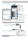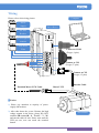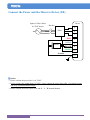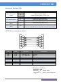
1
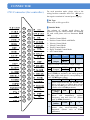
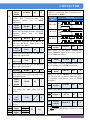
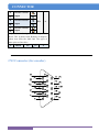
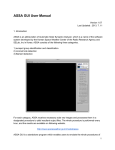
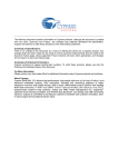
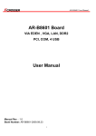
AC Servo Motor Driver
SIDC SIA series
User’s Manual
█ Thank you for purchasing 「SIDC SIA」series.
█ Please read this manual thoroughly before operating the servo system.
ver.080603E
NAMES & FUNCTION
Driver 【SIDC 650】
front
█ Displays 5 digit,
7-segment LED
█ TB (terminal button)
█ Power Supply Line
Connect AC power supply
line
█ Switch keys
QUIT cancel/exit
up
shift
down
ENTER select/input
█ Motor Connect Line
Connect the motor UVW cable
█ Communication for
RS-232(COM)
Use for hyper terminal control.
█ Connector1(CN1)
Use to connect the controller.
█ Ground
█ Connector2(CN2)
Use for encoder cable.
Motor 【SIA Series】
█ Encoder Cable
█ Motor UVW Cable
1 WIRING
Wiring
Please refer to this wiring picture:
Computer
Power
Supply
Servo Driver
No-fuse
Breaker
Electromagnetic
contacts
Line Noise
Filter
Connect to COM
(D type, 9 pins)
R
S
T
U
V
W
FG
FG
Connect to CN1
(D type,37 pins)
Connect to CN2
(D type, 15 pins)
Encoder Cable
Extended Motor UVW Cable
Motor UVW
█ Notices
1) Please pay attention to capacity of power
supply and breakers.
2) After shut down the power. Because the high
voltage contain in the driver, please DO NOT
touch the TB terminal(R、S、T and U、V、W)
and encoder cable for safe. Please wait until the
LED put out, user can touch the terminal
button.
Servo
Motor
2
WIRING
Connect the Power and the Motor to Driver (TB)
Signal or Three Phase
AC220V Power
Driver
Breaker
R
Filter
S
T
RED
U
WHITE
V
BLACK
W
GREEN
FG
Motor
Ground
FG
█ Notices
1) Please confirm the power line is AC 220V.
2) If user connect the signal-phase AC220V, please connect the power lines to R、S terminal buttons
and keep T terminal button empty.
3) Please confirm the motor cable color and U、V、W terminal buttons.
3 CONNECTOR
Terminal Button(TB)
Name
Main circuit power
supply
Servo motor power
Symbol
R
S
Description
Connect to power supply
(1-phase or three-phase AC220±15%)
T
U
V
W
Connect the red motor cable
Connect the white motor cable
Connect the black motor cable
The earth terminal of
motor
FG
Connect the green motor cable
The earth terminal of
driver
FG
Connect to the earth terminal of the servo motor and to the
protective earth (PE) of the control box to perform grounding.
COM (for communication)
NO.
Pin 1
Pin 2
Pin 3
Pin 4
Pin 5
Pin 6
Pin 7
Pin 8
Pin 9
Name
CD
TXD
RXD
DSR
GND
DTR
CTS
RTS
RI
Direction
SIDC650→PC
PC→SIDC650
Description
Transmit
Receive
Data
Ground
Data Terminal Ready
Clear To Send
Request To Send
● The setting of COM port:
Baud Rate: 9600
Data Bits: 8 Check: None
Stop Bits: 1
Flow Control: Hardware
4
CONNECTOR
CN1 Connector (for controller)
For each operation mode, please refer to the
wiring between controller and CN1. (DG pin is
the negative terminal of external power supply)
█ I/O Type
Please refer to I/O type at P.16
█ Suitable Mode
The column of suitable mode shows the
applicative rage for control method. The meaning
for each word please refer to Parameter PN01
(MD).
0:Position Control Mode
1:Position Control Mode with Buffer
2:Velocity Control Mode
3:Voltage Control Mode
4:Torque Control Mode
5:Hyper Terminal Control Mode
A:All Control Mode
I/O
Suitable
Pin
Name
Symbol
Type
Mode
+12V
1
±12 V
21
Output
-12V
Supply ±12VDC/10mA MAX output voltage.
2
Speed/Torq VCMD
AI
2,3
ue Input
20
AG
The speed and torque command can
input VCMD pin, and AG is the analog ground.
The Max torque and speed is corresponding to
±10V VCMD input voltage.
Servo off SVOFF SI
A
When open-circuit this pin and DG pin,
3 driver will servo on. When short-circuit
this pin and DG pin, driver will servo off.
(Please refer to PN04 parameter)
Emergenc
EMC
SI
A
y Stop
When short-circuit this pin and DG pin,
22
driver
will
immediately
execute
emergency stop and servo off. (Please
refer to PN04 parameter)
CW Drive
CWHC SI
A
Inhibit
When short-circuit this pin and DG pin, it
4
means
that
travel-exceeding
has
happened. (Please refer to PN05
parameter)
5 CONNECTOR
23
5
24
6
CCW
Drive
CCWHC
SI
A
Inhibit
When short-circuit this pin and DG pin, it
means
that
travel-exceeding
has
happened. (Please refer to PN05
parameter)
Home
HORG
SI
1,5
Signal
When short-circuit this pin and DG pin, it
means that mechanical home signal has
inputted. (Please refer to PN03
parameter)
Reset
RESET
SI
A
When short-circuit this pin and DG pin, it
will reset the driver. (Reset driver can
also remove the alarm.)
JOG
Forward
7
26
8
27
9
28
10
SI
1
When short-circuit this pin and DG pin,
motor will jog forward.
JOG
Backward
25
JOG+
JOG-
SI
1
When short-circuit this pin and DG pin,
motor will jog backward.
Homing
HOME
SI
1
When short-circuit this pin and DG pin
(ON→OFF), motor will rotate back to the
mechanical home.
Pulse
SI
1
Input
HALT
Inhibit
When short-circuit this pin and DG pin
(ON→OFF), the input pulses will be
invalid.
External
+24V
+24V
A
Power
User need to supply external +24V power
for I/O.
PLS+
Pulse
Input
PLSPI
0,1
DIR+
Direction
Input
DIR-
SIDC650 can accept three command types.
(Please refer to PN02):
Pin Status
Forward
Backward
Command
Type
Pulse+Dir
CW/CCW
A +
AB Phase
A B +
B -
29
11
Servo
Ready
READY
SO
A
After power on the driver without any
alarms, READY signal will be ON. (Please
refer to PN07 parameter)
30
12
Alarm
ALARM
SO
A
If any alarm occurring, ALARM signal will
be ON. (Please refer to PN07 parameter)
31
13
Holding
Break
BREAK
SO
A
When servo off, the BREAK pin will output
ON. This pin can be used to control the relay
of magnetic break.(Please refer to PN06
parameter)
32
14
In
Position
POSOK
SO
0,1
Please refer to PN18 parameter
33
15
Output 4
OUT4
SO
A
This output pin is reserved by manufactory.
Z-phase
A
PHZOUT SO
Output
16
The PHZOUT pin signal is the same as
the PZ+ signal, and the type of this pin is open
collector.
34
6
CONNECTOR
35
17
36
18
37
19
Encoder A-Phase
Output
Encoder B-Phase
Output
PO
A
Encoder Z-Phase
Output
Output the encoder signal which be inputted to
driver. The A-phase leads B-phase 90 degrees,
when view from the shaft end. The types of
these pins are line-drive.
Shield
FG
A
CN2 Connector (for encoder)
7