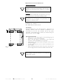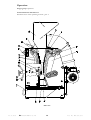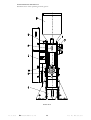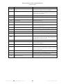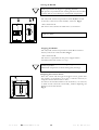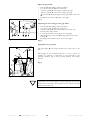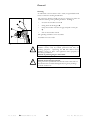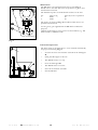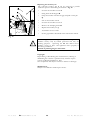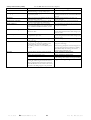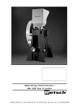
1
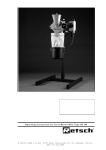
Operating Instructions BB 200 Jaw Crusher Retsch GmbH & Co. KG, Rheinische Str.36, 42781 Haan, Germany Doc. No. E98.053.9999 Information on these operating instructions The present operating instructions for the Model BB 200 jaw crusher provides all the required information on the topics mentioned in the table of contents. These guidelines are provided for the use of the groups specified in each chapter and will ensure safe operation of the BB 200, for the purpose for which it was intended. Familiarity with the pertinent chapters is a prerequisite for confident, proper utilization by the various persons who deal with the machine. The present technical manual is designed for use both as a reference work and as a learning guide. Each of the individual chapters is a self-contained unit. These operating instructions do not contain any information on repairs. If repairs should ever become necessary, kindly get in touch with your supplier or contact directly the Retsch GmbH & Co. KG. 26.10.1998 Retsch GmbH & Co. KG 2 Doc. No. E98.053.9999 Information on these operating instructions ............................. 2 Safety ....................................................................................... 4 Safety note ..................................................................................... 4 Warnings ....................................................................................... 5 Repairs .......................................................................................... 5 Confirmation.................................................................................. 5 Technical specifications ........................................................... 6 Utilization in accordance with the intended purpose............................. 6 Gap width adjustment range ............................................................. 6 Throughput rate and ultimate fineness ............................................... 6 Receiver drawer volume................................................................... 6 Noise emissions.............................................................................. 6 Electrical protection class ................................................................. 6 Rated power................................................................................... 6 Noise emissions.............................................................................. 7 Equipment dimensions (approximate) ................................................ 7 Footprint ....................................................................................... 7 Materials for the breaker jaws............................................................ 8 Materials analyses............................................................................ 8 Materials for the wearing plates ......................................................... 9 Materials analyses............................................................................ 9 Shipping and installation.......................................................... 10 Packing ......................................................................................... 10 Shipping ........................................................................................ 10 Intermediate storage........................................................................ 10 Intermediate storage........................................................................ 10 Standard equipment ........................................................................ 10 Requirements for the installation site.................................................. 11 Installation..................................................................................... 11 Electrical connection ....................................................................... 11 Operation................................................................................. 12 Control elements and their use.......................................................... 12 Schematic view of the operating controls , part 1: ..................... 12 Control elements and their use.......................................................... 13 Schematic view of the operating controls, part 2: ...................... 13 The operating controls and their functions.......................................... 14 Summary table .................................................................... 14 Starting the BB 200 ......................................................................... 15 Stopping the BB 200 ....................................................................... 15 Emptying the receiver drawer ........................................................... 15 Adjust the gap width ....................................................................... 16 Adjusting the zero setting for the gap width ........................................ 16 Fill product to be ground ................................................................. 16 Working instructions ................................................................ 17 General ......................................................................................... 17 Grain size of feedstock product ........................................................ 17 Properties of the product being ground .............................................. 17 Fill volume..................................................................................... 17 General .................................................................................... 18 Cleaning ........................................................................................ 18 Maintenance................................................................................... 19 Functional inspections ..................................................................... 19 Replacing the breaker jaws................................................................ 20 Copyright ...................................................................................... 20 Modifications ................................................................................. 20 Safety instructions (table) ................................................................. 21 Warranty Conditions ................................................................ 22 26.10.1998 Retsch GmbH & Co. KG 3 Doc. No. E98.053.9999 Safety Target group: Anyone who deals with the machine in any capacity whatsoever. The BB 200 is a modern, high-performance product manufactured by the Retsch GmbH, incorporating engineering representing the state of the art. It is entirely safe in operation, provided that the operator is familiar with the present technical manual and uses the machine for the purpose for which it was intended. Safety note You as the owner/operator must ensure that the persons entrusted with the use of the BB 200: * have read and understand all the regulations given in the section dealing with safety, * have made themselves familiar with all the operating instructions and rules for the particular target group, prior to commencing any work, * have complete, immediate and unrestricted access to the technical manuals for this machine. * New personnel shall have been familiarized with the safe and correct use of the BB 200, prior to beginning the work, by way of instruction given by a qualified person and/or on the basis of the present technical documentation. * Incorrect operation can result in personal injury and property damage. You are responsible for your own safety and for that of your employees. * Ensure that no unauthorized persons have access to the BB 200. For your own protection, have your coworkers certify in writing the fact that they have received instruction in the operation of the BB 200. A suggestion for a printed form which can be used for this purpose will be found at the end of the chapter on safety. ! 26.10.1998 Retsch GmbH & Co. KG We reject herewith any and all claims in conjunction with personal injury or property damage resulting from failure to observe the following safety instructions. 4 Doc. No. E98.053.9999 Warnings The following symbols are used to identify specific hazard potentials: Personal injury ! Property damage Repairs These operating instructions do not include any repair instructions. In the interest of your own safety, have repairs made only by the Retsch GmbH or an authorized representative (service technician). In this case, please notify the following: Local Retsch representative Your supplier The Retsch GmbH Your address for service: ____________________________ ____________________________ ____________________________ ____________________________ Confirmation I have familiarized myself with the foreword to the operating instructions and the chapter on safety. _______________________________________ Owner/operator signature _______________________________________ Service technician's signature 26.10.1998 Retsch GmbH & Co. KG 5 Doc. No. E98.053.9999 Technical specifications Machine designation: BB 200 Utilization in accordance with the intended purpose The BB 200 is suitable for reducing medium-hard to very-hard substances as well as for brittle and tough materials. The ultimate fineness can be as little as 2 mm and, depending on the material being processed, may be even less. The following is a list of some of the materials which can be ground using the BB 200: Bakelite // bauxite // concrete // dolomite // ores // feldspar // granite // graywacke // glass // limestone // gravel // coal // coke // corundum // quartz // salts // refractory clay // slag // silicates // silicon // sintered materials // cement clinker, etc. Do not make any modifications to the machine and use only RETSCH approved spares and accessories. Failure to comply will invalidate the CE declaration and guarantee. Gap width adjustment range From 0 to about 30 mm using a threaded spindle Throughput rate and ultimate fineness The performance data, through-put rate and attainable ultimate fineness are dependent on the fracturing properties and the hardness of the product being ground. These values can only be determined empirically. Receiver drawer volume approx. 5 dm3 Noise emissions Noise level at a distance of 1m: approx. 63 dB (A) when idling The noise level can rise depending on the product being processed. Electrical protection class IP54 Rated power 1500 Watt 26.10.1998 Retsch GmbH & Co. KG 6 Doc. No. E98.053.9999 Noise emissions Noise measurements according to DIN 45635-31-01-KL3 Characteristic noise values are dependent on the fracturing properties of the product beeing ground. Examples: Workplace-related emission value LpAeq = 84 dB(A) Operating conditions: Sample material: marble, grain size 40 - 80 mm Adjusted gap width: < 1 mm Final grain size: < 5 mm Filling ratio of grinding chamber: approx. 65 % or Sound power level LWA = 101 db(A) Workplace-related emission value LpAeq = 92 dB(A) Operating conditions: Sample material: marble, grain size 40 - 80 mm Adjusted gap width: < 1 mm Final grain size: < 5 mm Filling ratio of grinding chamber: approx. 65 % Equipment dimensions (approximate) Height: 1160 mm Width: Depth: 900 mm Weight: 450 mm 300 kg net Footprint 450 mm x 900 mm; no safety clearances required! 26.10.1998 Retsch GmbH & Co. KG 7 Doc. No. E98.053.9999 Materials for the breaker jaws • Manganese steel • Stainless steel • Tungsten carbide • Steel without heavy metals Materials analyses Manganese steel Hardness approx. 1080 N/mm2 Designation X 120 Mn 12 Analysis: Stainless steel Hardness approx. 780-980 N/mm2 Designation G - X 10 Cr Ni 18/8 Analysis: Tungsten carbide Material No. 1.3401 C 01.300% Si 00.500% P 00.100% S 00.040% Mn 13.000% Fe 85.060% Material No. 1.4312 C 00.120% Si 02.000% P 00.045% Mn 01.500% S 00.030% Cr 19.500% In 10.000% Fe 66.805% Hardness approx. 73 HRC Analysis: TC Co 92.000% 08.000% Steel without heavy metals Designation C 75 W Analysis: 26.10.1998 Retsch GmbH & Co. KG 8 Material No. 1.1750 C 00.820% Si 00.400% P 00.035% Mn 00.800% S 00.035% Fe 97.910% Doc. No. E98.053.9999 Materials for the wearing plates • Rust-free steel • Tungsten carbide • Steel without heavy metals Materials analyses Rust-free steel Hardness approx. 500-700 N/mm2 Designation X 5 Cr Ni 18 10 Analysis: Tungsten carbide Material No. 1.4301 Cr 19.000% S 00.030% P 00.045% Mn 02.000% Si 01.000% C 00.070% In 10.500% Fe 84.500% Hardness approx. 73 HRC Analysis: TC Co 90.000% 10.000% Steel without heavy metals Designation RSt 37-2 Analysis: Material No. 1.0038 C 00,170% P 00,045% S 00,045% N 00,009% Mn 01,400% Fe 98,331% The percentages given above in the analyses are mean values. 26.10.1998 Retsch GmbH & Co. KG 9 Doc. No. E98.053.9999 Shipping and installation Packing The type of packaging used has been selected in accordance with the shipping mode. It complies with generally accepted packaging guidelines. Please retain the packaging for the duration of the guarantee since, in case of a claim, returning in unsuitable packaging can jeopardize your guarantee entitlements. Shipping The BB 200 shall not be subjected to impact or vibration during transportation; it shall not be thrown. The electronic and mechanical components could otherwise be damaged. In order to be able to transport the BB 200 with a crane (capable of lifting at least 500 kg), it should be fixed with ties as in figure 1. Intermediate storage Please pay attention to the fact that the BB 300 must also be kept dry when in intermediate storage. Abb.1 Temperature fluctuations In case of wide temperature fluctuations (during shipment by air, for instance) the BB 200 will have to be protected against condensation; the electronic components could otherwise be damaged. Intermediate storage Also ensure that the BB 200 is stored in a dry place. Standard equipment * * * * BB 200 1 grease gun (in the receiver drawer) 1 receiver drawer (in place in the BB 200) 1 copy of the operating instructions Check to ensure that the shipment is complete and includes any accessories you have ordered separately. Verify that the BB 200 operates perfectly (see in this regard the chapter on operation). Notify the forwarder and Retsch GmbH immediately (within 24 hours) if the shipment is incomplete or damaged. Under certain circumstances compensation cannot be paid for claims which are lodged later. 26.10.1998 Retsch GmbH & Co. KG 10 Doc. No. E98.053.9999 Requirements for the installation site Ambient temperature: 5°C to 40°C When the ambient temperature exceeds or falls below that specified, the electronic and mechanical components may be damaged, and performance data changed to an unknown extent. Humidity: Maximum relative humidity 80% at temperatures up to 31°C; linear decline down to 50% relative humidity at 40°C. At higher humidity, the electronic and mechanical components may be damaged, and performance data changed to an unknown extent. Installation site – altitude max. 2000 m above mean sea level Installation Set up the BB 200 only a flat and solid surface. Anchoring is not absolutely necessary since the vibrations transmitted to the environment by the free mass moments will be only barely perceptible. The machine may, if desired, be anchored using the holes in the feet as shown in Fig.1. Electrical connection * * * * * Fig. 1 Kindly refer to the wiring diagram on the following page for information as to the type of connection. Refer to the data plate for information on the voltage and frequency at which the BB 200 is to be operated. Ensure that the values shown there correspond to those for the local power supply. Use the supplied power cord to connect the BB 200 to the power supply. When connecting the power cord to the power source, be sure that the supply circuit is fused in accordance with local codes. Failure to observe the values on the data plate can cause damage to either the electrical or the mechanical components or both. 26.10.1998 Retsch GmbH & Co. KG 11 Doc. No. E98.053.9999 Operation Target group: Operators Control elements and their use Schematic view of the operating controls , part 1: Side view 26.10.1998 Retsch GmbH & Co. KG 12 Doc. No. E98.053.9999 Control elements and their use Schematic view of the operating controls, part 2: Front view 26.10.1998 Retsch GmbH & Co. KG 13 Doc. No. E98.053.9999 The operating controls and their functions Summary table Description Element Function A ON/OFF switch and motor protection switch Starts and stops the jaw crusher drive; isolates the motor from the power supply in case of overloading B Fill hopper Provides for the feed of material; prevents unintentionally reaching into the grinding chamber; prevents ejection of the material being processed C Receiver drawer V = 5 dm3 Accepts the ground sample material D Hand barrier Prevents unintentionally reaching into the grinding chamber E Hex-head bolt Affixes the hand barrier F Two machine screws The fill hopper B can be swung to the rear once these screws have been removed. G Limit switch Disables the drive (motor) when the fill hopper B is not in its normal operating position H Clamping shim Secures the breaker jaws J on the breaker arms S and T. I Machine screw Secure the clamping shim H J Breaker jaws The size reduction components proper K Pointer Indicates at scale M the width of the gap, at a tolerance of ±1mm M Scale Indicates, in conjunction with the pointer K, the width of the gap; used to zero the gap width adjustment to accommodate for breaker jaw wear. N Lock nut Locks the threaded spindle O O Threaded spindle Increases the gap width when turned to the left, decreases when turned to the right P Screw eyes Lifting points when using lifting tackle to move the device Q Pin When the pointer K is removed and the fill hopper B swung to the rear, the pin can be pulled out and the breaker arm S removed. R Wearing plate Prevents damage to the side panels S Breaker arm, stationary The breaker jaw J is mounted here; the gap width can be modified by adjusting the threaded spindle O. T Breaker arm, moving The breaker jaw J is mounted here; executes the grinding motion required for size reduction without manual effort 26.10.1998 Retsch GmbH & Co. KG 14 Doc. No. E98.053.9999 Starting the BB 200 The BB 200 may be started only in the idling mode, i.e. without product in the hopper or grinding chamber. The presence of product before starting will cause the machine to block and can cause damage to mechanical components. The ON/OFF and motor protection switch A/A1 is located on the left, at the front of the machine, at the left. Fig.2 * Press the button I. The motor starts and the movable arm is set in motion. 0 I The grinding operation can now be started, once the feed hopper is in place. Fig. 2 Stopping the BB 200 The ON/OFF and motor protection switch A is located on the left, at the front of the machine Fig.2 * Press the button 0 The motor is separated from the power supply and the movable breaker arm comes to a stop. Stop the BB 200 only when all the grinding chamber has been cleared of product. Mechanical components could be damaged by blockage. Emptying the receiver drawer Since the volume fed through the hopper can be greater than the capacity of the drawer (V=5 dm3), it will be necessary to empty the drawer C from time to time. To achieve the maximum fill level in the drawer, it is necessary to shake it back and forth occasionally, without displacing the drawer by more than 30 mm. Fig. 3 Fig. 3 26.10.1998 Retsch GmbH & Co. KG 15 Doc. No. E98.053.9999 Adjust the gap width * * * * * Start the BB 200 (idling, without product). Loosen the lock nut N (turn to the left). Turn the spindle O to the right to reduce the gap. Turn the spindle O to the left to enlarge the gap. The pointer K shows the approximate gap width at the scale M. * Re-tighten the lock nut N (turn to the right). Fig. 4 Adjusting the zero setting for the gap width * * * Start the BB 200 (idling, without product). Loosen the lock nut N (turn to the left). Turn the spindle O to the right until you hear the two breaker arms make contact. * Loosen the machine screws U (turn to the right). * Slide the 0 mark at the scale M to align with the tip of the pointer K. * Re-tighten the machine screws (turn to the right). Fig. 4 Fig. 4 Fill product to be ground The fill hopper B can accept product up to grain sizes of 90 mm. This hopper is not intended, however, to store a reserve of product; its function is exclusively to feed material to the grinding chamber and to keep ground product from being ejected. Fig. 5 Fig. 5 If the grinding chamber W is filled more than 2/3 full, then the guide plates of the fill hopper could be damaged; the moving breaker arm would force the product into the crusher housing, behind the breaker arm. 26.10.1998 Retsch GmbH & Co. KG 16 Doc. No. E98.053.9999 Working instructions Target group: Laboratory technicians General The BB 200 is a rugged, floor-mounted unit which is used primarily for preliminary grinding in preparation for final size reduction. Its continuous operating concept also makes the BB 200 suitable for integration into fully automatic and semi-automatic processing lines. The performance data, throughput rates and ultimate fineness which can be reached will depend on the breaking properties and hardness of the product and on the gap width which is selected. Grain size of feedstock product The maximum grain size is determined by the size of the fill hopper opening and in the BB 200 is a maximum of 90 mm. Properties of the product being ground Every hard and brittle product, exhibiting a hardness of greater than 3 on the Mohs scale, can as a rule be reduced with the BB 200. Wet and oily product and that with a hardness index below 3 (Mohs scale) tend to be compressed and clump in the grinding chamber, this being due to the pressure exerted by the breaker jaws. It is for this reason that pre-grinding such material is hardly possible. Fill volume If the grinding chamber W is filled more than 2/3=800ml full, then the guide plates of the fill hopper could be damaged and the moving breaker would force the product into the crusher housing, behind the breaker arm. Fig. 6 The fill level will also influence the proportion of fine material in the product or specimen after preliminary grinding; the fuller the grinding chamber, the greater the share of fines. Fig. 6 If the grinding chamber W is filled more than 2/3=800ml full, then the fill hopper guide plates could be damaged; the moving breaker arm would force product into the crusher housing, behind the breaker arm. 26.10.1998 Retsch GmbH & Co. KG 17 Doc. No. E98.053.9999 General Cleaning An industrial vacuum cleaner and a stable, long-handled brush are best suited for cleaning the BB 200. The stationary breaker arm S can also be removed to allow for sufficient cleaning of the grinding chamber. See Fig. 7 * Unscrew the machine screws F. * Swing back the fill hopper B. * Grasp the breaker arm S at the grip and pull out the pin Q. * Lift out the breaker arm S. The grinding chamber is now accessible. Assemble in reverse order. Fig. 7 26.10.1998 ! The fill hopper may be swung back (by unscrewing the two machine screws) only by trained personnel and only for cleaning purposes. Operating the BB 200 without these machine screws in place and tightened down properly is absolutely prohibited. Hazard of pinching fingers and hands! ! Do not use running water to clean the BB 200. Hazard of fatal electrical shock. Using solvents is prohibited since the felt seals at the sides of the breaker arms could be damaged and/or grease packings could be washed out. Retsch GmbH & Co. KG 18 Doc. No. E98.053.9999 Maintenance The BB 200 is to be lubricated from time to time. Fig. 8 Kindly refer to the table below for the quantities of grease and the lubrication intervals. The lubrication points are marked with red dots on the unit. No. 1 2 Quan. in kg 0.008 0.008 Interval, hours of operation 50 50 The points not shown in Fig. 8 but indicated with arrows are permanently lubricated. CE Use the grease gun supplied with the BB 200 for lubrication purposes. Ordinary multi-purpose graese can be used as lubricant, e.g. EP 4685 by ESSO / SHELL or BP. Fig. 8 Functional inspections The limit switch at the fill hopper is to be checked semiannually for proper functioning. Fig. 9 * Unscrew the front two machine screws F at the fill hopper B. * Swing the fill hopper to the rear. * The BB 200 comes to a stop * Close the fill hopper B. * The BB 200 must not restart. * Screw in the machine screws F. * Start the BB 200. Fig. 9 26.10.1998 Retsch GmbH & Co. KG 19 Doc. No. E98.053.9999 Replacing the breaker jaws The stationary breaker arm S can be removed to provide sufficient space for dismantling the machine. Fig. 10 * Unscrew the machine screws F. * Swing back the fill hopper B. * Grasp the breaker arm S at the grip and pull out the pin Q. * Lift out the breaker arm S. * Unscrew the machine screws I. * Remove the clamping shims H. * Replace the breaker jaws J. * Assemble in reverse order. * Set the gap width as described in this instruction manual. Fig. 10 ! The fill hopper may be swung back (by unscrewing the two machine screws) only by trained personnel and only for cleaning purposes. Operating the BB 200 without these machine screws in place and tightened down properly is absolutely prohibited. Hazard of pinching fingers and hands! Copyright Reproducing or distributing this documentation, utilizing or distributing the contents is permitted only with the express consent of Retsch GmbH & Co. KG. Non-compliance will subject violators to claims for damages. Modifications Subject to modification without prior notice. 26.10.1998 Retsch GmbH & Co. KG 20 Doc. No. E98.053.9999 Safety instructions (table) Procedure Safety Not paying attention to the safety instructions can lead to damage to people and property. Please retain the packaging for the duration of the guarantee period. Packaging Transport Temperature variations Scope of delivery Environmental temperature Air humidity Electrical connection Operation Cleaning 26.10.1998 for the BB 200 taken from the chapters Action Dangers Claims for damage are excluded in whatever form. In the case of complaint your warrantee rights can be endangered if the item is returned insufficiently packaged. During transportation the BB 200 should not be Electronic and mechanical components can knocked, shaken or thrown. become damaged. With severe variations in temperature, the BB Electronic components can become damaged. 200 must be protected from condensation. In the case of the delivery being incomplete Later complaints can under certain circumstances and/or transport damage, you must inform the no longer be considered. carrier and Retsch GmbH immediately (within 24 h). Drops below 5°C Electronic and mechanical components can Rises above 40°C become damaged. Performance data change by an unknown extent. Rises above 80% Electronic and mechanical components can at temperatures up to 31% become damaged. Performance data change by an unknown extent. Mains supply does not match the values given Electronic components can become damaged. on the type plate. During starting, stopping and disconnection, Mechanical components can possibly become there must be no material for grinding in the damaged via a blockage. crushing chamber or in the feed hopper. The crushing chamber is not be filled by more Otherwise the guide plates of the feed hopper can than 2/3. becoming damaged and the material for grinding will be delivered by the breaking arm into the crusher housing behind the arm. Each time before cleaning, pull out the mains Danger of death by electrocution. plug. Do not clean with running water. Danger of death by electrocution. Solvents are not permitted. Since they would damage the felt seals on the side of the breaking arms or wash out the grease filling. The filling hopper may be swung back for Danger of crushing for fingers and hands. cleaning, by unscrewing the two socket screws, only by assigned, trained personnel. Operation of the BB 200 without screwed-in socket screws and without the filling hopper is not permitted. Retsch GmbH & Co. KG 21 Doc. No. E98.053.9999 Warranty Conditions 1. If legitimate claims are made we shall remedy the defect or replace the goods free of charge. The purchaser shall only have a right to rescind the contract or reduce the purchase price if we have decided that it is not possible to remedy the defect and a replacement delivery cannot be made or the time limit therefore cannot be complied with or if a reasonable additional time limit of six weeks granted by the customer has not been complied with due to our fault. If the remedy or replacement delivery in fact fails the customer shall have the right to reduce the price or rescind the contract at his discretion. Further claims, in particular for damages in relation to damage not caused to the goods themselves, such as lost production, are excluded in so far as we have not acted wilfully or negligently. For goods produced by third parties we pass on the liability of the manufacturer. 2. We shall bear the costs directly incurred through the remedying of defects or the replacement delivery on the condition that claim is found to be legitimite. This also applies to the freight costs as well as the reasonable costs of removal and installation. The customer, however, undertakes to bear the reasonable costs of providing his own technicians and assistants on site. If our customer carries on business overseas, however, we shall be entitled to pay the costs, in particular costs of transport, tolls, wages and materials, ex German border. 3. Our warranty period is generally six months. We do not give any warranty on parts subject to wear. We give a warranty of two years as from purchase date when the warranty card is fully completed and returned to us within two weeks after purchase of the machines, but we do not give any warranty on parts subject to wear. The warranty period counts as from return of the warranty card. In case of initiation of the machine at a later date as of initiation, which has to be indicated on the card. The machine should be put into operation no later than 6 months after purchase date. This warranty is based on single-shift laboratory operation. For multiple-shift operations or other environments the warranty period will be respectively shorter. 4. We warrant that our goods are free from manufacturing defects. The suitability, classification and function of our goods are determined exclusively on the basis of the performance descriptions contained in the order confimation even if these differ from the order. In the latter event the customer may, within two weeks after receipt of the order confirmation, draw any possible difference from the order to our attention and come to an agreement on these with us. If the customer does not object to the specifications in the order confirmation then these shall be deemed to have been accepted. Unless an agreement to the contrary has been reached, we shall not be held liable for the suitability of the goods delivered for the use to which the customer intends to put them. The same applies to performance figures expected by the customer unless we have been able to carry out appropriate preliminary practical experiments and have, in our order confirmation, declared in writing that these performance figures shall be binding. 5. Our warranty shall also become invalid if persons other than those employed by us carry out repairs or in any other way interfere with or make alterations to the goods delivered by us or do not use suitable parts to the extent that the defect is causally connected thereto. In addition , it is a condition of our warranty that our directions for use and operation be followed. 6. If, without a release having first been obtained from us, the goods are installed in and /or connected to, attached to or incorporated in other systems or production plants then our guarantee is limited exclusively to the parts delivered by us. 7. The remedying of defects or replacement of defective parts shall, at our discretion, be carried out on site or at the seat of our company. If the repair is carried out on site, the customer shall ensure that our employee has access, unlimited in either time or space, to the purchased item. In addition, the customer may only demand that work necessary in order to fulfil warranty obligations be carried out during the normal local business hours. If such work is carried out outside our normal business hours on request, the customer shall bear the additional costs. If he wishes to have other particular work performed which goes beyond the work warranted then these costs shall be payable at the actual valid price. 26.10.1998 Retsch GmbH & Co. KG 22 Doc. No. E98.053.9999