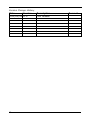
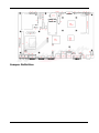
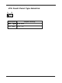
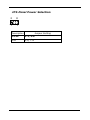
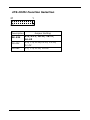
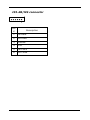
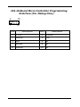
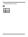
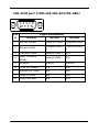
1
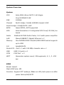
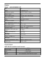
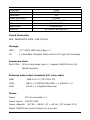
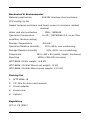
WTP-8866-19 User’s Manual PN: 205G00WTP88660 V1.0 Copyright 2012, ALL RIGHTS RESERVED. Greeting & Setup Thank you for purchasing the WTP-8866-19 Panel PC. We wish that this unit will be durable and reliable in providing your needs. Please follow the instructions below to ensure the unit continues to have high performance Unpacking After opening the carton, there will be a unit with an accessory box. Examine the contents to see if there are damages to the unit and if all accessories are present. Setting up Please read this manual carefully and remember to keep this manual for future reference. Safety Instructions & Cleaning The unit has undergone various tests in order to comply with safety standards. Inappropriate use may be dangerous. Please remember to follow the instructions below to insure your safety during the installation and operating process. Transporting & Placement of unit 1. When moving the unit on a cart; be very cautious. Quick stops, excessive forces and uneven surfaces may cause the cart to overturn thus risking the unit to fall to the ground. 2. If the Monitor display unit does fall to the ground, immediately turn the power off and disconnect cords. Then contact a service technician for repairs. Continual use of the unit may result II cause a fire or electric shock. Also, do not repair the unit on your own. 3. Before suspending the unit, make sure the material used for suspension is sturdy and stable. If not properly suspended, the display unit may fall and cause serious injury to people standing nearby as well as to the unit itself. 4. If you wish to mount the display unit, remember to use only the mounting hardware recommended by the manufacturer. Electrical and Power Source Related 1. This Monitor display unit must operate on a power source as shown on the specification label. If you are not sure what type of power supply used in the area, consult your dealer or local power supplier. 2. The power cords must not be damaged. Applied pressure, added heat, and tugging may damage the power cord. 3. The power cord must be routed properly when setup takes place. We advise that this aspect measure is to prevent people from stepping on the cords or while the unit is suspended to prevent flying objects from getting tangled with the unit. 4. Do not overload the AC outlets or extension cords. Electrical shocks or fires may occur from overloading. 5. Do not touch the power source during a thunderstorm. 6. If your hands are wet, do not touch the plug. 7. Use your thumb and index finger, grip firmly on the power cord to disconnect from the electrical socket. By pulling the power cord, may result in damaging it. 8. If the unit is not going to be in use for an extended period of III time, remember to disconnect the unit. 9. Connect the unit to a power source with the same numerical value as spec. label shown. Please use only the power cord provided by the dealer to ensure safety and EMC compliance. Various Factors of Environment 1. Having liquids seep in or inserting objects into the unit may result in electric shocks from taking and/or short circuiting the internal parts. 2. Do not place unit near heat generating sources. 3. Do not place the unit in a location where it will come in contact with fumes or steam. 4. If water has flow in or seep in, immediately disconnect power. Then contact a service technician for repairs. Servicing, Repairing, Maintenance & Safety Checks 1. If the unit is not functioning properly, observe the performance level of the display closely to determine what type of servicing is needed. 2. Do not attempt to repair the unit on your own. Disassembling the cover exposes users’ to high voltages and other dangerous conditions. Notify and request a qualified service technician for servicing the unit. 3. If any of the following situations occur turn the power source off and unplug the unit. Then contact a qualified service technician (a) The unit is soaked with liquids. (b) The unit is dropped or damaged. (c) If smoke or strange odor is flowing out of the unit. IV (d) If the power cord or plug is damaged. (e) When the functions of the unit are dysfunctional. 4. When part replacement is needed. Make sure service technician uses replacement parts specified by the manufacturer, or those with the same characteristics and performance as the original parts. If unauthorized parts are used it may result in starting a fire, electrical shock and/or other dangers. Battery Installation Follow below instructions and notice the caution for replacing and disposing of the RTC Lithium battery CR2032 for safety consideration. CAUTION: There is danger of explosion, if battery is incorrectly replaced. Replace only with the same or equivalent type recommended by the manufacturer. Dispose of used batteries according to the manufacturer’s instruction. The specification is subject to change without notice. V Version Change History Date Version 2012/03/18 V1.0 VI Description First release Remark Table of Contents System Overview .............................................................................. 10 System View ................................................................................................... 15 Setting up the System ..................................................................................... 16 Installing the Drivers .................................................................................... 19 BIOS Setup Information ................................................................. 20 Appendix........................................................................................... 47 A. Jumper Setting and Connectors List .......................................... 47 JP1-Touch Panel Wire Selection ........................................................ 49 JP2-Touch Panel Type Selection ....................................................... 50 JP3-Panel Power Selection .................................................................. 51 JP4-Clear CMOS ...................................................................................... 52 JP5-COM1 Function Selection ............................................................ 53 J1-Touch Panel Interface ..................................................................... 54 J2-Light Sensor Connector .................................................................. 55 J3-Motion Detection Interface ........................................................... 56 J4-UI LED ................................................................................................... 57 J5-AUX FAN Connector ......................................................................... 58 J6-Panel Inverter Connector............................................................... 59 J7-GPIO Interface ................................................................................... 60 J8/J500-External LVDS Interface ..................................................... 61 J9-CPU FAN Connector ......................................................................... 62 J10-Touch Panel Controller FW Update Interface ...................... 63 J11,J13-SATA Connector ..................................................................... 64 J14-Internal LVDS Interface(18-bit Only) ..................................... 65 J15-Standard Express Card/54 Interface ...................................... 67 J16-Standard DDR2 SO-DIMM Interface ....................................... 68 J17-Standard Mini PCI Express Socket .......................................... 69 VII J18-Internal USB Connector ............................................................... 70 J20-System FAN Connector ................................................................ 71 J21-LPT Port Connector ........................................................................ 72 J22-PCI Slot Interface........................................................................... 73 J23-Debug Port (For debug only) ..................................................... 74 J24-Front Bezel Button Connector ................................................... 75 J25-Standard Compact Flash(IDE) Connector(Bootable) ........ 76 J26-Power/HDD Indicators .................................................................. 77 J27/J38-Passive Speaker Connector ............................................... 78 J28-Internal Microphone Connector ................................................ 79 J29-Internal DVI Connector ................................................................ 80 J30-Heater1 Connector ........................................................................ 81 J31-Ethernet Port 1 ................................................................................ 82 J32-Internal COM 4 (RS-232) ............................................................ 83 J33-KB/MS connector ............................................................................ 84 J34-OnBoard Micro Controller Programming Interface (For Debug Only).............................................................................................. 85 J35,J36-USB Connector ........................................................................ 86 J37-Heater2 Connector ........................................................................ 87 J39-Power Button Connector.............................................................. 88 J40-USB + Ethernet Port 2 ................................................................. 89 J41-Standard CRT Connector ............................................................. 90 J42-Reset Button .................................................................................... 91 J43-Audio Line In .................................................................................... 92 J44-Audio Microphone In ..................................................................... 93 J45-Audio Line Out ................................................................................. 94 J46-COM port 1(RS-232/RS-422/RS-485).................................... 95 J47-COM port 2(RS-232) ..................................................................... 96 VIII J48-COM port 3(RS-232) ..................................................................... 97 PJ1-HDD Power Connector .................................................................. 98 PJ2-Power Jack Connector .................................................................. 99 B. Wake UP on LAN Function ........................................................ 99 IX System Overview System CPU Intel /BGA /Atom N270 1.6G Single Core/533MHZ/2.5W FSB 533MHz Chipset North bridge: Intel® 945GSE chipset 4.5W South bridge: Intel® CH7M 1.5W BIOS Award BIOS, ACPI supported VGA Intel Generation 3.5 integrated GFX Core(133 MHz) on board Audio Realtek ALC286 Audio Codec, 2+2 watts power amplifier LAN Marvell 88E8071 Gigabit Ethernet x 2 Memory One 200PIN DDR2 533/667/800 DIMM socket supports up to 2GB I/O Intel® ICH7M Serial ATA Port x 1 with 150 MB/s transfer rate x 1 USB USB 2.0 ports x 4 COM COM Port x 3 WDT Generates system reset; 256 segments, 0, 1, 2…255 sec. BIOS Brand: Award Flash ROM size: 8M Function Support RTC wakeup /Wake on LAN /auto power on after power failure/PnP/ACPI 10 Display Panel AUO G190EG01 V0 Size 19" Model G190EG01 V0 Resolution (pixel) SXGA (1280 x 1024) Aspect Ratio 5:4 Active Area (mm) 376.32 (H) x 301.06(V) Pixel Pitch (mm) 0.294 Mode Normally White Number of Colors 16.7M Color Saturation (NTSC %) 72 View Angle (H/V) 170 / 160 Brightness (cd/m²) 450 (Typ. Center point) Contrast Ratio Response Time (ms) (at 25°C) Power Consumption (W)(typ) Interface 1000 : 1 (Typ) Supply Voltage (V) 5 Backlight CCFL Outline Dimensions (mm) 396.0 x 324.0 x 18.5 Weight (g) 2400 (Typ) 5 (Typ) 26.71 W 2ch LVDS Touch Screen AMT 28115 resistive touch screen Model name Type Glove Stylus 11 AMT AD-2511 5 wire RES Any type glove No Limitation, can use any stylus Interface Light Transmission Hardness Glass thickness Linearity Active area Resolution Lifetime USB 80± 3% 3H 1.8mm X≦1.5%, Y≦1.5% 212x159.20 4096x4096 36 million activations Touch Controller RES PENMOUNT 6300, USB TOUCH Storage HDD CF 2.5” SATA HDD drive bay x 1 1 x bootable Compact Flash slot for CF type I/II storages Expansion slots Mini-PCIe 52 pin card-edge type x 1 support half/full size (for WLAN module) External water/dust resistant I/O (rear side) USB USB 2.0 x 2 (TS-1210-15) COM DB-9 x 2 (RS232/422/485 x 1, RS232 x 1) LAN RJ-45 x 1 (Gigabit Ethernet) Power Power DC-In connector x 1 Power Input DC12V~28V Power Adapter AC 90 ~ 264V / 47 ~ 63 Hz / DC output 12V, Power ON/Off and reset buttons at rear side 12 Mechanical & Environmental Material construction SUS304 stainless steel enclosure CPU cooling by fan Gasket between enclosure and touch screen to minimize residual material Water and dust protection IP66 / NEMA4X Operation Temperature 0~40℃ (IEC60068-2-2, no air flow condition, fanless cooling) Storage Temperature -20~60℃ Operation Relative Humidity 10%~90%, non-condensing Storage Relative Humidity Dimensions Mounting WTP-8866-19 Net weight 10%~90%, non-condensing 395 x 345 x 65 (width, height, thickness) VESA (100x100 mmxmm) 8.8 KG WTP-8866-19+Wall Mount net weight: 12 KG WTP-8866-19+Wall Mount gross weight: 13.5 KG Packing list 1. WTP-8866-19 2. CD-Title for driver and manual 3. Power adapter 4. Power cord 5. Options Regulatory FCC-A, CE (EMC) 13 14 System View 15 Setting up the System The following is a summary of the steps in setting up the system for use. CAUTION: Make sure that power to the system and each of the devices to be connected is switched OFF before plugging in the connectors. 1. Make any required external connections such as the keyboard, and mouse. 2. Plug the appropriate end of the power cord into the power connector of the system. Then plug the other end of the power cord to an electrical outlet. 3. Press the power switch of the system to turn on the system’s power. 4. If necessary, run the BIOS SETUP program to configure the system (see Chapter 3). 5. Install the software drivers if necessary. 16 Installing System Software Recent releases of operating systems from major vendors include setup programs, which load automatically and guide you through hard disk preparation and operating system installation. The guidelines below will help you determine the steps necessary to install your operating system on the Panel PC hard drive. NOTE: Some distributors and system integrators may have already pre-installed system software prior to shipment of your Panel PC. Installing software requires an installed HDD. Software can be loaded in the WTP-8866-19 Panel PC using any of below methods: Method 1: Use the Ethernet You can use the Ethernet port to download software from the net to the HDD that has been pre-installed in WTP-8866-19 Panel PC Method 2: Use the COM Port By connecting another PC to the WTP-8866-19 Panel PC with an appropriate cable, you can use transmission software to transmit Operation System Software to the HDD that has been pre-installed in the WTP-8866-19 Panel PC. Method 3: Use a External CD-ROM In order to boot up system from USB-CD/DVD drive, please connect USB-CD/DVD drive, turn on computer power, keep on pressing “F11” key, go into BIOS quick boot menu, select “USB-CD ROM”, WAIT FOR 20 SECONDS, then press enter, system OS will boot up from USB-CD/DVD drive directly 17 Then you can use the external CD-ROM to transmit the software to the HDD that has been pre-installed in the WTP-8866-19 Panel PC 18 Installing the Drivers After installing your system software, you will be able to set up the LAN, VGA, Audio and USB functions. All drivers are stored in a CD disc, which can be found in your accessory pack. The various drivers and utilities in the disc have their own text files that help users install the drivers and understand their functions. 19 BIOS Setup Information BIOS Introduction The Award BIOS (Basic Input/Output System) installed in your computer system’s ROM supports Intel processors. The BIOS provides critical low-level support for a standard device such as disk drives, serial ports and parallel ports. It also adds virus and password protection as well as special support for detailed fine-tuning of the chipset controlling the entire system. BIOS Set up The Award BIOS provides a Setup utility program for specifying the system configurations and settings. The BIOS ROM of the system stores the Setup utility. When you turn on the computer, the Award BIOS is immediately activated. Pressing the <Del> key immediately allows you to enter the Setup utility. If you are a little bit late pressing the <Del> key, POST (Power On Self Test) will continue with its test routines, thus preventing you from invoking the Setup. If you still wish to enter Setup, restart the system by pressing the ”Reset” button or simultaneously pressing the <Ctrl>, <Alt> and <Delete> keys. You can also restart by turning the system Off and back On again. The following message will appear on the screen: Press <DEL> to Enter Setup In general, you press the arrow keys to highlight items, <Enter> to 20 select, the <PgUp> and <PgDn> keys to change entries, <F1> for help and <Esc> to quit. When you enter the Setup utility, the Main Menu screen will appear on the screen. The Main Menu allows you to select from various setup functions and exit choices. Phoenix - Award BIOS CMOS Setup Utility The section below the setup items of the Main Menu displays the control keys for this menu. At the bottom of the Main Menu just below the control keys section, there is another section, which displays information on the currently highlighted item in the list. 21 Note: If the system cannot boot after making and saving system changes with Setup, the Award BIOS supports an override to the CMOS settings that resets your system to its default. Warning: It is strongly recommended that you avoid making any changes to the chipset defaults. These defaults have been carefully chosen by both Award and your system manufacturer to provide the absolute maximum performance and reliability. Changing the defaults could cause the system to become unstable and crash in some cases. Standard CMOS Features “Standard CMOS Features” choice allows you to record some basic hardware configurations in your computer system and set the system clock and error handling. If the motherboard is already installed in a working system, you will not need to select this option. You will need to run the Standard CMOS option, however, if you change your system hardware configurations, the onboard battery fails, or the configuration stored in the CMOS memory was lost or damaged. Phoenix - Award BIOS CMOS Setup Utility Standard CMOS Features 22 At the bottom of the menu are the control keys for use on this menu. If you need any help in each item field, you can press the <F1> key. It will display the relevant information to help you. The memory display at the lower right-hand side of the menu is read-only. It will adjust automatically according to the memory changed. The following describes each item of this menu. Date The date format is: Day : Sun to Sat Month : 1 to 12 Date : 1 to 31 Year : 1999 to 2099 To set the date, highlight the “Date” field and use the PageUp/ PageDown or +/- keys to set the current time. 23 Time The time format is: Hour : 00 to 23 Minute : 00 to 59 Second : 00 to 59 To set the time, highlight the “Time” field and use the <PgUp>/ <PgDn> or +/- keys to set the current time. IDE Channel Master/Slave The onboard Serial ATA connectors provide Primary and Secondary channels for connecting up to four Serial ATA hard disks. Each channel can support up to two hard disks; the first is the “Master” and the second is the “Slave”. Press <Enter> to configure the hard disk. The selections include Auto, Manual, and None. Select ‘Manual’ to define the drive information manually. You will be asked to enter the following items. Capacity: Capacity/size of the hard disk drive Cylinder: Number of cylinders Head: Number of read/write heads Pre comp: Write pre compensation Landing Zone: Sector: Landing zone Number of sectors The Access Mode selections are as follows: Large Auto 24 (for MS-DOS only) Remarks: The main board supports 4 serial ATA ports and are represented in this setting as IDE Channel 2. Video This field selects the type of video display card installed in your system. You can choose the following video display cards: EGA/VGA For EGA, VGA, SEGA, SVGA or PGA monitor adapters. (default) CGA 40 Power up in 40 column mode. CGA 80 Power up in 80 column mode. MONO For Hercules or MDA adapters. Halt On This field determines whether or not the system will halt if an error is detected during power up. All errors No errors All,But Keyboard 25 Whenever the BIOS detect a non-fatal error, the system will stop and you will be prompted. The system boot will not be halted for any error that may be detected. The system boot will not be halted for a keyboard error; it will stop for all other errors Advanced BIOS Features This section allows you to configure and improve your system and allows you to set up some system features according to your preference. Phoenix - Award BIOS CMOS Setup Utility Advanced BIOS Features CPU Feature Press Enter to configure the settings relevant to CPU Feature. Hard Disk Boot Priority 26 With the field, there is the option to choose, aside from the hard disks connected, “Bootable add-in Cards” which refers to other external devices. Virus Warning If this option is enabled, an alarm message will be displayed when trying to write on the boot sector or on the partition table on the disk, which is typical of the virus. CPU L1 and L2 Cache Cache memory is additional memory that is much faster than conventional DRAM (system memory). CPUs from 486-type on up contain internal cache memory, and most, but not all, modern PCs have additional (external) cache memory. When the CPU requests data, the system transfers the requested data from the main DRAM into cache memory, for even faster access by the CPU. These items allow you to enable (speed up memory access) or disable the cache function. By default, these items are Enabled. CPU L3 Cache Enabled or Disabled Quick Power On Self Test When enabled, this field speeds up the Power On Self Test (POST) after the system is turned on. If it is set to Enabled, BIOS will skip some items. 27 First/Second/Third Boot Device These fields determine the drive that the system searches first for an operating system. The options available include Hard Disk, CDROM,USB-FDD, USB-ZIP, USB-CDROM ,and Disabled. Boot Other Device These fields allow the system to search for an OS from other devices other than the ones selected in the First/Second/Third Boot Device. Boot Up NumLock Status This allows you to activate the NumLock function after you power up the system. Gate A20 Option This field allows you to select how Gate A20 is worked. Gate A20 is a device used to address memory above 1 MB. Typematic Rate Setting When disabled, continually holding down a key on your keyboard will generate only one instance. When enabled, you can set the two typematic controls listed next. By default, this field is set to Disabled. Typematic Rate (Chars/Sec) When the typematic rate is enabled, the system registers repeated keystrokes speeds. Settings are from 6 to 30 characters per 28 second. Typematic Delay (Msec) When the typematic rate is enabled, this item allows you to set the time interval for displaying the first and second characters. By default, this item is set to 250msec. Security Option This field allows you to limit access to the System and Setup. The default value is Setup. When you select System, the system prompts for the User Password every time you boot up. When you select Setup, the system always boots up and prompts for the Supervisor Password only when the Setup utility is called up. APIC Mode APIC stands for Advanced Programmable Interrupt Controller. The default setting is Enabled. MPS Version Control for OS This option is specifies the MPS (Multiprocessor Specification) version for your operating system. MPS version 1.4 added extended configuration tables to improve support for multiple PCI bus configurations and improve future expandability. The default setting is 1.4. OS Select for DRAM > 64MB This option allows the system to access greater than 64MB of DRAM 29 memory when used with OS/2 that depends on certain BIOS calls to access memory. The default setting is Non-OS/2. Report No FDD For WIN 95 If you are using Windows 95/98 without a floppy disk drive, select YES/NO to release IRQ6. This is required to pass Windows 95/98's SCT test. You should also disable the Onboard FDC Controller in the Integrated Peripherals screen when there's no floppy drive in the system. If you set this feature to Disabled, the BIOS will not report the missing floppy drive to Win95/98. Full Screen LOGO Show The logo appears at the right side of the monitor screen when the system is boot up. The default setting is Disabled. Small Logo (EPA) Show The EPA logo appears at the right side of the monitor screen when the system is boot up. The default setting is Disabled. 30 Advanced Chipset Features This Setup menu controls the configuration of the chipset. Phoenix - Award BIOS CMOS Setup Utility Advanced Chipset Features DRAM Ting Selectable The logo appears at the right side of the monitor screen when the system is boot up. The default setting is [By SPD]. SLP_S4# Assertion Width [4 to 5 Sec.] System BIOS Cacheable The setting of Enabled allows caching of the system BIOS ROM at F000h-FFFFFh, resulting in better system performance. However, if any program writes to this memory area, a system error may 31 result. Memory Hole At 15M-16M In order to improve performance, certain space in memory can be reserved for ISA cards. This memory must be mapped into the memory space below 16 MB. The choices are Enabled and Disabled. PCI Express Root Port Func By Default. VGA Setting The fields under the VGA Setting and their default settings are: PEG/On Chip VGA Control: Onchip VGA On-Chip Frame Buffer Size: [8MB] DVMT Mode: [DVMT] DVMT/Fixed Memory Size: [128MB] Boot Display: [CRT+LFP] Panel Scaling: [Auto] 32 Integrated Peripherals This section sets configurations for your hard disk and other integrated peripherals. Phoenix - AwardBIOS CMOS Setup Utility Integrated Peripherals OnChip IDE Device IDE HDD Block Mode This field allows your hard disk controller to use the fast block mode to transfer data to and from your hard disk drive. IDE DMA transfer access This field allows your hard disk controller to use the fast block mode to transfer data to and from your hard disk drive. 33 IDE Primary/Secondary Master/Slave PIO These fields allow your system hard disk controller to work faster. Rather than have the BIOS issue a series of commands that transfer to or from the disk drive, PIO (Programmed Input/Output) allows the BIOS to communicate with the controller and CPU directly. The system supports five modes, numbered from 0 (default) to 4, which primarily differ in timing. When Auto is selected, the BIOS will select the best available mode. IDE Primary/Secondary Master/Slave UDMA These fields allow your system to improve disk I/O throughput to 33Mb/sec with the Ultra DMA/33 feature. The options are Auto and Disabled. OnChip Secondary PCI IDE This field, by default, is enabled Onboard Device Press Enter . This field, by default, is [Auto] Super IO Device 34 KBC input clock Default is [12 MHz] Power ON Function This field is related to how the system is powered on – such as with the use of conventional power button, keyboard or hot keys. The default is BUTTON ONLY. Onboard Serial Port These fields allow you to select the onboard serial ports and their addresses. The default values for these ports are: Serial Port 1 [3F8/IRQ4] Serial Port 2 [2F8/IRQ3] UART Mode Select This field determines the UART 2 mode in your computer. The default value is Normal. Other options include IrDA and ASKIR. Onboard Parallel Port These fields allow you to select the onboard parallel ports and their addresses. Parallel Port Mode[SPP/EPP/ECP/ECP+EPP/Normal] Default is [SPP] These fields allow you to select the onboard parallel ports and set their modes. 35 PWRON After RWR-Fail Default is [Off] This field sets the system power status whether on or off when power returns to the system from a power failure situation. USB Device Setting USB 1.0 Controller The options for this field are Enabled and Disabled. By default, this field is set to Enabled. USB 2.0 Controller The options for this field are Enabled and Disabled. By default, this field is set to Enabled. In order to use USB 2.0, necessary OS drivers must be installed first. Please update your system to Windows 2000 SP4 or Windows XP SP2. USB Operation Mode The options for this field are Full/Low speed and High speed. By default, this field is set to High speed. USB Keyboard Function The options for this field are Enabled and Disabled. By default, this field is set to Enabled. 36 USB Mouse Function The options for this field are Enabled and Disabled. By default, this field is set to Enabled. USB Storage Function The options for this field are Enabled and Disabled. By default, this field is set to Enabled. Power Management Setup Phoenix – Award BIOS CMOS Setup Utility Power Management Setup ACPI Function Enable this function to support ACPI (Advance Configuration and 37 Power Interface). ACPI Suspend Type The default setting of the ACPI Suspend mode is S3(STR). RUN VGABIOS if S3 Resume The default setting of this field is Auto. Power Management This field allows you to select the type of power saving management modes. There are three selections for Power Management. User Define Each of the ranges is from 1 min. to 1hr. Except for HDD Power Down which ranges from 1 min. to 15 min. Minimum power management Maximum power management. Min.Saving Max.Saving Video Off Method This field defines the Video Off features. There are three options. Blank Screen Writes blanks to the video buffer. V/H SYNC + Blank Blank the screen and turn off vertical and horizontal scanning. DPMS Default setting, allows BIOS to control the video display. Video Off In Suspend 38 When enabled, the video is off in suspend mode. The default setting is Yes. Suspend Type The default setting for the Suspend Type field is Stop Grant. Modem Use IRQ This field sets the IRQ used by the Modem. By default, the setting is 3. Suspend Mode When enabled, and after the set time of system inactivity, all devices except the CPU will be shut off. By default, the setting is Disabled. HDD Power Down When enabled, and after the set time of system inactivity, the hard disk drive will be powered down while all other devices remain active. Soft-Off by PWR-BTTN This field defines the power-off mode when using an ATX power supply. The Instant Off mode allows powering off immediately upon pressing the power button. In the Delay 4 Sec mode, the system powers off when the power button is pressed for more than four seconds or enters the suspend mode when pressed for less than 4 seconds. 39 Wake-Up by PCI card This field enables or disables the power on of the system through the LAN. Power on by Ring By default, this field is disabled. USB KB Wake-Up From S3 By default, this field is disabled. Resume by Alarm This field enables or disables the resumption of the system operation. When enabled, the user is allowed to set the Date and Time. Disabled Enabled Date(of Month) Alarm: Set power on date The default Everyday is 0,it means Time(hh:mm:ss) Alarm Set power on time **Reload Global Timer Events** The HDD, FDD, COM, LPT Ports, and PCI PIRQ are I/O events that can prevent the system from entering a power saving mode or can awaken the system from such a mode. When an I/O device wants to gain the attention of the operating system, it signals this by causing an IRQ to occur. When the operating system is ready to 40 respond to the request, it interrupts itself and performs the service. Primary IDE 0 [Disabled] Primary IDE 1 [Disabled] Secondary IDE 0 [Disabled] Secondary IDE 1 [Disabled] FDD’COM’ LPT port [Disabled] PCI PIRQ[A-D]# 41 [Disabled] PNP/PCI Configurations This option configures the PCI bus system. All PCI bus systems on the system use INT#, thus all installed PCI cards must be set to this value. Phoenix - AwardBIOS CMOS Setup Utility PnP/PCI Configurations Init Display First The default setting is Onboard Reset Configuration Data This field allows you to determine whether to reset configuration data or not. The default value is Disabled. 42 the Resources Controlled by [Auto(ESCD)] This PnP BIOS can configure all of the boot and compatible devices with the use of a PnP operating system. PCI/VGA Palette Snoop Some non-standard VGA display cards may not show colors properly. This field allows you to set whether or not MPEG ISA/VESA VGA cards can work with PCI/VGA. When this field is enabled, a PCI/VGA can work with an MPEG ISA/VESA VGA card. When this field is disabled, a PCI/VGA cannot work with an MPEG ISA/VESA card. Maximum Payload Size The default setting of the PCI Express Maximum Payload Size is 4096. 43 PC Health Status This section shows the parameters in determining the PC Health Status. These parameters include temperatures, fan speeds and voltages. Phoenix - AwardBIOS CMOS Setup Utility PC Health Status Load Fail-Safe Defaults This option allows you to load the troubleshooting default values permanently stored in the BIOS ROM. These default settings are non-optimal and disable all high-performance features. 44 Load Optimized Defaults This option allows you to load the default values to your system configuration. These default settings are optimal and enable all high performance features. Set Supervisor/User Password These two options set the system password. Supervisor Password sets a password that will be used to protect the system and Setup utility. User Password sets a password that will be used exclusively on the system. To specify a password, highlight the type you want and press <Enter>. The Enter Password: message prompts on the screen. Type the password, up to eight characters in length, and press <Enter>. The system confirms your password by asking you to type it again. After setting a password, the screen automatically returns to the main screen. To disable a password, just press the <Enter> key when you are prompted to enter the password. A message will confirm the password to be disabled. Once the password is disabled, the system will boot and you can enter Setup freely. Save & Exit Setup This option allows you to determine whether or not to accept the modifications. If you type “Y”, you will quit the setup utility and save all changes into the CMOS memory. If you type “N”, you will return to Setup utility. 45 Exit Without Saving Select this option to exit the Setup utility without saving the changes you have made in this session. Typing “Y” will quit the Setup utility without saving the modifications. Typing “N” will return you to Setup utility. 46 Appendix A. Jumper Setting and Connectors List This appendix gives the definitions and shows the positions of jumpers, headers and connectors. All of the configuration jumpers on WTP-8866-19 Panel PC are in the proper position. The default settings shipped from factory are marked with (default). Note: Some of jumpers or connectors will be removed base on system configuration. Jumpers Location and list In general, jumpers on the single board computer are used to select options for certain features. To select any option, cover the jumper cap over (SHORT) or remove (NC) it from the jumper pins according to the following instructions. Here NC stands for “Not Connect”. 47 Jumper Definition 48 JP1-Touch Panel Wire Selection 2 10 1 9 Description 49 Jumper Setting 4-Wire 1-2, 3-4, 5-6, 7-8, 9-10 5-Wire 3-4, 5-6, 7-8, 9-10 8-Wire 1-2 JP2-Touch Panel Type Selection 2 8 1 7 Description Jumper Setting AMT Type 1-2, 3-4 ELO Type 50 5-6, 7-8 JP3-Panel Power Selection 2 8 1 7 Description 51 Jumper Setting +3.3V 1-2, 3-4 +5V 5-6, 7-8 JP4-Clear CMOS 1 3 Jumper Setting Description Normal 1-2 CMOS Cleared 2-3 52 JP5-COM1 Function Selection 21 1 22 2 Description 53 Jumper Setting RS-232 5-6, 9-11, 10-12, 15-17, 16-18 RS-422 3-4, 7-9, 8-10,13-15, 14-16, 21-22 RS-485 1-2, 7-9, 8-10, 19-20 J1-Touch Panel Interface 1 9 Signal Description Pin # 54 8-wire 4-wire 5-wire 1 UL(X+) UL(X+) UL(X+) 2 UR(Y+) UR(Y+) UR(Y+) 3 N/A N/A PRCBE 4 LR(X-) LR(X-) LR(X-) 5 LL(Y-) LL(Y-) LL(Y-) 6 X+_DRIVE N/A N/A 7 Y+_DRIVE N/A N/A 8 X-_DRIVE N/A N/A 9 Y-_DRIVE N/A N/A J2-Light Sensor Connector 1 Pin # 55 Description 1 Light Sense 2 NC 3 +3.3V J3-Motion Detection Interface 1 Pin # 56 Description 1 +3.3V 2 +5V 3 Motion detection 4 Ground J4-UI LED 1 Pin # 57 Description 1 +3.3V 2 Heater ON LED# 3 Key Lock LED# 4 Touch Panel Lock LED# J5-AUX FAN Connector 1 Pin # 58 Description 1 RPM 2 VCC(6~12V) 3 Ground J6-Panel Inverter Connector 1 Pin # 59 Description 1 +12V 2 +12V 3 Backlight Lightness Adjust(0~3V) 4 Backlight ON/OFF# 5 Ground 6 Ground J7-GPIO Interface 2 20 Pin # 60 1 19 Description Pin # Description 1 GPO 1 2 GPI 1 3 GPO 2 4 GPI 2 5 GPO 3 6 GPI 3 7 GPO 4 8 GPI 4 9 GPO 5 10 GPI 5 11 GPO 6 12 GPI 6 13 GPO 7 14 GPI 7 15 GPO 8 16 GPI 8 17 +5V Power 18 +5V Power 19 Ground 20 Ground J8/J500-External LVDS Interface 1 20 J8 (Channel 1) Pin# 61 Description J500 (Channel 2) Pin# Description 1 +LCD (+3.3V or +5V) 1 +LCD (+3.3V or +5V) 2 +LCD (+3.3V or +5V) 2 +LCD (+3.3V or +5V) 3 Ground 3 Ground 4 Ground 4 Ground 5 RxIn0- 5 RxIn0- 6 RxIn0+ 6 RxIn0+ 7 Ground 7 Ground 8 RxIn1- 8 RxIn1- 9 RxIn1+ 9 RxIn1+ 10 Ground 10 Ground 11 RxIn2- 11 RxIn2- 12 RxIn2+ 12 RxIn2+ 13 Ground 13 Ground 14 CKIN- 14 CKIN- 15 CKIN+ 15 CKIN+ 16 Ground 16 Ground 17 RxIn3- (NC for 18bit) 17 RxIn3- (NC for 18bit) 18 RxIn3+(NC for 18bit) 18 RxIn3+(NC for 18bit) 19 Ground 19 Ground 20 Ground 20 Ground J9-CPU FAN Connector 1 Pin # 62 Description 1 RPM 2 VCC(6~12V) 3 Ground J10-Touch Panel Controller FW Update Interface 1 Pin # 63 Description 1 +3.3V 2 Clock 3 Data 4 Ground J11,J13-SATA Connector 64 J14-Internal LVDS Interface(18-bit Only) 39 1 40 2 Channel 1 Pin# 65 Description Channel 2 Pin# Description 1 +LCD (+3.3V or +5V) 2 +LCD (+3.3V or +5V) 3 +LCD (+3.3V or +5V) 4 +LCD (+3.3V or +5V) 5 Ground 6 Ground 7 Ground 8 Ground 9 RxIn0- 10 RxIn0- 11 RxIn0+ 12 RxIn0+ 13 Ground 14 Ground 15 RxIn1- 16 RxIn1- 17 RxIn1+ 18 RxIn1+ 19 Ground 20 Ground 21 RxIn2- 22 RxIn2- 23 RxIn2+ 24 RxIn2+ 25 Ground 26 Ground 27 CKIN- 28 CKIN- 29 CKIN+ 30 CKIN+ 31 Ground 32 Ground 33 NC 34 NC 35 NC 36 NC Channel 1 66 Channel 2 37 Ground 38 Ground 39 Ground 40 Ground J15-Standard Express Card/54 Interface 67 J16-Standard DDR2 SO-DIMM Interface 68 J17-Standard Mini PCI Express Socket 69 J18-Internal USB Connector 1 Pin # 70 Description 1 +5V 2 +5V 3 USB- 4 USB+ 5 Ground 6 Ground J20-System FAN Connector 1 Pin # 71 Description 1 RPM 2 VCC(6~12V) 3 Ground J21-LPT Port Connector 25 1 26 2 Pin# 72 Description Pin# Description 1 Strobe 2 Auto feed 3 Data Bit 0 4 Error 5 Data Bit 1 6 Initialize 7 Data Bit 2 8 Select In 9 Data Bit 3 10 Ground 11 Data Bit 4 12 Ground 13 Data Bit 5 14 Ground 15 Data Bit 6 16 Ground 17 Data Bit 7 18 Ground 19 Acknowledge 20 Ground 21 Busy 22 Ground 23 Paper End 24 Ground 25 Select 26 NC J22-PCI Slot Interface 73 J23-Debug Port (For debug only) 1 2 16 1 5 Pin# 74 Description Pin# Description 1 LPC DATA0 2 RESET# 3 LPC DATA1 4 NC 5 LPC DATA2 6 +3.3V 7 LPC DATA3 8 +5V 9 LPC FRAME# 10 NC 11 LPC CLOCK 12 NC 13 Ground 14 NC 15 NC 16 NC J24-Front Bezel Button Connector 1 9 Pin # 75 Description 1 Power Button 2 +3.3V 3 Sound Volume Up 4 Sound Volume Down 5 Ground 6 LCD Backlight Up 7 LCD Backlight Down 8 Touch Screen Forbid 9 LCD Backlight ON/OFF J25-Standard Compact Flash(IDE) Connector(Bootable) 76 J26-Power/HDD Indicators 1 Pin # 77 Description 1 HDD Active Indicator 2 +5V Power 3 +5V Power 4 Power indicator J27/J38-Passive Speaker Connector J27 1 1 J38 Left Channel J27 Pin# 78 Description Right Channel J38 Pin# Description 1 Sound + 1 Sound + 2 Sound - 2 Sound - J28-Internal Microphone Connector 1 Pin # 79 Description 1 MIC+ 2 MIC- J29-Internal DVI Connector 16 2 15 1 Pin# 80 Description Pin# Description 1 TMDS Data2- 2 DVI DDC Data 3 TMDS Data2 Shield 4 DVI DDC Clock 5 Ground 6 +5V 7 TMDS Data1- 8 Hot Plug Detect 9 TMDS Data1+ 10 Ground 11 Ground 12 TMDS Clock- 13 TMDS Data0- 14 TMDS Clock+ 15 TMDS Data0+ 16 Ground J30-Heater1 Connector 3 1 4 2 Pin # 81 Description 1 Ground 2 Ground 3 +12V 4 +12V J31-Ethernet Port 1 LED2 8 Pin# 82 LED1 1 Description 1 Data0+ 2 Data0- 3 Data1+ 4 Data2+ 5 Data2- 6 Data1- 7 Data3+ 8 Data3- LED1 LINK/ACTIVE LED LED2 SPEED LED J32-Internal COM 4 (RS-232) 1 2 9 10 Pin # 1 Carrier Detect 2 Data Set Ready 3 Receive Data 4 Request to Send 5 Transmit Data 6 Clear to Send 7 Data Terminal Ready 8 Ring Indicator 9 Ground 10 83 Description +5V J33-KB/MS connector 1 Pin # 84 Description 1 KB Data 2 MS Data 3 Ground 4 +5V 5 KB Clock 6 MS Clock J34-OnBoard Micro Controller Programming Interface (For Debug Only) 2 10 1 9 Pin# 85 Description Pin# Description 1 +3.3V 2 Ground 3 Ground 4 C2D 5 N/A 6 NC 7 Reset# 8 NC 9 Ground 10 NC J35,J36-USB Connector 4 Pin # 86 1 Description 1 +5V Power 2 Data - 3 Data + 4 Ground J37-Heater2 Connector 1 2 Pin # 87 Description 1 +12V 2 Ground J39-Power Button Connector 1 Pin Description # 88 1 +5V 2 Power On J40-USB + Ethernet Port 2 89 J41-Standard CRT Connector 90 J42-Reset Button 91 J43-Audio Line In 92 J44-Audio Microphone In 93 J45-Audio Line Out 94 J46-COM port 1(RS-232/RS-422/RS-485) 1 5 9 6 Pin # 95 Signal Description RS-232 RS-422 RS-485 1 Carrier Detect Transmit Data - Transmit Data - 2 Receive Data Transmit Data + 3 Transmit Data Receive Data + N/A 4 Data Terminal Ready Receive Data - N/A 5 Ground Ground Ground 6 Data Set Ready N/A N/A 7 Request to Send N/A N/A 8 Clear to Send N/A N/A 9 Ring Indicator N/A N/A Transmit Data + J47-COM port 2(RS-232) 96 J48-COM port 3(RS-232) 97 PJ1-HDD Power Connector 1 4 Pin# 98 Description 1 +12V 2 Ground 3 Ground 4 +5V PJ2-Power Jack Connector Pin # Description 1 DC IN(+12V~+28V) 2 DC IN(+12V~+28V) 3 GND 4 GND B. Wake UP on LAN Function Please make sure the AC power is ON before use the function. 1. Boot into OS (windows XP). 2. In start menu control panel System device manager Network adapters double click Marvell Yukon 88E8071 Advance Wake from Shutdown Item select Wake on Magic packet from power off state. 99 Please shutdown system and wait for wake on LAN after finish these procedures. 100