1
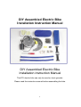
DIY Assembled Electric Bike
Installation Instruction Manual
DIY Assembled Electric Bike
Installation Instruction Manual
This DIY electric bike can only be used on level grounds.
Please read the instruction manual before assembling the bike.
1
The serial number of the motor on this bike is: __________________
2
Please have this manual well kept.
Store Stamp:
Purchase date: _______________________
1. Gear Assembly and Installation
3
Wheel Gear
Stator
4
To place the two parts of the gear separately on the spokes of the front or the back
wheel
To tighten the screws to complete the gear
5
Adjust the location of the gear so that the spokes will land inside of the grooves on
the gear.
The spokes should be positioned on the same side of the grooves.
6
To screw the stators (3-4 pieces) on to the gear loosely (approximately 50% tight)
7
Photo example of stators loosely screwed to the gear
Photo example of stators fully screwed onto the gear
Install 3 pieces of stators onto the gear with screws and have it loosely
(approximately 50% screwed) screwed onto the gear.
"DO NOT FULLY SCREW THE STATORS ONTO THE GEAR"
8
Measure the distance between the tire and the gear in 4 directions, up, down, left
and right and make sure all distances are the same, making the tire roughly
positioned on a concentric circle.
9
To spin the wheel quickly to create centrifugal force to adjust the gear position to be
concentric with the tire
When the gear and the front (back) wheel are concentric, tighten the screw to fasten
stators. (approximately 90% force)
Only 4-5 pieces of stators are necessary for the device to operate.
10
2. Motor Assembly:
(This is the most difficult process; please patiently follow the descriptions and photos
in this manual to assemble.)
1. Motor
2. Locking hole
3. Cable tie
4. Screw
5. Spinal plate
6. Gasket
This ruler is used to measure the distance from the wheel center to the location
where the motor is installed.
It can also be used to measure the distance between the wheel gear and the tire in
up, down, right and left directions.
The ruler is printed on the box, please cut it off if needed.
11
Installation position
Use the above-mentioned ruler to measure 17 cm starting from the wheel center,
label the position with a marking line.
(The correct position should be within 14-17 cm according to the brand of the bike
and please adjust accordingly.)
12
Position the inner part of the motor on the position of the marking line.
First swing motor to allow the screws to be set and then swing the motor to such a
position where the motor gear is located on the same line as the wheel gear.
13
The motor gear and the wheel gear on the same line, or else the chain will fall off
easily.
First, adjust the motor gear of the motor and the wheel gear to be roughly parallel
through visual inspection to determine how many gaskets to be put on the left side or
the right side of the motor gear to move the motor gear inward or outward until the
motor gear and the wheel are exactly on the same line. It is important that the motor
gear cannot crook or slant in any way.
* If the thickness of the front fork is different, apply additional gaskets to prevent the
slanting of the motor gear after assembly.
* All the gaskets can be used freely when necessary (if the provided gasket is
insufficient, paper boards and other material can be used as a replacement.)
* On some bike models the front forks are too slender for assembly, spinal plates can
be used according to the situation.
14
The motor gear and the wheel gear must be on the same line, and the three screws
on the motor inner part must be tightened to at least 80% tight. After the chain is set
around the motor gear and the wheel gear, the tightness of the chain must be
inspected to check the following situations:
1. Whether the tightness of the chain is equally spread out on the chain after the
assembling it onto the gears?
2. Double confirm whether the wheel gear is set concentric and make slight
adjustment if necessary.
3. The gears might slightly move out of location during the assembly process, please
make necessary slight adjustment before fasten the screws 100% tight to secure
the motor and also tighten the screws on the position securing holes illustrated as
follows.
Position securing holes
15
The wheel gear and the motor gear must be on the same line, or else the chain will
get loose easily.
If the motor is assembled on the back wheel where the steel frame is more slender,
the usage of spinal plates and gaskets for adjustment is recommended. (The motor
can be set at a proper location on either front or back wheel.)
Place the motor gear and the wheel gear on the same line and the position of the
gear can be adjusted by the height location of the motor and the usage of the spinal
plates.
After finishing the position adjustment, tighten the screws to fix the location of the
motor.
Tighten all screws after assembling the chain to the gear.
The usage of spinal plates
16
The spinal plates are used when assembling is to be made on the back wheel. (The
frame of the back wheel is more slender causing difficulty while assembling the
motor.)
If the front wheel fork is also slender for assembly, one spinal plate and gaskets can
be used for adjustment.
Two pieces of double-sided tape are enclosed for use after implementing the spinal
plate to have the spinal plate securely attached to the back wheel frame without
undesired skidding.
17
The usage of spinal plates in installation of motor
18
3. Chain Installation and Accessories
19
Connect the two ends of the chain with the connection buckle.
20
Chain installation instructions:
Do this while the motor is not yet tightly screwed to the bike frame. (approximately
95% tight)
Place the chain inside the front wheel fork or the back wheel fork and use buckle to
connect the two ends of the chain to form a circle.
First circle the chains around the motor gear, then around the wheel gear.
Slightly rotate the wheel to allow the chain to fully clip on to both gears.
Adjust the distance between the motor gear and the wheel to set the chain to proper
tightness and tightly screw the motor onto the frame.
21
4. Power Control System and Batteries
Power switch
To assemble the power switch, if the bike is provided with a derailleur, during the
assembling, the derailleur should be shifted to the lowest gear position, and then
move the position of the derailleur.
22
1. Power switch
23
After moving the derailleur, assemble the power switch next to the derailleur, where
your right thumb will be able to reach the power switch.
24
2. Power control box position
(1) Place the power control box at a suitable position, on the frame of the front wheel
or the back wheel.
25
3. Battery assembly
1. Battery case
2. Lithium-ion battery
3. Velcro
Insert the plug on the battery case into the battery hole
Battery related precautions:
1. When the battery is produced, a protection device is also implemented.
In case of power lose, and the battery can not restart, please remove the plug and
insert it again after 15 seconds, it should be able to restart again.
2. When the battery is not used, please do not insert the power plug into the battery
in order to prevent the leakage of electricity.
3. Remove the charger once the battery is fully charged and do not leave the charger
connected the battery.
4. Misuse of the lithium battery set might cause the battery to heat up and lead to a
fire hazard or explosion. Please take extra care while charging and maintaining the
battery set.
5. Please wait for the battery set to cool down before charging to prevent accidents
caused by the overheating of the battery.
6. Do not pierce, damage or disassemble the battery set and also do not place
battery near fire, heat source or inside any microwave or heating device.
26
Proper position for placing the battery
27
Methods for conserving battery power and battery protection:
For normal automobiles, motorbikes, and electric bikes, it consumes the most gas or
electric power during start up.
We recommend you to use the pedals to start the bike then turn on the power switch
to let the bike run electrically. This can help you save electricity and protect the
battery at the same time.
While parked, there are lock hole located on the motor, please use a lock to prevent
it from being stolen.
28
Precautions:
Gear Installation:
1. The spokes should be located on one side of the grooves on the gear.
2. Screw on 3 pieces of stators but do not 100% fasten the screws.
3. Cut the ruler printed on the box to measurement to ensure all distances on the up,
down, left, and right sides are identical.
4. Make proper adjustment for concentric arrangement before securely tightening.
Motor Installation:
1. If attempting to assemble the motor on the front wheel, please check the front fork
first to see if the size of the fork is the same or is top thick and bottom slender.
2. Cut down the ruler printed on the box, and use it to label the position of the motor
on the wheel fork.
17 cm if the fork is top thick bottom slender, and 14 cm if the fork is the same
thickness throughout.
Mark the position accordingly.
3. Assemble the motor to the marked location and the motor gear should
approximately be on the same line as the wheel gear.
Use gaskets to adjust the left/right position of the motor
4. If the wheel fork is too slender, spinal plates and gaskets can be used for position
adjustment.
If the wheel fork is not the same thickness throughout, gaskets can be used for slight
adjustment to prevent the motor gear from crooking or slanting.
5. The height of the motor gear can be adjusted by moving the motor and the
left/right positions can be adjusted by using spinal plates or gaskets.
6. When assembling the motor, first use three screws to mount the motor, however,
do not securely tighten the screw (80% tightened is recommended). Make sure the
wheel gear and the motor gear are positioned on the same line. Implement the
chains and adjust the height of the motor. Fasten the screw and lock the motor to
the frame when the chains are in proper tightness and position.
7. To prevent the motor from sliding down, tighten the screws on the position
securing holes after setting the gears to a straight line and installing the chains on
the gear. (Also consider the possibility of motor moving after fastening the screw
on the position-securing hole.)
29
Causes of chains coming loose:
1. The wheel gear and the motor gear should be located on a straight line.
2. The chain is too loose after being set to the wheel gear and the motor gear
(requiring adjustment of the position of the motor).
3. The motor gear might be crooked or slanted.
4. The motor is not tightly fixed and the motor vibrates during operation (not securely
fastened).
5. Motor might have slid down after long usage, causing the chain to come loose.
30
Warranty:
The stamp of the store is necessary upon the need of warranty. If no, the request will
be ignored.
Product warranty: one year after the purchase (Taiwan area only)
Service fee will be charged for below cases:
A. Damage caused by misuse of the product, modifications on the product, and
improper repairing.
B. Damage caused by improper transportation and handling after purchase.
C. Damage caused by natural disasters, public hazards, and improper usage.
D. Unauthorized change of warranty agreement.
Daily precautions:
1. While assembling the power switch and moving the derailleur, please adjust the
derailleur to the most common used gear, to ensure comfortable riding when the
battery is out of power.
2. Please remove the battery set when the bike is parked to prevent it from being
stolen.
3. The motor includes a lock hole; please use a lock when the bike is parked to
prevent it from being stolen.
31