1
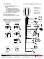
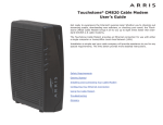
INSTALLATION MANUAL
INSTALLATION NOTES
Read and understand the following information prior to beginning the installation.
COMPATIBLE VEHICLES
This unit is for vehicles with +12V ignition, chassis ground.
MECHANICAL CONSIDERATIONS
1.
2.
3.
Securely solder all electrical connections.
Leave slack in the wires for maintenance and shrinkage.
Do not allow wires to rub against sharp edges. Use
grommets when running wires through holes in the car
body or firewall.
4. Protect and hide wires carefully. Make the wires
indistinguishable from factory wires.
5. After installation, wrap the color labels on the wires
with electrical tape or cover them with split loom.
6. Mount all components away from sources of extreme
heat or water.
7. Mount all components so they do not interfere with the
car’s normal operation.
8. Mount so that wires cannot be easily reached.
NOTE: Do not test with a test light. Only use a test meter
(VOM) to avoid damaging computers or setting off air bags.
IMMOBILIZER CONNECTION DETAILS
Circuit 1 (2-wire harness)—Starter solenoid
Find the wire that runs to the starter solenoid and is +12VDC
only while the engine is being started. Cut this wire. At this
time the engine should NOT be able to turn over or start.
Connect one end of the cut wire to one of the Circuit 1 wires,
and the other end to the second wire. Connection is nonpolar.
Circuit 2 (2-wire harness)—Ignition coil
Find the wire that runs to the ignition coil and is +12VDC
when the engine is started and running, but 0VDC when the
engine is off. Cut this wire. At this time, the engine should
be able to turn over but NOT start. Connect one end of the
cut wire to one of the Circuit 2 wires and the other end to
the second wire. Connection is non-polar.
GREEN label—Spare, Armed output to cut
fuel pump
Find the wire that runs to the fuel pump and is +12VDC
while the engine is starting or running, but 0VDC when the
engine is off. Cut this wire. At this time, the engine should
be able to turn over but NOT start. Connect the two ends of
the cut wire to the Green label wire with an optional heavyduty automotive relay as shown in the diagram on page 2.
RED label—+12VDC
Connect to a source of constant +12VDC. A 5A fuse is supplied.
BLACK label—2 Wire chassis ground
Connect each wire to a separate chassis ground location using
a factory bolt for best long-term reliability. If not possible,
ground to chassis with a metal screw and star washer.
YELLOW label—Ignition (MUST BE CONNECTED)
Connect to a wire or fuse that is +12VDC when the ignition
key is in the ON or START positions, and 0VDC when the
ignition key is in the ACC or OFF position.
WHITE label—Door sensor
1.
For vehicles with existing door switches—Find the wire
that is ground when any vehicle door is opened and
which shows a voltage when all doors are closed
(usually found in the driver’s kick panel). Connect this
wire to the White label wire.
2. For vehicles with no door switches—Mount a pin
switch in every door you wish to connect to the security
system. Connect each switch to the White label wire.
NOTE:
a. The SLI-762PP-ISS does not work with positive
trigger systems, if the connecting wire shows a
positive voltage when the door is open it will not
function.
b. This connection is not necessary for the operation
of the system, however using it can increase the
effectiveness of the SLI-762PP-ISS.
SLI-762PP-ISS CONNECTION DIAGRAM
LED MOUNTING
1.
2.
3.
Ask the customer where to mount the LED.
It must be easily visible from any direction, but should
not be exposed to direct sunlight.
To mount:
a. Press the LED out of its plastic receptacle.
b. Drill an 8mm hole in the desired LED location.
c. Press the receptacle into the hole from the front.
d. Press the LED into the receptacle from behind.
NOTES:
1. YELLOW label ignition wire
must be connected at all times
for proper operation.
2. RED label power wire must be
connected via 5A fuse.
3. Circuit 1 or Circuit 2 must be
used to disable the starter in
order to be consistent with
explanations in the Owner’s
Manual.
TESTING THE INSTALLATION
When the installation is complete, follow the Owner’s
Manual and completely test the unit.
MOUNTING THE CONTROL MODULE
Screw it onto the car body out of sight, or cable-tie to the
vehicle’s wire harness or other suitable location.
DEACTIVATION COIL INSTALLATION
Black 2-strand
NOTE: Be sure to inform the customer if you choose to
install the deactivation coil in a location other than
those shown below.
Best Range
Deactivation
Coil
LED
Two separate sources
of chassis ground.
(Black label)
(Black label)
Inferior Range
(White label)
Too far back
N.O. door (—) switch
Switched
+ 12VDC
(Yellow1 label)
. .
5A
(Red2 label)
(Green label) Circuit 3
Around
ignition
cylinder
Touches the
cylinder
(Brown label, circuit 3)
NOTE—This wire
must show + 12V
when the ignition
switch is in the ON
and START position.
* DIODE 1N4001
(optional)
Constant
+
12VDC
87
87a
86
30
85
ON and START position.
Fuel
Pump
Below
ignition
cylinder
Black heat shrink
Circuit 13
Circuit 1)
Correct
Incorrect
Angle faces away
from key
Best Range
Inferior Range
Black heat shrink
Circuit 23
No bends or kinks
in the antenna
Ignition coil
(White tube, Circuit 2)
Antenna is bent
NOTICE: The information and specifications printed in this manual are current at the time of publication. However, the SECO-LARM policy is one of continual development and
improvement. For this reason, SECO-LARM reserves the right to change specifications without notice. SECO-LARM is also not responsible for misprints or typographical errors.
®
SECOSECO-LARM U.S.A., Inc.
16842 Millikan Avenue, Irvine, CA 92606
Tel: 800-662-0800 / 949-261-2999 Fax: 949-261-7326
PITTW3
mi-SLI-762PP-ISS_1003.docx
.docx
Website: www.seco-larm.com
E-mail: [email protected]
Copyright © 2010 SECO-LARM U.S.A., Inc. All rights reserved. This material may not be
reproduced or copied, in whole or in part, without the written permission of SECO-LARM.