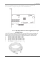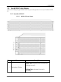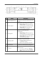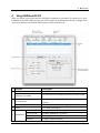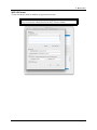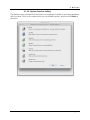
1
ExaSAN A12S2-PS User Guide Includes hardware setup information for: PCIe RAID System Models: A12S2-PS QSFP HBA Model: ACS-63200NT QSFP PCIe Cables Also includes software setup information for: RAID Management Software: RAIDGuard X Accusys, Inc., Feb. 4, 2013 Version: V1.4 Revision Sheet Revision Sheet Release No. V1.0 V1.1 V1.2 V1.3 V1.4 User Guide Date Revision Description 07/30/201 1 08/13/201 2 09/13/201 2 12/19/201 2 Initial release on CD. 02/04/201 3 Modify some wording and contents Add a half-high bracket picture in the packing list and modify the wording on the section 1.3.2 Modify page1-14, item 6 PCIe port expansion. Modify page 4-3(erase clear log explanation and add DAS and SAN log file path) Modify page1-8, add the power convertor to the packing list and accessory list Modify page1-12, the LED status of HDD tray when the HDD is expanded or migrated into an existed array. Modify page 3-3, the figure for installing HBA onto a PCIe x 16 slot. Page i PREFACE Notice The product features and specifications described in this guide are subject to change without notice. The manufacturer shall not be liable for any damage, or the loss of information resulting from the performance or use of the information contained herein. About This Guide Congratulations on your purchase of the ExaSAN (pronounced X-sa-SAN) A12S2-PS, a revolutionary high bandwidth streaming rack mounted storage system, specifically designed for all high-end post production storage. It delivers stability, exceptional performance, and scalable capacity at a very affordable ownership cost and requires only a low maintenance budget. This guide contains instructions for installing and using the ExaSAN A12S2-PS system and RAID (Redundant Array of Independent Disks) technologies and RAIDGuard X (ExaSAN’s RAID management software). If you are new to RAID and RAIDGuard X, this guide will help you become familiar with these technologies, and assist you in setting up and using RAID on the A12S2-PS. If you are already familiar with these technologies, use this guide as a reference for implementing your ExaSAN A12S2-PS RAID solution to achieve maximum performance and reliability. For details of hardware installation, setup, configuration and considerations, see • Chapter 1, “Introducing ExaSAN PCIe2.0 Storage System” • Chapter 2, “Preparing to Install ExaSAN A12S2-PS” • Chapter 3, “Installing ExaSAN A12S2-PS” • Chapter 4, “Using RAIDGuard X” • Chapter 5, RAID Overview Guide to Conventions Important information that users should be aware of is indicated with the following icons: Caution This icon indicates the existence of a potential hazard that could result in personal injury, damage to your equipment or loss of data if the safety instruction is not observed. User Guide Page ii Note This icon indicates useful tips on getting the most from your Accusys RAID system. Trademarks Accusys and the names of Accusys products and logos referenced herein are trademarks and/or service marks or registered trademarks and/or service marks of Accusys, Inc. Xsan, Mac, Mac OS, and Macintosh are either registered trademarks or trademarks of Apple. Other product and company names mentioned herein may be trademarks and/or service marks of their respective owners. All contents of this manual are copyrighted by Accusys, Inc. The information contained herein is the exclusive property of Accusys, Inc. and shall not be copied, transferred, photocopied, translated on paper, film, electronic media, or computer-readable form, or otherwise reproduced in any way, without the express written permission of Accusys Inc. Document version 1.0 Date Published: November, 2011 © Copyright 2011 Accusys, Inc. All Rights Reserved. This device complies with Part 15 of the FCC Rules. Operation is subject to the following two conditions: (1) this device may not cause harmful interference, and (2) this device must accept any interference received, including interference that may cause undesired operation. User Guide Page iii ExaSAN A12S2-PS User Guide TABLE OF CONTENTS Page # Notice .....................................................................................................................................................ii About This Guide ...................................................................................................................................ii Guide to Conventions ..........................................................................................................................ii Trademarks ........................................................................................................................................... iii 1. Introducing ExaSAN PCIe 2.0 Storage System ............................................................ 1-1 1.1 System Overview ................................................................................................... 1-1 1.2 Unpacking the System .......................................................................................... 1-7 1.3 What’s in the Box ................................................................................................... 1-8 1.4 SAS JBOD Expansion ............................................................................................. 1-9 1.5 Your A12S2-PS at a Glance ................................................................................ 1-10 1.1.1 What is the ExaSAN Solution ..................................................................................................1-1 1.1.2 What is the ExaSAN A12S2-PS Solution.................................................................................1-2 1.1.3 ExaSAN A12S2-PS Components and Accessories .............................................................1-3 ExaSAN PCIe RAID Disk System ....................................................................................1-3 1.1.3.1 Hard Disk Drive (HDD) for the RAID System................................................................1-3 1.1.3.2 ExaSAN QSFP Host Bus Adapter (ACS-63200NT) .......................................................1-3 1.1.3.3 QSFP (Quad Small Form-factor Pluggable) PCIe Copper or Optical Cables ....1-4 1.1.3.4 Power Cord & Power convertors .................................................................................1-5 1.1.3.5 Rail and Rail Extender ....................................................................................................1-5 1.1.3.6 1.1.4 Key Features .............................................................................................................................1-5 1.2.1 1.2.2 1.2.3 1.3.1 1.3.2 1.3.3 What Is In Your Order ..............................................................................................................1-7 Checking the Equipment You’ll Need ................................................................................1-7 Unpacking.................................................................................................................................1-8 The ExaSAN RAID .....................................................................................................................1-9 ExaSAN Accessories ................................................................................................................1-9 Disk Tray package ...................................................................................................................1-9 1.5.1 ExaSAN A12S2-PS ...................................................................................................................1-10 A12S2-PS Front Panel....................................................................................................1-10 1.5.1.1 Beeper Codes ...............................................................................................................1-11 1.5.1.2 Disk Mapping.................................................................................................................1-12 1.5.1.3 Disk Tray ..........................................................................................................................1-12 1.5.1.4 A12S2-PS Rear Panel ....................................................................................................1-13 1.5.1.5 A12S2-PS SAS JBOD Rear Panel .................................................................................1-15 1.5.1.6 1.5.2 ExaSAN QSFP Host Bus Adapter (HBA)...............................................................................1-17 2. Preparing to Install ExaSAN A12S2-PS ......................................................................... 2-1 2.1 Precaution for Handling the System..................................................................... 2-1 2.2 Choosing the Location for the System ................................................................. 2-1 2.3 Electrical Power ..................................................................................................... 2-1 User Guide Page iv 3. 2.4 Operating Environment ......................................................................................... 2-2 2.5 Security................................................................................................................... 2-2 Installing the ExaSAN A12S2-PS.................................................................................... 3-1 3.1 Installing the System.............................................................................................. 3-1 3.2 Powering the System On and Off ......................................................................... 3-7 3.3 ExaSAN GUI RAIDGuard X Overview ................................................................... 3-7 3.1.1 3.1.2 3.1.3 3.1.4 3.2.1 3.2.2 Installing Disk Drives .................................................................................................................3-1 Installing the HBA Card ...........................................................................................................3-2 Connecting the HBA to the A12S2-PS System ....................................................................3-4 Installing the rail on A12S2-PS System ..................................................................................3-5 Powering On .............................................................................................................................3-7 Powering Off .............................................................................................................................3-7 3.3.1 RAIDGuard X Key Features ....................................................................................................3-8 3.3.2 Installation prerequisites .........................................................................................................3-8 3.3.3 Before You Start .......................................................................................................................3-8 3.3.4 Installing the driver and RAIDGuard X ...............................................................................3-10 Installing RAIDGuard X on MAC and Windows ......................................................3-10 3.3.4.1 Installing ExaSAN RAID system driver on Linux .........................................................3-13 3.3.4.2 3.3.5 Confirm the ExaSAN RAID system driver on OS ...............................................................3-18 Confirming the ExaSAN RAID system driver on Mac .............................................3-18 3.3.5.1 Confirming the ExaSAN RAID system driver in Windows .......................................3-19 3.3.5.2 3.3.6 Confirm LEDs on HBA ............................................................................................................3-20 4. Using RAIDGuardX GUI ................................................................................................. 4-1 4.1 Accessing the RAIDGuardX GUI .......................................................................... 4-2 4.1.1 RAIDGuard X Client and Server ............................................................................................4-2 4.1.2 RAIDGuard X Menu Bar ..........................................................................................................4-3 Adding and Removing Controllers .............................................................................4-5 4.1.2.1 Planning your RAID .........................................................................................................4-9 4.1.2.2 Creating and Deleting an Array................................................................................4-11 4.1.2.3 Controller Info ................................................................................................................4-18 4.1.2.4 Formatting and Mounting Arrays ..............................................................................4-21 4.1.2.5 Email Notification Setting ............................................................................................4-21 4.1.2.6 Preference Setting........................................................................................................4-23 4.1.2.7 4.1.2.7.1 Mode .........................................................................................................................4-23 4.1.2.7.2 Cache .......................................................................................................................4-26 4.1.2.7.3 MISC ...........................................................................................................................4-27 Options Function Setting .............................................................................................4-29 4.1.2.8 4.1.2.8.1 Slicing .........................................................................................................................4-30 4.1.2.8.2 LUN Map ....................................................................................................................4-33 4.1.2.8.3 Expansion ..................................................................................................................4-36 4.1.2.8.4 Migrations..................................................................................................................4-39 4.1.2.8.5 Snapshot ...................................................................................................................4-42 4.1.2.8.6 Health Center...........................................................................................................4-47 4.1.2.8.7 Unlock Drives ............................................................................................................4-49 4.1.3 Updating the ExaSAN RAID system Firmware ..................................................................4-52 Preparing the Firmware Update Files .......................................................................4-52 4.1.3.1 Installing the Firmware Update Files..........................................................................4-52 4.1.3.2 User Guide Page v 5. RAID Overview .............................................................................................................. 5-1 5.1 How RAID Works .................................................................................................... 5-1 5.2 Data Storage Methods .......................................................................................... 5-1 5.3 RAID Levels............................................................................................................. 5-2 5.2.1 5.2.2 5.2.3 5.3.1 5.3.2 5.3.3 5.3.4 5.3.5 Data Striping .............................................................................................................................5-1 Data Mirroring ..........................................................................................................................5-1 Data Parity ................................................................................................................................5-2 User Guide RAID 0: Striping .........................................................................................................................5-2 RAID 1: Mirroring .......................................................................................................................5-2 RAID 5: Independent data disks with distributed parity...................................................5-2 RAID 6: Independent data disks with two Independent parity schemes ....................5-2 RAID 0+1: Striped set with Mirroring ......................................................................................5-3 Page vi 1. Introduction 1. User Guide Introducing ExaSAN PCIe 2.0 Storage System 1. Introduction 1. 1.1 Introducing ExaSAN PCIe 2.0 Storage System System Overview Your new ExaSAN (pronounced “X-sa-SAN”) PCIe 2.0 Storage System is a rack mounted storage that can be used as a DAS (Direct-Attached Storage) or SAN (Storage Area Network) for the post production and broadcasting industries that require high bandwidth. Furthermore, the A12S2-PS supports the latest PCIe 2.0 standard providing a 20Gb bandwidth. 1.1.1 What is the ExaSAN Solution Developed by Accusys, Inc., a worldwide leader in RAID (Redundant Array of Independent Disks) storage systems, ExaSAN is a system solution built for simple, costeffective deployment and storage management. Employing PCIe (PCI Express) technology, the PCIe 2.0 Storage System uses QSFP cabling technology to natively transmit at low latency PCI Express Gen 2 protocol. Each channel under PCIe 2.0 can transmit at 500MB/s, giving PCIe 2.0 x4 storage systems a 20Gb bandwidth and PCIe 2.0x8 a 40 Gb bandwidth. The ExaSAN total solution, including its complete line up of rack mount system, tower systems, PCIe switch systems and accessories, puts the benefits of shared, scalable, and high-performance storage within easy reach of organizations with limited IT resources and budgets. Post production work such as non-linear editing (NLE) requires especially high bandwidth storage to support the volume of data being processed, and ExaSAN storage solution is designed to meet such demands. The high bandwidth enabled by ExaSAN technology allows the client to achieve the maximum efficiency with minimum cost, while its enhanced functionality provides continuous and smooth data transfer to prevent frame drop or lagging of projected content. ExaSAN is a complete solution that includes the PCIe RAID system, cable and HBA card. Figure 1 below depicts the ExaSAN A12S2-PS system solution architecture. Note that it can be expanded from one RAID system to three systems (daisy-chaining from 1x RAID controller). User Guide Page 1-1 1. Introduction Figure 1 Whether it’s collaborative video editing in a post-production workgroup, or a shared research project in a university, the ExaSAN solution offers a range of performance levels and storage capacities that scale to meet the needs of small-to-medium-sized organizations. Equally important is its integrated design, centralized administration and monitoring, and a suite of built-in management tools; which eliminate the need for a staff of experts to install and maintain a SAN for the workgroups. Figure 2 below depicts a standard ExaSAN system solution architecture. Figure 2 1.1.2 What is the ExaSAN A12S2-PS Solution The ExaSAN A12S2-PS is a 2U12Bay disk array system designed for all high-end post production storage usage, with the latest interface technology PCIe 2.0 and innovative green design, supports RAID level 0, 1, 5, 6, 0+1, high speed 6Gb SAS drives, and high capacity SATA II drives. The Single port RAID controller of A12S2-PS combined with 12 drives can provide 20Gb bandwidth with its unique Performance Optimization feature. Your ExaSAN A12S2-PS system consists of the standard components listed below in this section. Note that items 1 through 5 are Accusys-supplied equipment as part of the User Guide Page 1-2 1. Introduction A12S2-PS package. The host server and HDD in a DAS/SAN environment are not Accusys-supplied equipment and are therefore not included in the package. Contact your System Integrator/Value Added Reseller if you need assistance in purchasing these components. 1. ExaSAN A12S2-PS PCIe RAID storage system, see Section 1.1.3.1 and 1.1.3.2 2. QSFP-PCIe 2.0 Host Bus Adapter, compatible with PCIe 2.0 and 1.1 slots on the host server, see Section 1.1.3.3 3. QSFP 2M copper for connecting the host and HBA, optical and variety length is optional, see Section 1.1.3.4 4. 2 AC Power cords, see Section 1.1.3.5 5. Rail and rail extender for mounting the A12S2-PS on a rack, see Section 1.1.3.6. 1.1.3 ExaSAN A12S2-PS Components and Accessories This section provides detailed description of each system component and accessory. 1.1.3.1 ExaSAN PCIe RAID Disk System The A12S2-PS is a 2U rack mounted RAID system supporting up to 12 hot swappable hard drives (sold separately). Also note that the RAID disk system comes with a chassis, RAID controller, and disk trays only. The hard disk drives (HDDs) are not included. See Section 1.1.3.2 for considerations concerning HDDs. Further note that a QSFP Host Bus Adapter is packaged with the PCIe RAID system. In a DAS (Direct Attached Storage)/SAN (Storage Area Network) configuration, this card is to be installed in the host system to provide the PCIe interface with the RAID system. 1.1.3.2 Hard Disk Drive (HDD) for the RAID System This component is ordered separately from a third-party vendor. The quantities depend on the number and model of RAID systems you have. Consult your RAID system User Guide for additional information. Hard disk drives come in different storage capacities performance levels. However, be aware that all hard drives in a RAID system should match in size and speed. Furthermore, all hard drives in an array should be of identical model with the same firmware version. Accusys recommends the SAS and SATA Enterprise HDDs for your RAID disk systems. 1.1.3.3 ExaSAN QSFP Host Bus Adapter (ACS-63200NT) Make sure that each client system in your workgroup has an available PCIe x4, x8, or x16 slot. Note that the PCIe slots on some motherboards are for graphics cards only. Check your motherboard documentation or verify with the motherboard vendor for compatibility with the Accusys-supplied HBA. Also note that some PCIe x4 or x8 slots only User Guide Page 1-3 1. Introduction share or run at PCIe x1 speed. You are advised to consult your motherboard documentation to verify the real speed of the available PCIe slot. 1.1.3.4 QSFP (Quad Small Form-factor Pluggable) PCIe Copper or Optical Cables A 2m QSFP Copper Cable is included in your Accusys RAID disk system package. It is used to connect the host systems to the storage system. Use the copper cable for distances up to 5 meters. Optional QSFP cables are available at varying lengths. 1. 2m QSFP Copper Cable, (black in color) 2. 5m QSFP Copper Cable, (black in color) 3. 10m QSFP Optical Cable, (orange in color) 4. 30m QSFP Optical Cable, (orange in color) 5. 50m QSFP Optical Cable, (orange in color) 6. 100m QSFP Optical Cable (orange in color) User Guide Page 1-4 1. Introduction 1.1.3.5 Power Cord & Power convertors Two AC Power Cords are included in the SWF16 package. We also provide three types of power convertors – EK, AU, EU, in addition to the US standard power cord. . 1.1.3.6 Rail and Rail Extender This accessory is included in your RAID system package. It is used to mount the A12S2-PS system onto a standard 19” rack. 1.1.4 Key Features Below are the key features of the system. They are the reasons why ExaSAN is your top RAID solution for a power user, working on high-end personal work. 1. Host Interface • PCI Express Gen2 5Gb/S x4, transfer up to 20Gb/S 2. Disk Interface • Supports 12x SAS/SATA 6Gb and SSD disks • Supports 3.5”/2.5" hard disks • Supports 3TB hard disks 3. RAID Controller Specifications • • Hardware XOR/Multi-Parity engine 2GB DDRII-800 memory, ECC-protected, support up to 4GB 4. Software Specifications • Multiple RAID levels: 0,1,5,6, 0+1, and JBOD • UP to 4 independent disk arrays • RAID capacity partitioning: up to 16 slices User Guide Page 1-5 1. Introduction • • • • Support up to 64 LUNs Variable stripe sizes: 8, 16, 32, 64, 128, 256 (KB) Selective initialization method with background initialization Online RAID set expansion and level migration • • Controller and Disk Cache Control to optimize read/write performance Support write-back and write-through caching • Automatic drive insertion/removal detection and fast disk rebuilding • Online bad block data recovery and reallocation • Online disk scrubbing and data refresh and parity regeneration • Disk health monitoring by S.M.A.R.T. • NVRAM-based transaction log and auto parity resynchronization • Array roaming and disk traveling with redundant on-disk metadata • Array recovery to restore RAID configurations • Dual firmware images for firmware recovery • Disk lag proof technology to guarantee disk timely exposure • Equalization mode to smooth the performance of sequential 5. Management • Java-based GUI, cross-platform executable • Enclosure components monitoring and control via GUI • LED indicator for RAID & enclosure status • Event logging to text file with event viewer • Event notification by email (SMTP) • Centralized multiple RAID system management • Supports both in-band and out-band management • Supports RAID management by EFI and BIOS • Support firmware upgrade via GUI • Support CLI (Command Line Interface) • Support SNMP • Support remote management 6. Enclosure • Modularized components design, Power module and Fan module support hotpluggable. • FAN, Power, Temperature status LED indication in the front handle. • 80plus power can be above 80% providing the energy conversion efficiency with more power bill savings • Power supply also supports Power Management Bus (PMBus) protocol allowing it to monitor power supply status and performance from RAIDGuard X • Dimensions: 88mm(H) x 483mm(W) x 597mm(L) 7. Supported OS User Guide Page 1-6 1. Introduction • • • Windows XP/2003/Vista/2008 and Windows 7(32/64-bit, Miniport and Storport driver, WHQL certified) Linux: Red Hat, SUSE, Fedora, CentOS, Debian, etc. MAC: OS X( 10.5, 10.6, 10.7 and later) 8. Operating Conditions • Humidity: 5% - 85% • Operating Temperature: 0C – 40C • Certification: RoHS, UL, CE, FCC, C-Tick, BSMI 9. QSFP HBA • • 20Gb/s PCIe Channel PCIe2.0 x4 Short, low profile, form factor card • Dimension 110 x 68.9 mm • Standard bracket (low profile available) 10. QSFP Cable • Connector PCI Express 2.0 x4 • Copper cable support Length: 2M, 5M • Optical cable support Length: 10M, 30M, 50M, 100M 1.2 Unpacking the System Your ExaSAN A12S2-PS is shipped in special packaging to provide protection during transportation, as well as to facilitate simple and safe removal from the carton(s). Note that different components may be shipped in separate cartons. 1.2.1 What Is In Your Order Your ExaSAN System Integrator/Value Added Reseller should have helped you assess, identify, and order all necessary system components and accessories. If you ordered the complete system solution, your order includes everything described in Section 1.3. Note that there are generic system components and accessories required by the ExaSAN solution architecture, but they are not sold by your ExaSAN System Integrator/Value Added Reseller and therefore not included in your ExaSAN A12S2-PS order. Please refer to Section 1.5, “What Else You Need” for additional information. 1.2.2 Checking the Equipment You’ll Need Section 1.1.3 has a complete list of all the equipment you’ll need to set up the ExaSAN A12S2-PS. Check carefully against that list; verify that you have all of the system components and accessories before commencing hardware installation. User Guide Page 1-7 1. Introduction 1.2.3 Unpacking Follow the steps below to open the carton and remove the system from its packaging. Keep in mind that you should work with a second person if heavy lifting is a concern for you. 1. Read Chapter 2, “Preparing to Install ExaSAN A12S2-PS.” 2. Remove any packing material on the outside of the carton. 3. Cut the tape at the top of the carton. If you use a long cutting instrument, exercise care to avoid damaging the content inside. 4. Open up the top flaps of the carton to reveal the content inside. Remove the protective foam on top of the system. Carefully remove each item from inside the carton. 1.3 What’s in the Box Carefully check your carton contents against the included packing list, or the inside flap of the box, and your original purchase order. You should have the items as described in the sections below. User Guide Page 1-8 1. Introduction Contact your Accusys System Integrator/Value Added Reseller or Accusys Customer Service (see Appendix C “Customer Service and Technical Support” for more information) to report any missing item. 1.3.1 The ExaSAN RAID Your ExaSAN RAID disk system carton contains the following items: 1. PCIe 2.0 RAID disk system - A12S2-PS (x1) 2. Accessories package (x1) 3. Disk tray package (x1) 1.3.2 ExaSAN Accessories The Accessories package includes the following items. These items can also be ordered, packaged, and shipped separately from Accusys. 1. QSFP Host Bus Adapter (x1) 2. Half-high bracket (x1) for full-high bracket replacement 3. 2M QSFP copper cable (x1) 4. AC power cord cable (x2) 5. Installation CD (x1) 6. Quick Start Guide (x1) 7. Rail set (x2) 8. Rail extender (x2) 9. Screw pack for disk tray (x2) 10. Screw pack for rack (x2) 11. Power converter UK, EU, AU to US (x3) 1.3.3 Disk Tray package The Disk Tray package is divided into two layers. Each layer holds 6 disk trays, with a total of 12 disk trays. 1.4 SAS JBOD Expansion The SAS JBOD Expansion is sold separately from the A12S2-PS. The SAS JBOD expansion uses 2U 12 drive rack mount chassis similar to the A12S2-PS. The SAS JBOD expansion can be daisy-chained, up to maximum of 3 units, from a single A12S2-PS to expand capacity to a maximum of 48 hard drives (including the A12S2-PS). The SAS JBOD expansions can be controlled off a single A12S-PS RAID controller, providing a cost effective solution to expanding the RAID capacity. Note The SAS JBOD is not equipped with a RAID controller and thus can not be used independently of the A12S2-PS. User Guide Page 1-9 1. Introduction 1.5 Your A12S2-PS at a Glance This section helps you get familiar with the physical appearance of your ExaSAN A12S2PS. 1.5.1 ExaSAN A12S2-PS 1.5.1.1 Item A12S2-PS Front Panel Name Description Steady Blue indicates the controller A is working normally. 1 Controller A Status Flashing Blue indicates the host is accessing. User Guide Page 1-10 1. Introduction Steady Red indicates the controller A has failed. Flashing Red Other error. Steady Blue indicates the fan modules are working normally. 2 System Fan Steady Red indicates one or more of the fan modules failed. Steady Blue indicates the system temperature is under the preset value. 3 System Temperature Steady Red indicates the system temperature is over the preset value. Steady Blue indicates the subsystem power supplies are working normally. 4 System Power Steady Red indicates that a power supply has failed. Pushing the button will turn off the system beeper when beeper is sounding. If another abnormal event occurs, the beeper will alarm again. 5 Mute Button If you want to disable the beeping all the time, please use GUI of the RAID system and find the “Preference”to uncheck the “Beeper”. For more information, please refer to the section 4.1.2.7 1.5.1.2 Beeper Codes Controller Status User Guide Beeper mode Page 1-11 1. Introduction Turn on the Controller System Panic Controller Work Status, ex: Disk init, disk rebuild, disk expansion, disk migratrion, disk snapshot, etc. System Problem, ex: Fan issue, Power issue, RAID error, etc. Create array successfully Open the Beeper setting Memory test error One short beep Long beep Regularly repeating one short beep Regularly repeating three short beeps One short beep Two short beeps Regularly repeating three rapid short beeps 1.5.1.3 Disk Mapping Disk 1 Disk 2 Disk 3 Disk 4 Disk 5 Disk 6 Disk 7 Disk 8 Disk 9 Disk 10 Disk 11 Disk 12 1.5.1.4 Disk Tray Disk Status LED #1 LED #2 Disk Online Steady Green Disk Fail Steady Red No Disk Steady Red Disk Lock Steady Green User Guide Page 1-12 1. Introduction Disk Access Flashing Blue Steady Green Disk Initialization Flashing Blue Steady Green Disk Rebuild Flashing Blue Disk Expansion Flashing Blue Rebuild Drives: Steady Red Original Drives: Steady Green Extend Drives: Rotating Green & Red Original Drives: Steady Green Migrating Drives > Original Drives • Migrating Drives: Rotating Green & Red • Original Drives: Steady Green Migrating Drives < Original Drives Disk Migration Flashing Blue • Migrating Drives: Rotating Green & Red • Original Drives: Steady Green Migrating Drives = Original Drives Disk of Health Center Action Flashing Blue 1.5.1.5 User Guide • Migrating Drives: Steady Green • Original Drives: Steady Green Steady Green A12S2-PS Rear Panel Page 1-13 1. Introduction No. 1 Name Power Supply AC In Description Connects to a power cable and power source. Removable redundant power supply 1 2 • Steady Green LED indicates the power supply is working normally. • Steady Red LED indicates the power supply has failed. Power supply 1 Prevents the disk array from overheating. 3 Cooling fan 1 • Steady Green LED indicates the fan modules are working normally. • Steady Red LED indicates that a fan module has failed. Indicates the controller status 4 5 6 Heartbeat LED Terminal port PCIe port User Guide • Flashing Green indicates the controller is active • LED is off if controller is inactive. Connects to maintenance equipment. Connects the controller to the HBA on the host server. • Host access LED (top): Flashing Blue indicates host accessing is in Page 1-14 1. Introduction progress • Host connected LED (bottom): Steady Green indicates the controller is connected normally. Expansion port for SAS JBOD. 7 • JBOD connected LED (top): Steady Green indicates that JBOD is connected normally. • JBOD access LED (bottom): Flashing Blue indicates controller accessing is in progress SAS port 8 Controller Provides access to the hard disk drives. 9 Cooling fan 2 Prevents the disk array from overheating. Removable redundant power supply 2 10 • Steady Green LED indicates the power supply is working normally. • Steady Red LED indicates the power supply has failed. Power supply 2 11 Power Supply AC In Connects to a power cable and power source. 12 Power supply switch Switches the power on or off. 1.5.1.6 User Guide A12S2-PS SAS JBOD Rear Panel Page 1-15 1. Introduction No. 1 Name Power Supply AC In Description Connects to a power cable and power source. Removable redundant power supply 1 2 • Steady Green LED indicates the power supply is working normally. • Steady Red LED indicates the power supply has failed. Power supply 1 Prevents the disk array from overheating. 3 Cooling fan 1 • Steady Green LED indicates the fan modules are working normally. • Steady Red LED indicates that a fan module has failed. Indicates the controller status 4 Heartbeat LED • Flashing Green indicates the controller is active • LED is off if controller is inactive. 5 Left SAS port Expansion port for SAS JBOD. 6 Right SAS port Cascade upstream to RAID or JBOD system. Prevents the disk array from overheating. 7 Cooling fan 2 • Steady Green LED indicates the fan modules are working normally. • Steady Red LED indicates that a fan module has failed. Removable redundant power supply 2 9 Power supply 2 User Guide • Steady Green LED indicates the power supply is working normally. • Steady Red LED indicates the Page 1-16 1. Introduction power supply has failed. 10 Power Supply AC In Connects to a power cable and power source. 11 Power supply switch Switches the power on or off. 12 JBOD ID Indicates the ID of the JBOD expansion ID Range: 1 to 7 1.5.2 ExaSAN QSFP Host Bus Adapter (HBA) No. 1 2 Name Description QSFP Connector Port For connection with one of the Host Module Ports on the switch rear panel or A12S2-PS directly. Jumper Switch LED Indicator User Guide • Off (no light at all) indicates the jumper pin in question is set to “On” position. In this state, the card is ready for DAS direct connection with the ExaSAN A12S2-PS. • Solid amber indicates the jumper pin in question is set to “1” position. In this state, the HBA card is ready for a SAN connection. See Section 3.1.2, “Installing the HBA Card,” for additional information. Page 1-17 1. Introduction 3 4 Link LED Indicator Access LED Indicator User Guide • Solid green indicates connected PCIe 2.0 link; • Flashing green indicates connected PCIe 1.0 link or downgraded speed. • Off (no light) when there is no link or indicates a link with trouble. Flashing blue while there are data access activities with the connected device. Page 1-18 2. Preparation 2. User Guide Preparing to Install ExaSAN A12S2-PS 2. Preparation 2. Preparing to Install ExaSAN A12S2-PS To ensure safe and smooth operation of your ExaSAN A12S2-PS, it is essential that you choose an appropriate location for the system, and provide an appropriate operating environment and adequate power for all components of the system. As you plan for installation, follow the guidelines below to ensure that the system and its environment are safely and appropriately positioned for efficient operation and service. 2.1 Precaution for Handling the System Take the following precautions to avoid damages to the system or potential injury to you. 1. Prepare a flat, sturdy surface before removing the system from its packaging. The table or cart that will hold the system should be as close as possible to the system’s carton. 2. Ensure that all power switches have been turned off and all power cords disconnected to prevent personal injury and damage to the hardware. 3. Static electricity can damage electronic components of your system. Follow the guidelines below to avoid such damage: a. Work in a static-free environment b. Wear a grounded anti-static wrist strap c. Store uninstalled components in anti-static bags d. Handle circuit boards by their edges and avoid touching chips and connectors 2.2 Choosing the Location for the System The ExaSAN A12S2-PS is designed as a rack mount system. Depending on where your rack mount is located, you should keep the following points in mind when determining where to place your system. 1. Measure the amount of available space in your rack mount. The amount of space required for the A12S2-PS is 2U. 2. Measure the distance between any two components that need to be connected via cable(s). This measurement will help you determine the length of the required cable(s). Or if you’ve already purchased the cables, determine the proximity of the components in question. 3. Leave sufficient room, at least two inches, around the unit to allow air ventilation. 4. Do not block or cover any of the ventilation holes in the front and back panels of the unit. Consistent airflow is essential to keeping the system operating efficiently. 5. Allow additional room at the front and back of the unit for service. 6. The ExaSAN A12S2-PS uses several cables and cords. It’s a good idea to determine how they will be arranged at the rear of the system, and where the cables will be routed to connect to the host systems and RAID disk systems. 2.3 Electrical Power At your chosen location for the ExaSAN A12S2-PS, make sure that the electrical circuitry and power outlets are sufficient for the combined power needs of all hardware User Guide Page 2-1 2. Preparation components. To plan for safe and adequate power to the system, follow these guidelines: 1. Check the documentation for all hardware components at the chosen location to determine their power requirements. Then make sure that the available power supply for that location is sufficient for the planned components. 2. If you need assistance determining the power needs of the components at the chosen location, consult an electrical expert who is familiar with your facility. 3. If there are devices at the chosen location that use large amounts of power, use surge protectors or power conditions as part of the installation. 4. When planning for electrical power, make sure you have more power than the total power requirements specified for all components. Also make certain that the power load is distributed evenly among circuits to that location. Consult an electrician or other expert if you need assistance with planning for the power needs of your components. 5. Make sure that the power outlets for all hardware components are grounded according to local and national standards. Consult an electrician if you need assistance with grounding. 2.4 Operating Environment The operating environment for the ExaSAN A12S2-PS must meet certain requirements: 1. Verify that the temperature range of the chosen location is within the limits established for the system and all other components. 2. Make certain that the chosen location has adequate ventilation to maintain the necessary temperature range. 3. If there are multiple hardware components installed at the chosen location, consider additional cooling measures to assure efficient operation of the system and other components. 4. Environment parameters: a. Operating temperature: 0°C to 40°C (32°F to 104°F) b. Non-operating temperature: -40°C to 70°C (-40°F to 158°F) c. Operating humidity: 5-85%, non-condensing d. Storage humidity: 0-95%, non-condensing 2.5 Security To ensure the security of the ExaSAN A12S2-PS, make certain that the chosen location is secure and that only authorized staff members or technicians can gain access to this location. User Guide Page 2-2 3. Installation 3. User Guide Installing the ExaSAN A12S2-PS 3. Installation 3. Installing the ExaSAN A12S2-PS Follow the steps in this chapter to prepare your ExaSAN A12S2-PS system for installation. 3.1 Installing the System Follow the instructions in this section to hook up all your hardware components of the ExaSAN A12S2-PS system. Do not turn the power of any individual component on until instructed. When all components are properly connected, follow the instructions in section 3.3.1 “Powering On” to turn the components on in the prescribed order. 3.1.1 Installing Disk Drives Follow the steps below to install your HDDs. Refer to the applicable RAID disk system User’s Guide and Quick Start Guide for additional information. 1. With the connectors facing outward, insert the HDD into the disk tray. 2. Slide the HDD outward until the connectors align with the edge of the disk tray. 3. Secure the HDD to the disk tray with two screws on each side. 4. Slide the disk tray into the disk bays on the front of the chassis. User Guide Page 3-1 3. Installation 5. Push the tray inward until the tray firmly connects and you hear the tray click into place. 6. Repeat for all drives to be installed into the A12S2-PS. Note The hard drives in a RAID system should match in size and speed. All drives in an array should be of identical model with the same firmware version. 3.1.2 Installing the HBA Card Before the ExaSAN A12S2-PS is ready to be connected and powered on, you must install the HBA card in the workgroup client system. The HBA card is compatible with PCIe x4, x8, and x16 slots. If a choice is given, use the fastest PCIe slot available. Although the HBA card is compatible with both PCIe 1.1 and 2.0 standards, only the latter is recommended due to performance consideration. Caution PCIe slots on some motherboards are for graphics cards only. Check with the motherboard vendor for compatibility. Follow these steps to install the card in each host system: 1. Make sure that the client system is turned off. 2. Open the client system’s outer casing cover, check with your vendor documentation for instructions if necessary. 3. Re-position the HBA card so that you are facing jumper switch as shown below. You can use the jumper switch to configure the HBA for DAS or SAN usage. Set the jumper switch before installing into the host • DAS mode: When the switch is in the "On” position, the HBA card is enabled for RAID (Direct-Attached Storage A12S2-PS) mode. • SAN mode: In the “1” position, the HBA is enabled for switch (SAN) mode. User Guide Page 3-2 3. Installation 4. Locate the available PCIe slot; remove the blank plate if one is present, save the screw for later use. 5. Position the connector of the card over the slot, insert the connector into the slot, press gently but firmly until it is securely seated. User Guide Page 3-3 3. Installation 6. Use the screw that you saved in step 2 to secure the metal bracket of the card to the system case. 7. Replace the outer casing cover. 3.1.3 Connecting the HBA to the A12S2-PS System 1. Connect the HBA to the ExaSAN A12S2-PS with a QSFP PCIe cable. Insert one end of the QSFP cable into one of the host module ports on the rear panel of A12S2-PS. Your cable connector is securely plugged when you hear a click. If you need to unplug the cable, pull the ring on the connector firmly until it is detached from the port. Note that the QSFP used in the photo illustration below is a QSFP optical cable. If the distance between the switch and the host system is less than 5 meters in your case, you might have order the QSFP copper cable for this purpose. 2. Insert the other end of the cable into the PCIe port on the HBA card, which you installed on the host system earlier in Section 3.1.2. The cable connector is securely plugged when you hear a click. User Guide Page 3-4 3. Installation 3. Plug a power cord into the AC power-in port in the storage system; do not turn power on yet. Caution Once powered on, Do NOT remove the QSFP PCIe cable when in use to avoid data loss and corruption. 3.1.4 Installing the rail on A12S2-PS System Your disk array is designed to be mounted in 2U slot on a standard 19-inch rack. The ExaSAN A12S2-PS is shipped with the controller installed, and ready to be mounted. It is recommended to mount the disk array before installing the hard disk drives. You may need to install rail extenders to properly secure the disk array. To install the rail extenders: 1. Attach the rail extenders and secure with two screws. User Guide Page 3-5 3. Installation 2. Slide the disk array into the rack and secure into place with the fixing screws. To mount the disk array in a rack: 1. Attach eight rack nuts into the rack, making sure that they correspond with the mounting points on the rails. 2. Attach the rails and adjust the length to fit the rack. 3. Secure the rails with two nuts and bolts on both the front and back of the rack. 4. Tighten the locking screws on the top of the rails. 5. Slide the disk array into the rack and secure it into place with the fixing screws. Caution The disk array is heavy. To prevent injury, follow proper lifting procedures and always move the disk array with the help of at User Guide Page 3-6 3. Installation least one other person. 3.2 Powering the System On and Off 3.2.1 Powering On Before powering on, make sure that all cables and cords are properly installed and connected. 1. If you have not yet done so, plug the power cords for ExaSAN A12S2-PS Storage System to a power source. 2. Turn power on for the ExaSAN A12S2-PS by switching on the Power button. Wait for the Controller A status (refer to Section 1.5.1.1, “A12S2-PS Front Panel”) to turn into a steady blue state. Note that you might hear a few short beeps generated from the RAID disk system during this process. You may ignore them as they are designed for Accusys’ internal diagnostic purpose only. 3. Turn on the host server. Caution It is important to follow the correct Power On sequence. Failure to do so may result in some features not functioning properly. 3.2.2 Powering Off If you need to power off the entire system, such as in the cases of switch or RAID system firmware updates, adding a RAID system or client computer, power off in the reverse order of Powering On. Before turning off the A12S2-PS Storage System, turn off the host server first. During RAID initiation or disk drive rebuilding, you can turn off the host server and leave the A12S2-PS powered on. 3.3 ExaSAN GUI RAIDGuard X Overview RAIDGuard X is a powerful tool which supports remote monitoring of multiple controllers that are connected to the same network. The software comes with 2 components: Server and Client. Server – Enables the server to recognize the RAID controller(s). Client – The Client software can be installed on any computer that needs to administer the controller(s). The Client software works on any computer running JAVA 1.6 or above and is used to administer the RAID controller(s). It contains all the functionality needed to configure and administer RAID arrays. Use the software to: • Add and delete arrays • Fix problems with disks • Manage the arrays and disks User Guide Page 3-7 3. Installation • • Set audio and e-mail alerts Monitor the status of multiple controllers 3.3.1 RAIDGuard X Key Features RAIDGuard X is designed to be used in conjunction with Accusys PCIe series: • Supports multiple Accusys RAID system per host • Java Based Graphical User Interface (GUI) • Multi-platform and operating system support • Remote monitoring • Event notification • Snapshot function RAIDGuard X Client GUI The RAIDGuard X GUI enables easy monitoring of the status of a RAID in an intuitive format. Event Notification Email event notification keeps the administrator informed of the status of the RAID controller. Remote Monitoring The RAIDGuard X Client must be installed on a Java-based computer in order to remotely view the details of the RAID controller. 3.3.2 Installation prerequisites RAIDGuard X is designed to be used in conjunction with Accusys PCIe series. Users require the following: Hardware requirements • Host server with CD-ROM drive and host bus adapter (installed) Software requirements • Supported operating system (O.S.) Windows: XP, Win7, 2000, 2003, 2008 MAC: 10.5, 10.6, 10.7 or later Linux: Kernel version 2.4 or later • Java-based application environment 3.3.3 Before You Start Before RAIDGuard X can be installed on Windows, Mac, and Linux platforms, make sure you have completed the following: • Install hard disk drives into the chassis. Please refer to Section 3.1.1, “Installing Disk Drives”. • Install the RAID host bus adapter card to your host server (only for ExaSANusers, who use PCIe switch or storage). Please refer to Section 3.1.2, “Installing HBA Card”. User Guide Page 3-8 3. Installation • • Connect the QSFP cable between the A12S2-PS and the host server. Please refer to Section 3.1.3, “Connecting the HBA to the A12S2-PS System”. Power on the A12S2-PS and the host server in the correct sequence. Please refer to Section 3.2.1, “Powering On”. User Guide Page 3-9 3. Installation 3.3.4 Installing the driver and RAIDGuard X The RAIDGuard X GUI can be downloaded from the Accusys website. Go to the Accusys support page (http://www.accusys.com.tw/support/download_new.htm) for available downloads. If you need more info or tech support, please contact your system integrator of ExaSAN product or Accusys FAE Dept.. (see Appendix C “Customer Service and Technical Support” for more information) 3.3.4.1 Installing RAIDGuard X on MAC and Windows RAIDGuard X Installation 1. Insert the CD-ROM into the CD-ROM drive of the MAC or PC. 2. For Macs, execute “CD-ROM/MAC Installation/Vx.x/6xxxx_IP_MAC_x_x_x.mpkg". For PCs, execute “CD-ROM/Windows installation/GUI/x.x/6xxx_IP_Win_x.x.exe”. Note If you can not find the installation DVD or you want to install the latest version of software, please go to Accusys official web site. (http://www.accusys.com.tw/support/download_new.htm) 3. Follow the onscreen instructions. Sample screens shown below are from a MAC installation. User Guide Page 3-10 3. Installation 4. Accept the License Agreement and click Continue. 5. Select the Destination volume to install RAIDGuard X. User Guide Page 3-11 3. Installation 6. Click Install to continue with the Standard installation, which will automatically install the Driver, the RAIDGuard X Server, and the RAIDGuard X Client. Click Customize to manually select the content to install. User Guide Page 3-12 3. Installation 7. Click to Restart the computer. Note Storport and miniport are new storage drivers created by Microsoft for Windows Server 2003 and future Windows operating systems. 3.3.4.2 Installing ExaSAN RAID system driver on Linux Driver Installation 1. Copy the ExaSAN RAID system driver files onto your GUI desktop. Open a terminal window. 2. Type the following commands: # cd 'root/Desktop/Accusys_LinuxRaid’ # make Example: User Guide Page 3-13 3. Installation The Linux compiler should now begin compiling the driver. # ls Example: Verify that acs_ame.ko has been compiled. If so, please type the following command # insmod acs_ame.ko # lsmod Example: The driver should be now loaded in Linux. User Guide Page 3-14 3. Installation RAIDGuardX Installation Before installing RAIDGuard X, make sure the RAID HBA drivers is already installed in your Linux OS. 1. Insert the CD-ROM into the CD-ROM drive of the server or PC. 2. Open CD ROM/GUI/Server/Linux/AP/i386 or x86_64/AP_Accusys. Open a terminal window on the folder and enter the following commands: # cat /proc/devices Example: Check the “ACS_CDEV” device number. For example, if the “ACS_CDEV” device number is “$$$". # mknod /dev/ACS_CDEV0 c $$$ 0 Example: # cd /root/ # unzip RAIDGuard X Server x.x.zip User Guide Page 3-15 3. Installation # cd /Linux/AP # chmod 777 DTR GuiSrv # ./DTRGuiSrv Example: 3. Open CD ROM/GUI/Client/x.x. Open a terminal window on the folder, and enter the following commands: # java –version Check your Java version. If your JAVA version is earlier than 1.6, please go to www.java.com to upgrade. Example: # cd /root/ # unzip RAIDGuard X Client x.x.zip # cd /Client/x.x # chmod 777 RAIDGuardX.jar # java –jar RAIDGuardX.jar User Guide Page 3-16 3. Installation PS: To change the OS default JAVA path, open a terminal window on the desktop, and enter the following commands: # vi /etc/profile Insert the following context description into /etc/profile. (Replace the correct Java version that you installed in the following.): export JAVA_HOME="/usr/java/jre1.6.0_14" export JRE_HOME="$JAVA_HOME/jre" export PATH="$JAVA_HOME/bin":$PATH: export CLASSPATH=.:"$JAVA_HOME/lib": "$JRE_HOME/lib": Example: # reboot User Guide Page 3-17 3. Installation 3.3.5 Confirm the ExaSAN RAID system driver on OS 3.3.5.1 Confirming the ExaSAN RAID system driver on Mac After installing the ExaSAN RAID system HBA driver on the Mac host server, confirm the driver has been properly installed with the following steps. 1. Click on About This Mac. 2. Click on the More Info… button. 3. Click on the System Report… button. User Guide Page 3-18 3. Installation Under the Hardware category, click on PCI Cards to bring up information on PCI cards that are installed in the system. If the driver has been correctly installed, the HBA is listed with the Accusys6xxxx identifier (actual name may vary) as a RAID Controller. If you do not see the HBA listed here, power off the host server, reseat the card, and reinstall the driver. Refer to Appendix A FAQ Q7if the problem persists. 3.3.5.2 Confirming the ExaSAN RAID system driver in Windows After installing the ExaSAN RAID system HBA driver on a Windows based host server, confirm the driver has been properly installed. User Guide Page 3-19 3. Installation Go to Control Panel -> System Properties -> Hardware -> Device Manager (depending on the version of Windows, the path may vary). If the driver has been correctly installed, the HBA is listed with the ACS-6xxxx identifier (actual name may vary) as Storage Controllers. Caution If you see the HBA listed as an unknown device under Windows, follow the driver installation steps to reinstall the driver. If you do not see the HBA under Device Manager, Windows does not detect the card. Power off the host server to reseat the HBA. 3.3.6 Confirm LEDs on HBA Verify the Jumper Switch LED, Link LED, and Access LED on the backplane of the HBA are appropriately lit according to your installation (Refer to Section 1.5.2 ExaSAN QSFP Host Bus Adapter). If the LEDs are not on, please refer to the Appendix A FAQ Q3. User Guide Page 3-20 4. How to Use 4. User Guide Using RAIDGuard X 4. How to Use 4. Using RAIDGuardX GUI After you have connected all your ExaSAN components, powered the system on, and installed the RAIDGuardX drivers, we will first need to perform some basic configuration and setup before the ExaSAN RAID system is fully operational. Function Add Controller 1 2 3 4 Remove Controller Create Array Delete Array Email Preference User Guide Drive Lag Proof NCQ Mode SMART Mode Beeper Description Add RAID controller/system to RAIDGuard X Remove RAID controller/system from RAIDGuard X Create an array from disk drives in the storage system Delete an array in the storage system Set email notification Enable/ Disable Drive Lag Proof Enable/ Disable NCQ mode Enable/ Disable SMART Mode Enable/ Disable Beeper Page 4-1 4. How to Use Equalization Mode Slicing LUN Map Expansion 5 Option Migration Snapshot Health Center Unlock Drives Enable/ Disable Equalization Divide an existing array into multiple slices. Map volumes of slices to the LUN of the host Increase total capacity of an array by adding spare drives Migrate current RAID level to a selected RAID level Create mirror(s) of existing volumes of array for backup Repair and maintain arrays Change the locked drive(s) status 4.1 Accessing the RAIDGuardX GUI 4.1.1 RAIDGuard X Client and Server This chapter details the usage of the RAIDGuard X Client/Server. Before you can access the RAID controller, you must load the RAIDGuard X Server on the host server. RAIDGuard X Client When installing RAIDGuard X, the software and drivers are automatically installed in your Host. The RAIDGuard X interface will display RAID systems connected to the Host via PCIe cable. To access RAIDGuard X Client: For Macs: Go -> Application -> RAIDGuard X -> RAIDGuard X Client For Windows: Start -> Program -> Accusys -> RAIDGuard X -> RAIDGuard X Client RAIDGuard X Server User Guide Page 4-2 4. How to Use RAIDGuard X can provide remote configuring and monitoring features. A host with RAIDGuard X Server installed can use RAIDGuard X to identify Accusys RAID systems on the same network, regardless if it is DAS or SAN. RAIDGuard X enables one server to configure multiple RAID systems, but you can only configure one RAID system at a time. To configure another RAID system, you must log out and then select another system. RAIDGuard X Server runs constantly in the background on the host system. To access RAIDGuard X Server: For Macs: Go -> Application -> RAIDGuard X -> RAIDGuard X Server For Windows: Start -> Program -> Accusys -> RAIDGuard X -> RAIDGuard X Server 4.1.2 RAIDGuard X Menu Bar The menu bar across the top contains the following functions: File – Exit – Close the program. Load Controller List – Refresh the controller list. Language – English and Japanese are supported. Note These events are automatically saved as a txt file. 1.) If your A12S2-PS is attached to a host directly (DAS): the path of the log is in RAIDGuard X \Log. 2.) If your A12S2-PS is connected to ExaSAN switch (SAN): the User Guide Page 4-3 4. How to Use path of the log is in /Library/Startupltems/RGX_Accussy. Please send the log file to your vendor or Accusys tech support team to analyze. [email protected] Controller – Manual Add Controller – Manually search and add the controller. Refer to Section 4.1.2.1 Adding and Removing Controllers. Update – Update System Code – Click to update the firmware of the controller. Update Boot Code – Click to update the boot code of the controller. Update BIOS & EFI – Click to update the BIOS or EFI of the controller. Dump controller log – Download the events log stored in the flash memory of the RAID controller. Useful for sending to Accusys FAE support during troubleshooting. Shutdown controller – When user clicks the option, RAID controller would write the data from memory to HDDs forcibly. Help – About RAIDGuard X – Displays information about the RAIDGuard X version. Help Center – Displays the help for RAIDGuard X. User Guide Page 4-4 4. How to Use 4.1.2.1 Adding and Removing Controllers In order to administer a controller, it first needs to be added to the network. Once added, the administrator is given full control over the controller. RAIDGuard X is a powerful GUI management system. It can be used for remotely monitoring the RAID controller. If using the server to administer RAID configurations, you must make sure that the RAID host and server are on the same network. The direct attached storage client can also add or remove controllers in RAIDGuard X. Adding 1. Click Add Controller to display a list of available controllers on the network. If the ExaSAN RAID system is used as a DAS, the controller is displayed as “Local” under the IP field. 2. Click on the controller to administer, enter the password. The default password for the Accusys PCIe controllers is 00000000 (8 zeros). 3. Assign a name to the controller and click Add. 4. The Main screen lists the controller after it has been successfully added. Note To change the controller password, refer to Section 4.1.2.7.3 MISC. User Guide Page 4-5 4. How to Use Manual Add Controller In the event that a firewall is used or special network settings are in place, RAIDGuard X client may not be able to detect the Server in the Main Menu. In this case, you can manually add another controller in the network. 1. Click on Controller on the menu bar and select Manual Add controller. User Guide Page 4-6 4. How to Use 2. Enter the Server or Switch IP. User Guide Page 4-7 4. How to Use 3. Click Search and wait for the Serial Number to populate. 4. Type the password (default is 00000000) for the controller. 5. Click Add to finish adding the controller. Removing To remove a controller, select a controller and then click the Remove Controller button to remove the controller from the table. When the popup window appears, select Yes. User Guide Page 4-8 4. How to Use 4.1.2.2 Planning your RAID Before using RAIDGuard X to set up your RAID storage, it is a good idea to become familiar with the variety of configurations, or schemes, that are available for the ExaSAN RAID storage. This section describes these schemes and illustrates how each RAID level is applied. RAID Level RAID 0 RAID 1 RAID 5 RAID 6 RAID 0+1 Description Striping, the fastest and most efficient array type but offers no fault-tolerance Mirroring, All disks have the same data Block-level striping with distributed parity, one disk fault tolerant Block-level striping with double distributed parity, two disks fault tolerant Combines the advantage of R0 and R1, provides optimal speed and reliability Capacity Total of all drives Total of one drive Total of all drives minus one drive Total of all drives minus two drives One-half the total capacity of drives (Sum of RAID 1 member sets) When configuring RAID, you may take the follow items into consideration: 1. Are you using a DAS or SAN environment? 2. Do you currently have more than one RAID or JBOD? 3. Which is more important, transfer speed or data security? One or two disk fault tolerance? 4. Do you need multiple volume or single volume on your RAID systems? 5. Do you have to consider the metadata volume for SAN software? 6. Do you consider using Global spare drives? 7. The number of disk drives used determines the speed of the RAID created. Take into account the desired speed when configuring RAID. DAS Example 1: DAS Example 2: DAS Example 3: User Guide Page 4-9 4. How to Use DAS Example 4: SAN Example 1: SAN Example 2: SAN Example 3: User Guide Page 4-10 4. How to Use 4.1.2.3 Creating and Deleting an Array Administrators can choose how best to distribute the available hard disk drives. Once an array has been created, it can be further administered in the Options section. Creating an Array When the RAID controller is first configured, an array needs to be set up. This array tells the controller how many disks to use and what their function should be. Follow the steps below to create an array: 1. Select the RAID level from the drop down menu. Available levels are: 0, 1, 5, 6, 0+1 and JBOD. Note Each RAID level has a minimum disk requirement. This is shown in the information to the right of the drop down list. For example, RAID 5 requires at least 3 drives. User Guide Page 4-11 4. How to Use Note Details on the RAID levels are in Chapter 5 RAID Overview. 2. Select the stripe size from the drop down menu. Available stripe sizes are: 8-256KB. The greater the stripe size, the faster the I/O output for each drive. This speeds up disk access. 3. Select the sector size from the drop down menu. Available sector sizes are 512 bytes (default) and 4096 bytes. The sector size 4096 bytes is only supported by Windows 2000/XP, and over 2 Terabyte function is used. For other OSes, please select 512 bytes (default). User Guide Page 4-12 4. How to Use 4. Click on the drives to be added to the array. You can also click on Select all spare drivers. Note Hot (Global) spare drive – When building an array, the hard drives which are not defined will be used as spare drives for all arrays defined within the controller. If a drive(s) in use fails, a spare drive(s) will replace the faulty drive in the array and rebuild automatically. One of the advantages of adopting hot spare drive is to reduce the downtime. User Guide Page 4-13 4. How to Use Optional: From the drop down menu, select either On-the-fly initialization or Performance evaluation. On-the-fly initialization – ExaSAN RAID systems record the initialized sectors in the bitmap. All sectors are initialized only once. The entire initialization process will be completed faster and the performance will be better during the initialization. During on-the-fly initialization, 65-75% of the full speed (of a created RAID) is still available. You can still use the RAID system during the RAID initialization. Select this option (default) to ensure the completeness of the array. If this option is selected, it will recalculate the disk parity and data organization (how it is arranged). The User Guide Page 4-14 4. How to Use amount of time required for the initialization process varies depending on the disk volume. Performance evaluation – Select to evaluate the performance of the target array. Data and parity are not initialized. (No data protection when this mode is on). Note Once you click Create Array and you have selected On-the-fly initialization, you will see the initializing % on the Main screen. You will be able to use and configure the array immediately if it is created using On-the-fly initialization. However, the RAID performance of the array will be slightly lower than usual before the initialization is complete. Assign LUN automatically Check this box to automatically assign a LUN. You may choose to assign LUN manually under Options. However, you will not be able to use the RAID volume until it has been assigned a LUN. Click Create Array to complete the process. Note If you attempt to create a RAID set without meeting the minimum required number of hard disk drives, and error message will pop up after clicking Create Array. User Guide Page 4-15 4. How to Use After the array has been created, the Main screen displays the newly created array with an array number. The array initialization progress is also displayed. Arrays are assigned numbers in the order they are created. For example, the first array created is labeled with the “1” icon; the second array created is labeled with the “2” icon, and so forth. Note The ExaSAN RAID controller can support a maximum of 4 arrays. Once 4 arrays have been created, the Summary section indicates all arrays numbers are in use and you will not be allowed to create more arrays. Delete an Array Deleting an array removes the selected array, and allows the drives to be used in another array, or reconfigured for a new array. Follow the steps to delete an array. 1. Click on the drives containing the array to be deleted. 2. Check the Confirm box. Click Delete Array to complete the process. User Guide Page 4-16 4. How to Use Caution When you delete an array, all data on the hard disk drives will be lost. User Guide Page 4-17 4. How to Use 4.1.2.4 Controller Info The system information section provides details on the vendor, model name, controller name, serial number, and memory size. It also has 4 tabs: Firmware, Hardware, Power, and PCIe. The Firmware tab details the system version, boot version, BIOS version and EFI version. User Guide The Hardware tab details the CPU temperature, system temperature, and fan speeds. Page 4-18 4. How to Use The Power tab details the battery backup module status and power supply status. The PCIe tab details the PCIe status. Array The Array & Drives tab provides details on the status of the drives, such as which array they are assigned to. It also has 2 radio buttons: Array and Drives. The icons next to each drive will change depending on whether the Accusys PCIe controller is installed. The number above the drive indicates the array number. User Guide Page 4-19 4. How to Use Clicking the Array radio button displays information about the array: the array number, Status, RAID type, stripe size, sector size, RAID Level, capacity, and slice. The status of array actions, such as initialization, migration, and expansion, can be viewed under the Array tab. Clicking the Drives radio button displays information about individual drives. Click on each drive image to view the drive number, status (On-line or Failed), drive type (RAID or Spare), model, revision status and capacity. Drives Displays the overview of all drives for the selected controller. Snapshot The progress of the snapshot is displayed in the snapshot tab. To enable the snapshot function, see Options > Snapshot. User Guide Page 4-20 4. How to Use Event Displays a list of the most recent events. These events are automatically saved in RAIDGuard X/Application/Log as .txt files. 4.1.2.5 Formatting and Mounting Arrays After creating a RAID array on the ExaSAN RAID system, the array appears as an unformatted disk to the host system. Use the host's disk management utility to format and mount the array for use. Note The following steps are for MAC users only. For PC users, consult with your operating systems knowledge base on using the disk management utility to format and mount arrays. 1. Restart the host system. In some instances, restarting the host system may not be necessary, but if you are creating or adding arrays, you generally must restart before the arrays are visible in Disk Utility. 2. Open Disk Utility on the host system. 3. Select the array in the list at the left side of the window. 4. Click on the Erase tab. 5. Choose a format for the array from the Volume Format pop-up menu. 6. Type a name for the array. 7. Click Erase and confirm by clicking Erase again. Once formatting is complete, the array mounts on the host system. 8. Repeat for each new array. 4.1.2.6 Email Notification Setting It may be necessary for network administrators to receive e-mails in the event of errors, alerts, and changes to the RAID array. These alerts can be e-mailed to a maximum of 20 e-mail addresses. Mailing List Enter the e-mail address(es) of people to receive controller error reports. Click Remove to delete e-mail addresses from the list. Click Send Test Email to check that the e-mail is working. SMTP Setting Mail Server Name – Enter the address of the mail server. From Email Address – Enter the e-mail address of the mail server. SMTP Server – requires authentication for user name and password Check this box if your mail server requires a user name and password. User Guide Page 4-21 4. How to Use SMTP POST event Check this box if wish to create a log for error events. Note Ask your systems administrator for SMTP Server details. User Guide Page 4-22 4. How to Use 4.1.2.7 Preference Setting This menu allows administrators to set the conditions of the controller, such as performance modes, caching, and miscellaneous functions. 4.1.2.7.1 Mode Disk Lag Proof Mode – This feature ensures the stability and continuity of the RAID performance. In RAID 5 and RAID 6, DLP prevents the aging or slow responds of a single hard disk from influencing the overall performance. The advantage of this feature will not be felt until some hard disks fail to perform well. User Guide Page 4-23 4. How to Use In the event of performance degradation or delay of a single drive due to aging, the ExaSAN RAID system reads both data and parity stripes concurrently. It bypasses the slow reads and returns data to the host with the regenerated data and to provide stabled performance based on the RAID parity. Note Although slow responds of some hard disks can be tolerated in DLP mode, you may use S.M.A.R.T. function to check the conditions of hard disks in an array and replace the faulty ones. Note This function does not support JBOD and NRAID. NCQ (Native Command Queuing) – This mode is designed for increasing disk drive access on SCSI and SATA disk drives. It can do this under certain situations by allowing the individual hard disk to internally optimize the order in which it executes the read and write requests it receives. This can reduce the amount of unnecessary drive head movement and resulting in better performance for work loads where multiple read/write requests and outstanding at the same time. This situation most often occurs in server-type applications. However, the current technology actually slows down disk drive access in certain applications, such as video editing and sequential reads and writes, because of the added latency induced by NCQ. The figure above illustrates the access sequence in NCQ and non-NCQ mode. The content sequences of the two hard disks are the same: 1, 2, 3, 4. However, the access sequence in NCQ mode may vary to improve the performance. Note If Equalization mode is enabled, NCQ is automatically turned off. User Guide Page 4-24 4. How to Use SMART Mode – S.M.A.R.T. is a monitoring system of disk drives to detect and report on various indicators of reliability, in the hope of anticipating failure. ExaSAN RAID system supports S.M.A.R.T. Once this function is selected, you can select the check interval from the drop-down list. Choose from 1 minute to 8 hours for SMART Mode to be active. The RAID controller will command each hard disk to perform S.M.A.R.T. according to the check interval selected. The check results will be shown as an Event message in the main menu. When running S.M.A.R.T., the performance of the system will be slightly affected. The higher the check frequency, the more the sequential access is influenced. It is recommended to turn off S.M.A.R.T. if high frequency is needed. On the other hand, running S.M.A.R.T. constantly allows you to monitor the conditions of hard disks at any time. Different hard disk models and brands will have different attributes in the reporting of S.M.A.R.T. Event message will show all messages generated by the hard disk. Beeper – If the Beeper option is enabled, the system will sound an audible alarm in the event of an error. Users can respond to the error promptly and carry out troubleshooting. If the error indicated by the Beeper alarm has been resolved, you may perform one of the following to turn off the alarm. 1. Uncheck the Beeper option. 2. Press the “Mute” button on the front panel. Equalization Mode – Regardless the transmission method, the data transmission speed can not be guaranteed at all times. This feature allows the continuous I/Os to operate more smoothly and substantially reduce large fluctuations in efficiency during data transfer. For video editing, enable equalization to prevent video frame drops. User Guide Page 4-25 4. How to Use This mode is designed to provide smooth sequential access, such as during video editing and capture, to the RAID system. To achieve best system performance, NCQ mode is automatically turned off. 4.1.2.7.2 Cache Cache memory in the controller enhances read and write performance, improving overall storage throughput streaming data can be queued into the cache to User Guide Page 4-26 4. How to Use dramatically accelerate read performance. Under different applications, cache has different influence on the RAID system. Controller Cache – Check this box to enable the controller cache. This speeds up the data transfer to and from the disks. Caution If controller cache is enabled, it is suggested that you use a UPS (uninterruptible power supply) system to prevent a data loss scenario. Synchronize Cache – Check this box to enable cache synchronization. When Synchronize Cache mode is disabled, the RAID controller works correctly but does not actually perform any cache flushing. For video capture, disable synchronization because the video capture needs to be able to constantly write data to the RAID storage without long SYNCHRONIZE_CACHE latency. Synchronize cache commands the controller to regularly synchronize the information on the drive and is usually used in conjunction with the UPS. Note This option is available if Mode > Equalization Mode is unchecked. Read Pre-fetch – Identifies sequential access patterns and aggressively pre-fetches patters into cache. From the drop down list, choose the number of stripes to pre-fetch. The default is 32; this is the recommended number. Drive Cache – Choose which drives to cache. When more than one application accesses the database, the first applications cache needs to synchronize with the second. Each drive contains a built in write cache; checking these boxes chooses which drives to enable the caching on. Caching improves the efficiency and speed of data transfer. All Drives Cache On/All Drives Cache Off – Click this button to enable/disable the caching on for all available drives. 4.1.2.7.3 MISC User Guide Page 4-27 4. How to Use MSIC (Minimal Instruction Set Computer) has standard RAID controller CPU time settings. The time of each event is displayed in the event logs in Event message. Controller Time – Click this button to see a calendar and to change the time and date of the controller. Password – Enter the new controller password. The default password is 00000000 (8 zeros). Type another 8 characters. Password Confirmation – Confirm the new controller password. Note: Do not lose your password. If it is lost, you will have to contact your agent or the Accusys Support Team. SNMP Notification – Select SNMPv1 or SNMPv2 to send notifications for error conditions and possible problems to the SNMP servers. SNMP stands for Simple Network Management Protocol. SNMP Target – Enter the IP address for sending the SNMP notifications. Note: The ExaSAN RAID system supports SNMP. It can set "System on IP networks" and allows servers to manage the system remotely. User Guide Page 4-28 4. How to Use 4.1.2.8 Options Function Setting The Options menu provides the methods for changing the details of and fixing problems with the array. Click on the radio button for the required option, and then click Next to proceed. User Guide Page 4-29 4. How to Use 4.1.2.8.1 Slicing You can subdivide a RAID array into segments, or slices. These slices are effective hardware partitions of all drives in the array. Each slice is a separate LUN and appears as a separate volume on the host computer. After slicing, the LUN map must be set for each slice. Note You can create up to 16 slices per array and 64 LUNs on the controller. The total number of unique arrays’ slices can not exceed 16. Follow the steps below to select an array to slice or merge. 1. Select the array to slice or merge by clicking on a drive with an array number. The capacity is displayed. By default, Slice 0 contains the entire capacity of the disk array. 2. Click on Slice 0, and use the slide bar or buttons to free space for creating other slices. Click OK to confirm. User Guide Page 4-30 4. How to Use 3. Click on the slice to create, and use the slider bar or buttons to adjust the size. Click OK to confirm. User Guide Page 4-31 4. How to Use 4. Check the Confirm box and click OK. Note Slices must be adjusted in order; for example - Slice 0, Slice 1, Slice 2, etc. Each array supports a maximum of 16 slices. User Guide Page 4-32 4. How to Use 4.1.2.8.2 LUN Map LUN, which stands for Logical Unit Number, is used to identify a logical unit in computer storage. When creating an array, you may select Assign LUN automatically to automatically assign a LUN to the new array. If Assign LUN automatically is not selected, you need to assign the LUN manually using LUN map. If the slice has been partitioned, you need to set its LUN Map. Note One slice can only be assigned one LUN. Note The ExaSAN RAID controller supports up to 64 LUNs. 1. Select the array to map by clicking on a drive with an array number. 2. Choose a LUN and from the drop down list select a slice to map to. Repeat for multiple LUNs. User Guide Page 4-33 4. How to Use 3. Check the Confirm box and click OK. User Guide Page 4-34 4. How to Use 4. If you attempt to assign a LUN to a slice that has already been assigned a LUN, a warning prompt appears. User Guide Page 4-35 4. How to Use 4.1.2.8.3 Expansion Expansion adds spare disks or new hard drives to an existing array. This is no need to create a new array or stop an array; you may add new disks online while the array is in use. Expansion can enlarge the capacity and frequency of an array. Although you may still access the array while doing Expansion, its performance is affected considerably. You may check the progress of Expansion in the main view. Example: Note The storage capacity of a new hard drive must be no smaller than the other disks in the array. Note The ExaSAN RAID Controller allows you to create a maximum of 4 arrays with 24 maximum drives in each array. This may limit the flexibility of the Expansion feature. Follow the steps below to select an array to expand. 1. Select the array to add additional drives to, and select the number of drives to be added. A “+” sign appears above the drives to be added. 2. Check the Confirm box and click Expand Array. Note It is only the number of drives that can be chosen, not the specific drive. User Guide Page 4-36 4. How to Use 3. The Main array information screen will indicate that the array is currently under expansion. User Guide Page 4-37 4. How to Use User Guide Page 4-38 4. How to Use 4.1.2.8.4 Migrations Different from Expansion, which enlarges an array by adding hard drives to a fixed RAID level, Migration changes the RAID level of an array. It allows live changes to the RAID without the need to delete the array and rebuild. This can be useful when new drives have been added, and a new array type needs to be created. The number of drives required for migrations to different RAID levels varies. Example 1: RAID 5 (12 drives) –Migrating RAID 0 ( >11 drives) RAID 5 (12 drives) –Migrating RAID 6 ( >13 drives) RAID 5 (12 drives) –Migrating RAID 0+1 ( >22 drives) Example 2: Example 3: Note The capacity of an array after migration can not be smaller than the capacity of the array before migration. Follow the steps below to select an array to migrate. This changes the RAID level, such as from RAID 1 to RAID 5. User Guide Page 4-39 4. How to Use 1. Select the array to migrate. From the drop down menu, select the RAID level to migrate to, and then select the total number of drives to include in the array. A “+” appears above the drive(s) to be added, and a “-” sign above the drive(s) to be removed. 2. Check the Confirm box and click Migrate. 3. The main array information screen will indicate that the array is currently migrating. User Guide Page 4-40 4. How to Use User Guide Page 4-41 4. How to Use 4.1.2.8.5 Snapshot A snapshot is initialized with a data sync task running in the background to duplicate the data from a source to a target. The host I/O data is also replicated in the target. The mirror snapshot is offered by the ExaSAN RAID controller. Note The source and target volume of the snapshot must be identical. Before setting a snapshot, you need to set the slice in the array. The capacity of each slice and the number of shots should be in accordance with the space you need. Suppose that an array has the capacity of 30 TB, you may divide it into three slices of 10TB. You must set the LUN map for the first slice. Setting the LUN map for the other two slices is not required. In the figure above, a snapshot can be created by splitting the source and target after the background sync is completed. The I/O mirroring is stopped, and the difference is under tracking in a bitmap table to support fast re-sync. User Guide Page 4-42 4. How to Use Create Shot Creates a snapshot of the selected slice. A maximum of 8 shots can be created. Once all shots have been used, older shots must be deleted before new ones can be taken. 1. Select the Create Shot function from the drop down menu. 2. Select the required shot by clicking on the Shot No. radio button. From the respective drop down menus, select the source volume and destination volume. Unavailable shots are grayed out. 3. Check the Confirm box and click OK to take a snapshot. User Guide Page 4-43 4. How to Use Delete Shot Deletes the selected shot. 1. Select the Delete Shot function from the drop down menu. 2. Select the required shot by clicking on the Shot No. radio button. From the respective drop down menus, select the source volume and destination volume. Unavailable shots are grayed out. 3. Check the Confirm box and click OK to delete a snapshot. Split Shot Split Now – Splits the selected shot or changes scheduling. The shot is split and read as two separate shots; therefore, it becomes two separate slices after being split. 1. Select the Split Shot function from the drop down menu. 2. Select the Split Now radio button. 3. Select the required shot by clicking on the Shot No. radio button. From the respective drop down menus, select the source volume and destination volume. Unavailable shots are grayed out. 4. Check the Confirm box and click OK to split the snapshot. Split Scheduling – User Guide Page 4-44 4. How to Use Set any time to split shot. Select the Split Shot function from the drop down menu. Select the Split Scheduling radio button. Click on the time and date button to set split time. Select the required shot by clicking on the Shot No. radio button. From the respective drop down menus, select the source volume and destination volume. Unavailable shots are grayed out. 5. Check the Confirm box and click OK to split the snapshot. 1. 2. 3. 4. Cancel Scheduling – Cancel the split shot scheduling. 1. Select the Split Shot function from the drop down menu. 2. Select the Cancel Scheduling radio button. 3. Select the required shot by clicking on the Shot No. radio button. From the respective drop down menus, select the source volume and destination volume. Unavailable shots are grayed out. 4. Check the Confirm box and click OK to split the snapshot. Resynchronize Shot User Guide Page 4-45 4. How to Use Resynchronize the selected shot. This function can speed up mirroring for previous snapshots. 1. Select the Resynchronize shot function from the drop down menu. 2. Select the required shot by clicking on the Shot No. radio button. You can only select split shot for resynchronization. 3. Check the Confirm box and click OK to split the snapshot. Note 1. The destination volume must be equal or larger in size than the source volume. 2. The source volume and the destination volume can be on different arrays. 3. The destination volume must NOT be mapped to a LUN. 4. A shot will not be deleted if the details of the array change. The only way to delete a shot is using the Delete Shot function under Snapshot. User Guide Page 4-46 4. How to Use 4.1.2.8.6 Health Center To ensure the accuracy of the RAID parity data, ExaSAN RAID controller offers Background checking and “Rebuild parity data”. During checking or rebuilding parity, the performance of the array will be affected. You may check the progress of in the Main view or in the Health Center. Follow the steps below to select an array to verify, rebuild, or condition. 1. Select the Array to verify, rebuild, or condition. 2. Click the radio button to: Rebuild the parity data – Rebuilding parity on an array uses the data on the array to create new parity data, no repair problems with the data. Verify the parity data – Verify that the data is free of errors. Refresh array data and parity – Select the priority between Low, Med., or High. This process scans, rewrites, and scrubs bad data conditions caused by excessive vibration during drive I/Os, or data degradation caused by Adjacent Track Interference (ATI). 3. Click OK to start the operation. User Guide Page 4-47 4. How to Use 4. The main array information screen will indicate that the array is undergoing rebuilding, verification, or refreshing. User Guide Page 4-48 4. How to Use 4.1.2.8.7 Unlock Drives The RAID controller may lock abnormal drives in an array. You may unlock these drives and rejoin them in an array. Drives may be locked under one of two conditions: 1. If a drive returns data too slowly, the controller determines the drive is experiencing a fault and executes Drive Drop. When you unlock the drive, it will be added directly to the array if there has not been drive access during the locked period. Otherwise, the controller will rebuild parity data on the drive when the drive is online. Note If “Drive Drop" occurs, it is recommended to use S.M.A.R.T. to check the drive condition and replace it if necessary. 2. When replacing a damaged drive with a new one, the newly added drive might be locked. Click Unlock to allow the array to rebuild the drive. You can check the rebuild progress in the Main view. Note The time required for on-the-fly initialization, drive building, online expansion and migration may vary according to the capacity of the drive and the array. User Guide Page 4-49 4. How to Use Follow the steps below to select a drive to unlock or change the ID. Locked drives prevent the accidental loss of user data when drives are installed one at a time, or a RAID member is accidentally removed while the controller is powered on. The meta-data and user data on the locked drives are preserved for online/offline recovery. If users don’t need the data or the locked drive anymore, the locked drive can be changed into a spare drive by the command of Unlock Drive. 1. Select the drive with the icon. It will change to the icon. 2. Check the Confirm box and click Unlock Drive. User Guide Page 4-50 4. How to Use User Guide Page 4-51 4. How to Use 4.1.3 Updating the ExaSAN RAID system Firmware Follow the steps in this section to update the firmware of your ExaSAN RAID system. Use caution to prevent a loss of power to the ExaSAN RAID system during this process. 4.1.3.1 Preparing the Firmware Update Files 1. Note the current System Version, Boot Version, BIOS Version and EFI version on your ExaSAN RAID system. These can be viewed in the Main menu firmware tab. 2. Visit the website below: http://www.accusys.com.tw/support/download_new.htm 3. Under the “Download” link, locate “ExaSAN” and locate your RAID system and expand the folder. 4. Locate the System Code (firmware), Boot Code, and either BIOS or EFI zip files. Download these files to an identifiable location on your local workstation. Note The ExaSAN RAID system is shipped using EFI settings by default. You can update to BIOS mode, but only either EFI or BIOS may be used at any particular time. If you want to use Mac to boot, please use EFI. 5. Proceed to the next section to install the firmware update files. 4.1.3.2 Installing the Firmware Update Files Caution Before updating the firmware, Boot code or BIOS, Right-click on the RAIDGuard X Server icon in the Windows notification area, and check Remove from Windows Startup. 1. Select Controller in the Menu bar and select Update. User Guide Page 4-52 4. How to Use 2. Update System Code, Boot Code, BIOS/EFI individually from the download path. During the update process, the RAID system will stop all data access. Caution Do NOT interrupt or stop updates that are in progress. 3. Once the updates are complete, make sure to power off the ExaSAN RAID system and host using the proper power down sequence and then power on, again following the proper power on sequence. User Guide Page 4-53 5. RAID 5. User Guide RAID Overview RAID 5. RAID Overview This chapter gives an overview of RAID storage system within the context of recommended setting of ExaSAN based SAN environment to provide fast, shared storage to client computers. 5.1 How RAID Works RAID, or Redundant Array of Independent Disks, is a data-storage technology that spreads data across multiple drives. This technology provides several benefits over a single large hard disk, including: • Data redundancy for protection and availability • Higher performance as a result of reading or writing on several drives simultaneously • Scalability for expansion of storage The ExaSAN-family RAID systems use a hardware controller, which manages up to 48 HDDs. By segmenting and writing or reading data on multiple drives simultaneously, the RAID controller achieves fast and highly efficient storage and access. The way the controller stores and retrieves data on the RAID system is determined by the RAID level and storage method you choose. For ExaSAN applications, the recommended setting is mainly RAID 1 and RAID 5, which will be discussed in details later in this chapter. Once you have defined a group of drive modules as a RAID set, the controller groups those drives into “logical disks.” On the ExaSAN RAID system, each logical disk appears to the client system as one Logical Unit (LUN), regardless of the number of actual drives in that logical unit. 5.2 Data Storage Methods The controller stores and retrieves data on a RAID system using techniques such as “data striping”, “data mirroring”, and “data parity”. 5.2.1 Data Striping Multiple hard disk drives in a RAID group, referred to as a “set” or “array,” are divided (partitioned) into stripes. The controller spreads stripes across the disks in alternating sections on each drive. In data-intensive environments such as digital video editing, performance is optimized by writing data across small stripes, so that each record spans all drives. This method ensures that access to large records is very fast because data is transferred in parallel across multiple drives. 5.2.2 Data Mirroring To mirror data, the RAID controller duplicates all data on two different disks. One disk is the primary; the other is the mirrored disk. The primary and mirrored disks are User Guide RAID synchronized; that is, anything written to one disk is also written to the other. Mirrored data is very secure because if one disk fails, the data is available from the other disk. 5.2.3 Data Parity The controller can generate “parity” for the ability to protect and rebuild data. Parity protects stored information without requiring data mirroring. When data is protected by parity, it is still available if a drive fails. Parity-protected data is reconstructed using the parity formula. You can remove and replace a failed disk (known as “hot swapping”), and the controller then rebuilds the data using the information on the remaining drives. 5.3 RAID Levels The ExaSAN RAID system supports several RAID levels and configurations. Each level has a different architecture and provides varying degrees of performance and fault tolerance. Each level has characteristics to achieve maximum performance or redundancy depending on the data environment. 5.3.1 RAID 0: Striping RAID level 0, striping only, is the fastest and most efficient array type, but offer no faulttolerance. Any drive failure destroys the data in the array. 5.3.2 RAID 1: Mirroring RAID level 1, mirroring, has been used for Metadata LUN because of its simplicity and high levels of reliability and availability. Mirroring uses two drives, each drive stores identical data. RAID 1 provides very high data reliability and improved performance for read-intensive applications, but this level has a high capacity cost because it retains a full copy of your data on each drive in mirror set. In a RAID 1 configuration, the capacity of the smallest drive is the maximum storage area. 5.3.3 RAID 5: Independent data disks with distributed parity By distributing the parity information across all drives in a set, RAID level 5 achieves high reliability and data availability. It also offers the highest read data transaction rate of all levels along with a medium write rate. The low ratio of ECC (Error Correction Code) parity disks to data disks offers hardware efficiency. Disk failure has a moderate impact on the total transfer rate. 5.3.4 RAID 6: Independent data disks with two Independent parity schemes RAID level 6 extends RAID level 5 by adding an additional parity block; thus it uses block-level striping with two parity blocks distributed across all member disks. RAID 6 does not have a performance penalty for read operations, but it does have a performance penalty on write operations because of the overhead associated with parity calculations. User Guide RAID RAID 6 is no more space inefficient than RAID 5 with a hot spare drive when used with a small number of drives, but as arrays become bigger and have more drives the loss in storage capacity becomes less important and the probability of data loss is greater. RAID 6 provides protection against data loss during an array rebuild, when a second drive is lost, a bad block read is encountered, or when a human operator accidentally removes and replaces the wrong disk drive when attempting to replace a failed drive. 5.3.5 RAID 0+1: Striped set with Mirroring RAID 0+1 combines the advantages of RAID 0 and RAID 1 with none of the disadvantages. RAID 0+1 creates a mirror of the primary striped set. RAID 0+1 provides optimal speed and reliability. User Guide Appendices Appendices User Guide Page 1 Appendices Appendix A: FAQs 1. Q: Why is my disk LED status RED? A: This is likely caused by a faulty hard drive. Replace the faulty drive as soon as possible to protect your data. 2. Q: After an array has been created in RAIDGuard X, but the host does not find the array volume. A: Please check the LUN Mapping to ensure the array volume has been corrected mapped to a LUN. If this is not the case, try restarting the system and it will be automatically recognized. Once LUN is assigned, you can perform formatting and mounting. 3. Q: What does the eight LEDs on the Host Bus Adapter mean? A: The eight LED indicate the connection status of the HBA (The LED closest to the bracket does not light up.) If you have properly connected the HBA to the A12S2-PS RAID controller, one set of 4 consecutive LEDs will be constantly lit. The second set of 4 consecutive LEDs indicates the type of PCIe connection - flashing LEDs indicate a PCIe Gen1 connection, while steady LEDs indicate a PCIe Gen2 connection. 4. Q: Why doesn’t the performance reach the expected levels while testing the A12S2PS? Why isn't the performance steady enough? A: If the performance is unsteady or not achieving the expected level, in many cases, the HDD is the cause. Since the A12S2-PS is a highly efficient product, there is extreme demand placed on each HDD. As a result, it is strongly recommended to use the newest enterprise level HDD. 5. Q: Why is the A12S2-PS generating warning beeps? A: Please check the LED indicators on the A12S2-PS front panel against the appropriate user documentation for your particular storage system. Follow the instructions to launch RAIDGuard X to obtain Event Log information for further analysis. 6. Q: If “Find no RAID card” appears in a Windows host server, how can this be resolved? A: Please make sure the PCIe cable is properly connected to the back of the host server and the RAID system. Check the Device Manager in Windows to confirm that the correct driver has been installed for the HBA. If both conditions have been verified and the problem persists, please use the “Manually Add Controller” option. 7. Q: On a MAC host, after entering the GUI and adding a controller, there is no device listed. How can this be resolved? A: Please first confirm whether the hardware environment of the RAID system is functional. Also, ensure that the system drivers have been correctly installed. Next, go to “Utilities > System Information> Software > Extensions” and check whether Accusys6xxxx is listed. In order to confirm whether GUI Server Service is running on the system, Go to “Utilities > Activity Monitor” and check whether the program User Guide Page 2 Appendices name DTRGuiSrv01 is under the program column. If the situation persists, please verify again that the hardware environment is not the source of the problem and reinstall using the MAC installer. 8. Q: My RAID system has an actual capacity of more than 2 TB, but in Windows XP and Windows 2000, it will only do a full format of less than 2 TB in capacity. How can this be resolved? A: Since Windows XP 32 bit and Windows 2000 does not support GPT, both can only continue to use MBR (Master Boot Record), which only supports up to 2TB in one volume. To see more than 2TB in a single volume in Windows XP or 2000, go to RAIDGuard X, select “Create Array” and set the sector size to 4096 bytes. By doing this, Windows XP and 2000 will be able to format an MBR volume greater than 2TB. However, if the sector size is set to 4096 bytes, it can lower the performance of the RAID. 9. Q: In Windows Vista and Windows 7, after having confirmed that the files on the installation CD have been completely installed, why does it still show “Find no RAID card”? A: Windows Vista and Windows 7 has a built-in ability to automatically reduce the potential of security breaches in the system. It does that by automatically enabling a feature called User Account Control (UAC). When UAC is enabled, the RAIDGuard X server can not detect the controller and thus displays the message “Find no RAID card.” To resolve this, disable UAC and run RAIDGuard X server as “administrator”. Vista: a. Control Panel -> User accounts -> Change security settings -> Deselect “Use User Account Control (UAC) to help protect your computer.” b. Restart the computer to turn off UAC. Windows 7: a. Type “MsConfig” in Start Search to start System Configuration. Then go to Tools tab, select Change UAC settings, then click on Launch button. b. Slide the slider bar to the lowest value (towards Never Notify) with the description showing “Never notify me”. c. Restart the computer to turn off UAC. 10. Q: When inserting the HDD into my A12S2-PS, why does RAIDGuard X show the HDD mode as Lock? A: The lock indicates that the HDD has been previous used in Accusys products and that it contains a portion of a RAID data. If the data can be deleted, you can unlock the HDD. 11. Q: I have connected the cable to the Host server, but I can't see "new disk drive" on the host device management. A: There are three possibilities: a. Please ensure the QSFP cable is connected securely. You should be able to hear a "click" sound when you connect the cable to the connector. User Guide Page 3 Appendices b. Please check the jumper switch on the HBA. When the switch is in the "On” position, the HBA card is enabled for storage mode for the A12S2-PS. In the “1” position, the HBA is enabled for switch mode for the SW04/08. c. Please check if the installer and the driver have been installed correctly. If the installation has completed and the error still persists, it may be a compatibility issue. Send an email to [email protected] and briefly describe the problem. Be sure to include the driver error code, the motherboard (or host) model name and the OS. We will contact you to assist you in resolving the issue. User Guide Page 4 Appendices Appendix B: Icons ICON Main Menu Icons Option Menu Icons Description RAIDGuard X Server icon – The icon that is on the desktop and notification area Add / Delete a controller – Select the controller to administer Create / Delete an array – Change the arrays within the RAID system. Preferences – Activate alarms, mode settings, cache settings, password, and controller card time. Email – Set the addresses to send e-mail alerts to. Option – Set the Slice, expansion, migration, health, disk locking, LUNs, and take a snapshot of the array. Slicing an array into several parts LUN Map – Assign a LUN to a slice Expand an array to larger capacity by adding disks Migrate from one RAID level to another target RAID level Snapshot – Create a backup of a slice Health Center – Repair / Maintain arrays Unlock – Fix locked drives Application Icons Drive icon Drive belongs to Array 1, 2, 3, 4 A drive being deleted in Array 1, 2, 3, 4 A JBOD drive being selected JBOD being deleted A drive being selected An offline drive A locked drive User Guide Page 5 Appendices A drive being selected for expansion / migration / rebuilding A transition drive state during the array 1, 2, 3, 4, migration A transition drive state during the array 1, 2, 3, 4, expansion A transition drive state during the array 1, 2, 3, 4, autorebuild RAID Levels Appendix C: Customer Service and Support C.1 System Log When you contact us for technical support, our support staff might ask for your system log file for troubleshooting purpose. Go to the ExaSAN switch GUI, select the “Event Management” icon. Follow instructions there to download the log file. C.2 Contact Us For customer services and technical support, locate an Accusys office near you from the link below: http://www.accusys.com.tw/about/contact.htm Or, you may email us at [email protected] C.3 Our Website Please visit our websites frequently for the most up-to-date product and support information. All countries: www.accusys.com.tw Korea: http://accusys.co.kr User Guide Page 6