1
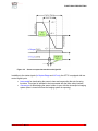
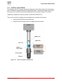
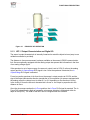
FUNCTIONAL DESCRIPTION
Figure 2-1
PRINCIPLE OF OPERATION
2.1.3 ATF- 5 Output Characteristics and Digital I/O
The sensor’s output characteristic is internally linearized to match the objective lens (easy to use
calibration software is provided).
The distance to focus measurement is always available on the sensor’s RS232 communication
link. Sensors optionally equipped with the analog output also present this information in the form
of an analog voltage signal.
If the specimen is out of sensor range, the sensor’s output is set to 0 DU (5 volts on the analog
output) and the In Capture Range DI/O signal is low. Once the specimen is detected, the In
Capture Range DI/O signal is asserted.
For as long as the specimen is far from focus, the sensor’s output remains at 512 DU and the
sign of the output indicates the direction towards the In Focus position (for sensors equipped with
the analog output the voltage is set to either 8 V or 2 V depending on the direction to focus).
In the vicinity of focus the sensor’s characteristic is linear i.e. the output is proportional to the
distance to focus.
Once the microscope reaches the In Focus position, the In Focus DI/O signal is asserted. The In
Focus DI/O signal remains high as long as the microscope objective is maintained within its
depth of field (DOF). The width of the DOF can be configured with the software.
ATFocus-5 User’s Manual
2-3
FUNCTIONAL DESCRIPTION
Figure 2-2
Sensor’s output characteristic and digital I/O
In addition to the status signals (In Capture Range and In Focus), the ATF-5 is equipped with two
control digital inputs:
• Laser enable for deactivating the sensor’s laser and suspending the auto-focusing
functions. This signal is intended to be incorporated with the laser safety interlock.
• Camera sync for deactivating the sensor’s laser in sync with the microscope’s imaging
system (laser is turned off when the imaging system is exposing).
ATFocus-5 User’s Manual
2-4
FUNCTIONAL DESCRIPTION
2.1.4 TYPICAL APPLICATION
For installation, the ATF-5 sensor requires an optical port in the infinity range of the microscope
and a customized mounting bracket for attaching the sensor. The sensor’s output is sent to the
auto-focus servo controller for automatic adjustment the microscope objective “Z” position.
If application assistance is required, please contact WEGU-DEVICE Inc.
There are two options to interface a user supplied servo-controller to the sensor:
•
using a serial (RS232) communication link,
•
using the sensor's analog output and digital inputs and outputs
Figure 2-3
Auto Focus System Components
ATFocus-5 User’s Manual
2-5