1
USB CAN bus
User Manual V1.2
USB CAN bus
User Manual V1.2
Revision History
Rev
Date
Note
Author
1.0
June 25, 2010
1. Initial draft
Bruce
User Manual
1.1
Sept. 24, 2010
1. Revise for Hardware Spec
Bruce
UCAN Board
1.2
Nov, 10, 2010
1. Add Windows SDK
Bruce
USB CAN bus
User Guide Revision 1.2
Page 1
Page 2
USB CAN bus
User Manual V1.2
USB CAN bus
User Manual V1.2
Index
Chapter 1 Product Overview................................................................. 5
CHAPTER
1.1
Required Properties at a glance ............................................... 5
1.2 Hardware Specification ......................................................................... 6
Chapter 2 WIN-CAN Driver and AP Installation .................................... 10
2.1
2.2
2.3
Connection to the PC............................................................ 10
CAN Bus Driver Installation ................................................... 10
WIN-CAN Software Setup...................................................... 13
Chapter 3 WIN CAN Software Quick Start Guide .................................. 16
1
3.1 WIN-CAN Software Overview .............................................................. 16
Chapter 4 CAN bus Windows SDK API Specification ............................. 21
4.1 Define Documentation........................................................................ 21
4.2 Function Documentation..................................................................... 22
WIN-CAN USB CAN bus Product Overview
Chapter5 CAN bus Linux SDK API Specification .................................... 30
This chapter contains general information that will be useful
to know before using the UCAN CAN bus Board and the details
about the USB CAN bus hardware utility
5.1 Linux Driver Installation ...................................................................... 30
5.2 Define Documentation........................................................................ 31
Page 3
Page 4
USB CAN bus
User Manual V1.2
Chapter 1 Product Overview
USB CAN bus
User Manual V1.2
1.2 Hardware Specification
This chapter provides an overview of the UCAN CAN bus Board, which can be
connected with the PC to create a simple two mode Controller Area Network (CAN)
bus and it can be controlled or monitored via the PC interface.
Using the PC interface, user can configure the UCAN board registers; send CAN
bus and receive CAN messages. This board is using the USB interface to connect
with Windows or Linux OS Compatible PC. It is also suitable for use with laptop
computers.
Any PC can be linked to CAN bus network through this unit. With the
so-called isolation version of the USB CAN adapter which can tolerates up to 2500V
galvanic between the PCs.
UCAN board is equipped with Philips SJA1000 chips which are designed
for use as the USB CAN bus application. The UCAN board delivers the baud
rate up to 1M/bits per second as its data transferring speed.
CAN bus Data Transfer
bi-directional transmission speeds
(Packages/Sec)
Simplex
Transfer(send or receive only)
3800
Duplex
Transfer(send and receive
simultaneously)
1000
bi-directional
Table 1-1
CAN bus Data Transfer speed
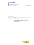
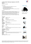
Diagram 1.1 USB CAN bus Utility
1.1 Required Properties at a glance
Connection of a High-speed CAN (CAN specification 2.0A and 2.0B) to a PC
Use of USB port at the PC (Prefer with USB 2.0 compatible)
For 1M/bps High bit rate
Power supply via USB connection
Equipped with the CAN controller SJA1000 by Philips
CAN bus transfers rate up to 1MB bit/s
CAN bus connection 9-pin D-Sub male, pin assignment by CiA
Recommendation DS102
Galvanic isolation at CAN bus connection up to 2500V
Support for operating system Windows (2000 SP4, XP, Vista, Vista 64 bit,
Windows 7, Windows 7 64 bit) and Linux
Page 5
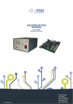
Figure 1-1 UCAN Board Top View
Figure 1-2 UCAN Board 45-degree angle view
Page 6
USB CAN bus
User Manual V1.2
USB CAN bus
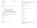
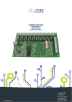
CAN bus Hardware Pin Definition
J3
: CAN BUS Output
Pin No.
Symbol
1
CAN1-H
2
CAN1-L
3
GND
4
CAN2-H
5
CAN2-L
6
GND
Figure 1-3 UCAN Board Dimension
USB1
Figure 1-4 UCAN Board CAN BUS I/O Port Pin Definition
Symbol
2
VCC
4
USB -
6
USB +
8
GND
1
VCC
3
USB -
5
USB +
7
GND
120Ω
2 Short 3
Normal
:
120Ω
1
2
3
Functions
1 Short 2
JP5
1
3
2
4
: terminator resistor
Pin No.
terminator resistor
Pin No.
Page 7
:USB PIN HEADER
Pin No.
JP2
User Manual V1.2
Functions
1 Short 2
120Ω
2 Short 3
Normal
Page 8
Normal
1
2
3
USB CAN bus
User Manual V1.2
USB CAN bus
User Manual V1.2
Chapter 2 WIN-CAN Driver and AP Installation
2.1
Connection to the PC
CHAPTER
We recommend that you set up the driver before connecting the WIN-CAN USB
CAN bus module to the PC for the first time. Please follow the following steps to set
up the driver.
2.2 CAN Bus Driver Installation
2
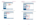
Step1: Insert the USB CAN bus driver CD that comes with the accessories into the
PC’s CD-ROM. Open the file folder named “Windows AP”
Win-CAN Driver & AP Installations
This chapter provides how to install the CAN bus driver and software
installations
.
Page 9
Page 10
USB CAN bus
User Manual V1.2
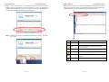
Step2: Double click the “Drivers” folder then proceed.
USB CAN bus
User Manual V1.2
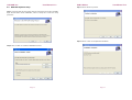
Step4: Select “ftdbus.inf” and click right button of mouse, and then click “install” to
proceed.
Step3: Double click the “CDM 2.06.00 WHQL Certified” folder then proceed.
Step5: Select “ftdport.inf” and click right button of mouse, and then click “install” to
finish the installation.
Page 11
Page 12
USB CAN bus
User Manual V1.2
2.3 WIN-CAN Software Setup
USB CAN bus
User Manual V1.2
Step 3: Click on “Next“ to proceed.
Step 1: Insert the Driver CD that comes with the accessories into the PC’s CD-ROM.
Open the file folder named “WIN-CAN”, Click on “Setup.msi” to start the setup
procedure.
Step 4: Click on “close“ to complete the installation.
Step 2: Click on “Next“ to install the USB CAN bus’ driver.
Page 13
Page 14
USB CAN bus
User Manual V1.2
USB CAN bus
User Manual V1.2
Chapter 3 WIN CAN Software Quick Start Guide
3.1 WIN-CAN Software Overview
Program Start
CHAPTER
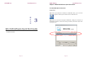
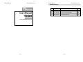
Step 1: After you finished the installation of “WIN-CAN” driver, you can find the
icon of this program as follows, please double click the” WIN-CAN” icon.
3
Step 2: After you executed the program of WIN-CAN, a dialog for the selection of
the CAN bus hardware as well as the setting of CAN bus parameters appear after
the program start.
Win CAN Software Quick Start Guide
This chapter describes how to use the WIN-CAN software and Technical Spec
of CAN bus Hardware.
Page 15
Page 16
USB CAN bus
User Manual V1.2
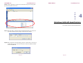
Step 3: There are “Standard” and “Extended” mode of ID information. As the
Standard mode, the parameters set up from “0 x000” to “0x 7FF” by hexadecimal
numbers. And the Extended mode, the parameters set up from” 0x 00000000” to
“ 0 x 1FFFFFFF” also by the hexadecimal calculating ways.
USB CAN bus
User Manual V1.2
Step 5: After you click the “Run” button, the WIN-CAN Transmit/Receive window
will pop up as follows: The icons are the hot keys for setting on the top left corner
of the window, it is the user-friendly interface to people to operate.
,
Step 4: The Baud Rate speed can be adjusted from 50 kBit/s to 1Bit/s then click”
Run”. button
Icon
Page 17
Name
Function
Connect
It disconnects current device and reselect it again.
Reset
It makes hardware reset and clear receive and
transmit window.
New
It adds a new transmit package.
Exit
It exits the WIN-CAN program
Get State Info
It shows the mode and baud rate of the current
setting
About
It shows the version of the software
Page 18
USB CAN bus
User Manual V1.2
USB CAN bus
User Manual V1.2
CHAPTER
Step 6: Click the right button of mouse on the transmit zone, you can set up/ edit
the new transmit data in this zone.
4
Windows SDK API Specification
This chapter shows the Windows SDK API Code
Step 7: After click “New”, it will pop up the new message window. You need to set
up the ID information (Hex), Length, and Data into the settings.
Step 8: After you finish the new data setting, click the “Transfer Rate”, it will pop up
Transfer Rate, you can choose mini seconds or select full speed to transfer
the data by WIN-CAN.
Page 19
Page 20
USB CAN bus
User Manual V1.2
Chapter 4 CAN bus Windows SDK API Specification
USB CAN bus
User Manual V1.2
4.2 Function Documentation
4.2.1 FTDI .FT_STATUS _WM_OPEN(uint DeviceNo);
4.1 Define Documentation
// All kinds of transmitting rate.
enum BaudRate{
BR_20KBPS = 0,
BR_40KBPS = 1,
BR_50KBPS = 2,
BR_80KBPS = 3,
BR_100KBPS = 4,
BR_125KBPS = 5,
BR_200KBPS = 6,
BR_250KBPS = 7,
BR_400KBPS = 8,
BR_500KBPS = 9,
BR_666KBPS = 10,
BR_800KBPS = 11,
BR_1000KBPS = 12,
Description:
Open by device index.
Parameters:
DeviceNo [IN]:
If it exist two devices, device will be assigned index ‘0’ and ‘1’ respectively.
Type: uint
Ex :
using CanbusSDK;
using FTD2XX_NET;
…
canbus WinCan = new canbus();
if(WinCan._WM_OPEN(0) = = FTDI.FT_STATUS.FT_OK){
// Open the first plugged in device successfully }
or
}
if(WinCan ._WM_OPEN(1) = = FTDI.FT_STATUS.FT_OK){
// Open the second plugged in device successfully
}
Returns:
FTDI.FT_STATUS.FT_OK if successful, otherwise the return value is FTDI.FT_STATUS
error code.
Page 21
Page 22
USB CAN bus
User Manual V1.2
4.2.2
FTDI .FT_STATUS _WM_INIT(byte[ ] bDeviceID, byte bBRateIndex,
byte[ ] bAcceptMask, byte bMode);
USB CAN bus
User Manual V1.2
WinCan
Convert.ToByte(Canbus.BaudRate.BR_1000KBPS), bMask, 1);
._WM_INIT(bID,
Returns:
Description:
FTDI.FT_STATUS.FT_OK if successful, otherwise the return value is FTDI.FT_STATUS
Specify and initial the opened device.
error code.
Parameters:
bDeviceID [IN]:
Set opened device ID as
0x00000000~0x1FFFFFFF (Extended Mode).
Type: byte array.
0x00~0x7FF
(Standard
Mode)
or
bBRateIndex [IN]:
4.2.3
FTDI .FT_STATUS _WM_WriteOnePacket(byte[ ] bID, byte bLen,
byte[ ] writebuf);
Description:
Set transmitting rate
Type: byte
Write data with this ID header via opened device.
bAcceptMask [IN]:
It is defined as a filter, and it determines to receive any corresponding ID
sending data.
Type: byte array
Parameters:
bID [IN]:
Set ID header for writing packet to wanted device.
Type: byte array.
bLen [IN]:
Length of data to be wrote (0 - 8).
Type: byte.
writebuf [IN]:
Written Data.
Type: byte array
X : don’t care.
The identifier consist of 11 bits ( ID 10 is most significant bit). Only ID.3 – ID.10 can be set. At
the bit
positions containing a “1” in the mask, any value is allowed in the composition of the identifier.
The same is
valid for the three least significant bits.
Returns:
FTDI.FT_STATUS.FT_OK if successful, otherwise the return value is FTDI.FT_STATUS
error code.
bMode [IN]:
It is defined as a different mode.
Mode 0 : Standard Mode
Mode 1 : Extended Mode
Type: byte
Ex :
byte[] bID = new byte[4]; bID[0] = 0x1F; bID[1] = 0xFF; bID[2] = 0xFF;
bID[3] = 0xFF;
byte[] bMask = new byte[4]; bMask[0] = 0xFF; bMask[1] = 0xFF;
bMask[2] = 0xFF; bMask[3] = 0xFF;
Page 23
Page 24
USB CAN bus
User Manual V1.2
4.2.4
FTDI .FT_STATUS _WM_WriteMultiPackets(int level, byte[ , ] _id,
byte[ , ] _datalen, byte[ , ] _data);
USB CAN bus
User Manual V1.2
4.2.5
FTDI.FT_STATUS _WM_ReadPacket(ref byte[ ] bID, ref byte bLen,
byte[ ] readbuf, ref int busheavy, ref int mode);
Description:
Description:
Write all data with different ID headers at the same time via opened device.
Parameters:
Read data via opened device.
Parameters:
level [IN]:
ID [OUT]:
It shows numbers of IDs to be written.
Type: int.
_id [IN]:
Read data with this ID header via opened device.
Type: ref byte array.
bLen [OUT]:
Write all data with different ID headers sequentially.
Type: byte array of two dimensions.
_datalen [IN]:
Received data length.
Type: ref byte.
readbuf [OUT]:
Set every data length (0 - 8) sequentially to be written.
Type: byte array of two dimensions.
_data [IN]:
Received data.
Type: byte array
Busheavy[OUT]:
All Written Data.
Type: byte array of two dimensions.
If signal ocurrs some error to result in device not to work ,it will return false.
Type: ref int.
mode[OUT]:
EX:
byte[,] id = new byte[2, 4];
byte[,] datalen = new byte[2, 1];
byte[,] data = new byte[2, 8];
int i = 0;
for (int i = 0;i < 2;i++) {
id[i, 0] = i;
id[i, 1] = 0xFF;
id[i, 2] = 0xFF;
id[i, 3] = 0xFF;
datalen[i, 0] = 8;
for (int j = 0; j < 8; j++)
{ data[i, j] = j; }
}
FTDI.FT_STATUS ftStatus = cb._WM_WriteMultiPackets(i, id, datalen,
data);
It show that the data format is standard or extended mode.
Type: ref int.
EX:
byte[] ID = new byte[4];
byte Len = 0;
int status = 0;
int mode = 0;
byte[] receivedata = new byte[8];
WinCan ._WM_ReadPacket(ref ID, ref Len, receivedata, ref status, ref
mode);
Returns:
FTDI.FT_STATUS.FT_OK if successful, otherwise the return value is FTDI.FT_STATUS
error code.
Returns:
FTDI.FT_STATUS.FT_OK if successful, otherwise the return value is FTDI.FT_STATUS
error code.
Page 25
Page 26
USB CAN bus
User Manual V1.2
4.2.6
FTDI.FT_STATUS _WM_GET_STATE(ref int Mode, ref int BaudRate,
ref int ErrorCode, ref int ErrorLimit, ref int RxError, ref int TxError);
USB CAN bus
4.2.7
FTDI .FT_STATUS _WM_PURGE();
User Manual V1.2
Description:
Description:
It uses to purge the Tx and Rx buffer.
Get bus status.
Returns:
Parameters:
FTDI.FT_STATUS.FT_OK if successful, otherwise the return value is FTDI.FT_STATUS
Mode [OUT]:
error code.
It shows current executing mode.
Type: ref int.
BaudRate [OUT]:
4.2.8
It shows current executing transmitting rate
Type: ref int.
ErrorCode [OUT]:
It shows current executing error code.
Type: ref int.
ErrorLimit [OUT]:
It shows current executing error limit
Type: ref int.
RxError [OUT]:
It shows current executing RX error
Type: ref int.
TxError [OUT]:
It shows current executing TX error
Type: ref int.
FTDI .FT_STATUS _WM_HW_RESET();
Description:
When the device isn’t working, you need to reset the device to make sure that it could
keep on working.
Returns:
FTDI.FT_STATUS.FT_OK if successful, otherwise the return value is FTDI.FT_STATUS
error code.
4.2.9
FTDI .FT_STATUS _WM_CLOSE();
Description:
Close the opened device.
Returns:
FTDI.FT_STATUS.FT_OK if successful, otherwise the return value is FTDI.FT_STATUS
Returns:
FTDI.FT_STATUS.FT_OK if successful, otherwise the return value is FTDI.FT_STATUS
error code.
error code.
Page 27
Page 28
USB CAN bus
User Manual V1.2
USB CAN bus
User Manual V1.2
Chapter5 CAN bus Linux SDK API Specification
5.1 Linux Driver Installation
1. unzip and untar the file given to a suitable directory
CHAPTER
gunzip libftd2xx0.4.13.tar.gz
5
Linux SDK API Specification
tar -xvf libftd2xx0.4.13.tar
2. As root user copy the following files to /usr/local/lib
cp libftd2xx.so.0.4.13 /usr/local/lib
3. Change directory to /usr/local/lib
cd /usr/local/lib
This chapter shows the Linux SDK API Code
4. make symbolic links to these files using the following
commands:
ln -s libftd2xx.so.0.4.13 libftd2xx.so
5. Change directory to /usr/lib
cd /usr/lib
6. make symbolic links to these files using the following
commands:
ln -s /usr/local/lib/libftd2xx.so.0.4.13 libftd2xx.so
Page 29
Page 30
USB CAN bus
7. Add the following line to /etc/fstab:
User Manual V1.2
USB CAN bus
_WM_SETID_ERROR,
none /proc/bus/usb usbdevfs defaults,devmode=0666 0
User Manual V1.2
_WM_SETMASK_ERROR,
0
_WM_SETBAUDRATE_ERROR
There have been reports that you may need to use the following
}; //Return current status.
command for some distros
#define BYTE unsigned char
none /proc/bus/usb usbdevfs defaults,mode=0666 0 0 (use usbfs in
#define DWORD unsigned long
2.6 kernels)
enum DEVICE_USB_CAN
{
8. Remount all in the fstab file
USB_CAN1 =0,
mount -a
USB_CAN2 =1
}; //Support two deivces.
9. Copy the following files to /usr/lib
cp -f
libWCan.so
struct _CBUS_STRUCT
/usr/lib
If you have problems with this check with usbview
file system is mounted properly.
{
to check the usb
FT_HANDLE ftHandle[2];
}CBUS_STRU[2];
enum Baudrate
{
BR_20KBPS = 0,
BR_40KBPS = 1,
BR_50KBPS = 2,
BR_80KBPS = 3,
BR_100KBPS = 4,
BR_125KBPS = 5,
BR_200KBPS = 6,
BR_250KBPS = 7,
BR_400KBPS = 8,
BR_500KBPS = 9,
BR_666KBPS = 10,
BR_800KBPS = 11,
5.2 Define Documentation
enum {
_WM_OK,
_WM_ERROR,
_WM_OPEN_ERROR,
_WM_WRITE_ERROR,
_WM_READ_ERROR,
_WM_CLOSE_ERROR,
Page 31
Page 32
USB CAN bus
User Manual V1.2
USB CAN bus
User Manual V1.2
Close device by choosing device index.
BR_1000KBPS = 12
}; //Baudrate Setting.
Parameters:
dev [IN]:
5.3 Function Documentation
Description : Device index.
5.3.1 int _WM_OPEN (enum DEVICE_USB_CAN dev)
Description:
Type : enum DEVICE_USB_CAN
Ex :
if(_WM_Close (USB_CAN1) == _WM_OK)
Open device by choosing device index.
{
//Close “USB_CAN1” successfully.
}
or
if(_WM_Close (USB_CAN2) == _WM_OK)
{
//Close “USB_CAN2” successfully.
}
Parameters:
dev [IN]:
Description : Device index.
Type : enum DEVICE_USB_CAN.
Returns:
Ex :
if(_WM_OPEN (USB_CAN1) == _WM_OK)
_WM_OK if successful, otherwise the return value is an error code.
{
//Open “USB_CAN1” successfully.
}
or
if(_WM_OPEN (USB_CAN2) == _WM_OK)
{
//Open “USB_CAN2” successfully.
}
5.3.3 int _WM_INIT (BYTE *bDeviceID, BYTE bBRateIndex, BYTE
*bAcceptMask, BYTE bMode,enum DEVICE_USB_CAN dev)
Description:
Returns:
Initial the opened device.
_WM_OK if successful, otherwise the return value is an error code.
Parameters:
5.3.2 int _WM_Close (enum DEVICE_USB_CAN dev)
bAcceptID[ ] [IN]:
Description:
Description: Set opened device ID (0x00~0xFF).
Type: BYTE Point
Page 33
Page 34
USB CAN bus
User Manual V1.2
USB CAN bus
User Manual V1.2
bBRateIndex [IN]:
_WM_OK if successful, otherwise the return value is an error code.
Description: Set transmitting rate
5.3.4 int _WM_WriteOnePacket(BYTE*
writebuf,enum DEVICE_USB_CAN dev)
Type: BYTE
bID,
BYTE
bLen,
BYTE*
Description:
bAcceptMask[ ] [IN]:
Write data with this ID header via opened device.
Description: It’s defined as a filter, and it determines to receive any corresponding sending
data.
Parameters:
Type: BYTE Point
bID [IN]:
Description: Write data with this ID (0x00~0xFF) header to wanted device.
Type: BYTE Point
bLen [IN]:
Length of data to be wrote (0 - 8).
X : don’t care.
The identifier consist of 11 bits ( ID 10 is most significant bit). Only ID.3 – ID.10 can be set. At
the bit
positions containing a “1” in the mask, any value is allowed in the composition of the identifier.
The same is
valid for the three least significant bits.
Type: BYTE
writebuf [IN]:
Description: Written Data.
Type: BYTE Point
bMode[ ] [IN]:
dev [IN]:
Description: 0 : Standard Mode,1 : Extended Mode.
Description : Device index.
Type: BYTE
Type : enum DEVICE_USB_CAN
dev [IN]:
Returns:
Description : Device index.
Type : enum DEVICE_USB_CAN
_WM_OK if successful, otherwise the return value is an error code.
5.3.5 int _WM_WriteMultiPackets(int level, BYTE* _id, BYTE* _datalen,
BYTE* _data,
enum DEVICE_USB_CAN dev);
Returns:
Page 35
Page 36
USB CAN bus
User Manual V1.2
Description:
USB CAN bus
User Manual V1.2
5.3.6 int _WM_ReadPacket(BYTE* bID, BYTE* bLen, BYTE* readbuf, int*
busheavy, int* mode,enum DEVICE_USB_CAN dev);
Write different data with different ID header via opened device at the same time.
Description:
Parameters:
Read data via opened device.
level [IN]:
Parameters:
Description: It presents how many data sets to write.
bID [OUT]:
Type: int
Description: Read data with this ID header via opened device.
_id [IN]:
Type: BYTE Point
Description: Write data with this ID (0x00~0xFF) header to wanted device.
bLen [OUT]:
Type: BYTE Point
Description: Received data length.
_datalen[IN]:
Type: BYTE Point
Description: Length of data to be wrote (0 - 8).
readbuf [OUT]:
Type: BYTE Point
Description: Received data.
_data[IN]:
Type: BYTE Point
Description: Written Data.
busheavy[OUT]:
Type: BYTE Point
Description: If signal ocurrs some error to result in device not to work ,it will return non-zero
value.
dev [IN]:
Type: int Point
Description: Device index.
mode[IN]:
Type: enum DEVICE_USB_CAN
Description: Get current mode.
Returns:
_WM_OK if successful, otherwise the return value is an error code.
Page 37
Type: int Point
Page 38
USB CAN bus
User Manual V1.2
USB CAN bus
dev [IN]:
dev [IN]:
Description: Device index.
Description: Device index.
Type: enum DEVICE_USB_CAN
Type: enum DEVICE_USB_CAN
User Manual V1.2
Returns:
Returns:
_WM_OK if successful, otherwise the return value is an error code.
_WM_OK if successful, otherwise the return value is an error code
5.3.7
int _WM_HW_RESET(enum DEVICE_USB_CAN dev);
Description:
Hardware Reset Function.
Parameters:
dev [IN]:
Description: Device index.
Type: enum DEVICE_USB_CAN
Returns:
_WM_OK if successful, otherwise the return value is an error code
5.3.8
int _WM_SW_RESET(enum DEVICE_USB_CAN dev);
Description:
Software Reset Function.
Parameters:
Page 39
Page 40