1
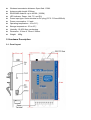
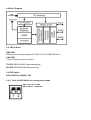
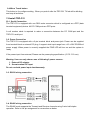
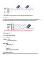
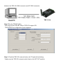
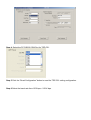
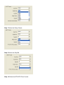
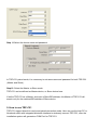
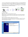
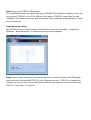
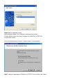
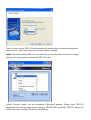
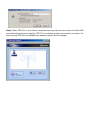
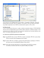
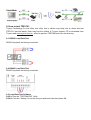
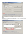
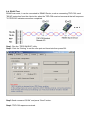
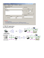
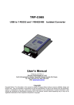
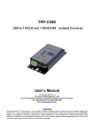
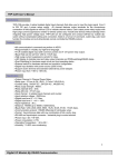
TRP-C51 Version:B Bluetooth to RS232/422/485 Converter User’s Manual Printed Sep. 2015 Rev 1.2 Trycom Technology Co.,Ltd No.35, Zhongxing Rd., Guishan Township, Taoyuan County 333, Taiwan. Tel : 886-3-350-3351 Fax: 886-3-350-3352 Web: www.trycom.com.tw Copyright Copyright Notice: The information in this manual is subject to change without notice to improve reliability, design and function and does not represent a commitment on the part manufacturer. No part of this manual may be reproduced, copied, or transmitted in any form, without prior written permission by the manufacturer. Products mentioned in this manual are mentioned for identification purposes only. In this manual, product names appearing may or may not be registered trademarks of their respective companies or copyright. 1.Introduction The TRP-C51 is high stability device that is able to re-connect when the external power fail in paired mode, it provides a simple and friendly interface that allows user easy to configure the serial data format. Based on the 2.4g automatic frequency hopping technology, It is widely used in parking towers, industrial automation, moving rail cars and .. etc. TRP-C51 can operate in direct link mode and paired mode, when in paired mode, the user just need to power two devices, and they will automatically connect. 1-1.Features Bluetooth V1.2 Class 1 compliance. (2.5mW/4dBm) Transmission range open filed over to 100M. Auto reconnect when the external power lost. Auto clear serial buffer when the data continuity input when re-boot. Auto directionally RS485 signal communication. Option to 1KM when replace the direction antenna. Support all common baud rate from 1.2K to 256Kbps. Friendly interface TRP-BT configuration windows utility RS422 and RS485 signal auto switching. LED indicators for Power/Link/TX/RX. Surge protection on RS422/RS485. Power supply: Screw terminal, or external DC adapter. Wide input range power supply. DIN rail and panel mount support. 1.-2.Specifications Power requirement: DC voltage input from +10V to +30V. RS232 signal: TXD, RXD, GND, RTS, CTS. RS422/485 connection: industrial plug-in screw terminal. RS485 signal: differential 2 half-duplex wires. (D+, D-) RS422 signal: differential 4 full-duplex wires.(TX+, TX-, RX+, RX-) Baud rate: 1.2Kbps to 256Kbps. Data bit: 8 Support Parity check: None, Even, Odd. Stop bit: 1, 2. RS232 flow control RTS/CTS: Enable, Disable. Host PC com port to TRP-C51 connection: use null modem female-female cable. Plug-in screw terminal wiring: Accepts AWG #12 ~30 wires. Wireless transmission distance: Open filed: 100M. Antenna cable length:1530mm. RS422/485 distance: up to 4000ft. (1200M) LED indicator: Power, Link, TX, and RX. Power input type: Screw terminal or DC plug.(5.5*2.1*12mm/500mA) Power consumption: 1.2 watt. Operating temperature: -10 to 50℃. Storage temperature: -20 to 65℃. Humidity: 10-90% Non-condensing. Dimension: 151mm X 75mm X 26mm. Weight: 400g. 2. Hardware Description 2-1. Panel layout 2-2.Block Diagram 2-3. LED Indictor PWR LED: When power is properly supplied to TRP-C51, the PWR LED will on. LINK LED: Turn on: Device connects availed. TX LED: RS232/422/485 data transmitting. RX LED: RS232/422/485 data receiving. 2-4. DIP Switch Select RS232 or RS422 / 485 2-4-1. The 2-Pin DIP-Switch for configuration mode SW1,2: OFF OFF: RS232 SW1,2:ON ON: RS422/485 2-4 Micro Touch button This button is for configure setting . When you push it after the TRP-C51 TX led will be blinking and stop all activities. 13.Install TRP-C51 23-1. Serial Connection The TRP-C51 is equipped with one DB-9 male connector which is configured as a DTE (data terminal equipment) device. All PC COM ports are DTE ports. A null modem cable is required to make a connection between the PC COM port and the TRP-C51 serial port. 3-2. Power Connection The TRP-C51 is equipped with a 2-pin terminal block and power jack. Power can be supplied from terminal block or external DC plug. It support wide input range from +10~+30V DC/500mA power supply. When power is correctly supplied the PWR LED will turn on and the system is ready. If the power input from external, Please use the power plug specification. (5.5*2.1*12 mm). Warning: User can only choose one of following 2 power sources. 1. External DC adapter. 2. Screw terminal DC input Do not use both power input simultaneously. 3-3. RS232 wiring connection 3-4. RS485 wiring connection The RS485 mode supports the Transmit and Receive channels using 2-wire half-duplex operation. Refer to the pin assignment for connection as below. *The RTS/CTS must be disable if the user using the RS422/485 function. 3-5. RS422 wiring connection The RS422 mode supports 4 channels with full duplex operation for Receive and Transmit, The data lines are in differential pairs. Refer to the pin assignment for connection as below. *The RTS/CTS must be disable if the user using the RS422/485 function. 4. Getting start 4-1.TRP-C51 default Settings Bluetooth Status Name: TRP-C51 Password: 1234 Connection Mode: Slave Device: Discoverable UART Status Baud Rate: 9600 Data Bit: 8 Parity Check: None Stop Bit: 1 RTS/CTS Flow Control: Disable 4-2. Configure TRP-C51 Step1. Use a Null modem cable (crossover female to female cable) to make a connection between the TRP-C51 DB-9 connector and PC DB-9 connector. Step.2 Run the TRP-BT Utility. *User may find the TRP-BT utility in TRP-C51 support CD. TRP-BT.EXE the configuration screen appears. Step.3. Push the TRP-C51 external button, the TX light will be blinking. * Make sure the TRP-C51 external switch fixed on the OFF OFF position. Step.4. Select the PC RS232 COM Port for TRP-C51. Step.5 Click the “Read Configuration” button to read the TRP-C51 setting configuration. Step.6 Select the baud rate from 1200 bps ~ 256 K bps. Step 7 Select the Parity Check. Step 9 Select the Stop Bit. Step 10 Select the RTS/CTS Flow Control. Step 11 Select the device name and password. In TRP-C51 paired mode, it is necessary to set same name and password for both TRP-C51 (Master and Slave) . Step12. Select the Master or Slave mode. TRP-C51 can be defined as Master device, or Slave device here. If define TRP-C51 as a Master, and input a Slave BD address, this Master of TRP-C51 will search only for the matched BD address of Slave device. 5. How to use TRP-C51 TRP-C51 support direct link mode and paired connection mode. User can use the host PC or Notebook which with integrated bluetooth interface to wirelessly connect TRP-C51, after the installation system will generate a COM Port for TRP-C51. *If host- PC or Notebook does not equip with Bluetooth interface, you need to add USB dongle as the connection interface. The approved USB dongle is Ergotech type ET-BD121 that is an optional accessory for TRP-C51; however TRP-C51 is compatible with most of USB dongle in the market. User may use own USB dongle for Bluetooth interface. In the next TRP-C51 operating descriptions we use ET-BD121 as example. . 5-1. Direct link mode Step1 Power on TRP-C51 and select TRP-C51 as slave. TRP-C51 accepts + 10~30V DC/500mA power supply. When power is correctly supplied the PWR LED will start lighting, the system is up and discoverable. Use TRP-BT utility to select TRP-C51 as slave. Step.2 Install Bluetooth ET-BD121 USB dongle driver and utility. User may find ET-BD121 USB dongle driver and utility it the ET-BD121 support CD. Insert the CD in the CD drive on the PC the driver CD will auto run. The following InstallShield screen appears. Press “Next > “to continue Step3 Plug in the ET-BD121 USB dongle The InstallShield Wizard will request user plug in ET-BD121D3 during the installation, then user must plug in ET-BD121 on the PC’s USB port. After plug in ET-BD121, press “Next” to start installation. The whole process will take few minutes, when installation completed press “Finish” to end the process. Step4 Bluetooth setting After ET-BD121 driver installed, back to the Windows screen and Click Start – Program file – Bluetooth – Bluetooth setting. The Bluetooth settings screen appears. Step5 Click on “New connection “icon into the Add New Connection Wizard, the USB dongle start to search all discoverable TRP-C51 units. Suppose just only 1 TRP-C51 unit need to be installed, we can see there is only one Bluetooth device been searched with the device name TRP-C51. Click “Next>” to continue. Step6 Select installation mode. Select Express Mode: The COM port is assigned by system. Custom Mode: Allow user freely to assign the COM Port to TRP-C51 Confirm with “Next>” In the next description we select “Custom mode” for explanation. Step7: Assign a appropriate COM port for TRP-C51 and confirm with “Next>”. “Auto Connect” means TRP-C51 will automatically connect when encounters unexpected disconnection.” User may choose the function enable or disable. Step8: Select the installed TRP-C51 icon and click mouse right button to check or change options. User may rename or delete the TRP-C51 here. Select “Connect” option you are requested a Bluetooth passkey. Please Input TRP-C51 password which must be same as the setting by TRP-BT utility, press OK, TRP-C51 will go into searching mode, the LINK LED start to fast blinking. Step9: When TRP-C51 is successfully connected user may see the next screen, the LINK LED stop fast blinking and turn to lighting. TRP-C51 is available to data communication or control. You also may find TRP-C51 has already been added in system device manager. User may back to the Windows screen and Click Start – Program file – Bluetooth – Bluetooth setting to start the second TRP-C51 installation. The number of TRP-C51 that a Host system may install is depended on the COM Port number that the system or OS can offer. 5-2. Paired mode TRP-C51 paired mode allows user to make a wireless connection between 2 RS232/422/485 devices or PLC (Programmable Logic Controller) without hardware or software changes. In this mode the data line signal and data format can be auto detected and converted between each other. The communicating range can up to 100M. 4-3. How to set up TRP-C51 paired connection mode Step.1: Use TRP-BT utility to set one TRP-C51 as master, and another TRP-C51 as slave. Both TRP-C51 devices name and password must be same. Step.2: If define TRP-C51 as a Master, and input a Slave BD address, this Master of TRP-C51 will search only for the matched BD address of Slave device. Step.3: When both units LINK LED become constant lighting, both TRPC51 had been successfully connected each other, the system is ready and workable. 6. How to test TRP-C51 Trycom Technology Co.,Ltd offers test utility, this is utilities may help user to demo and test TRP-C51 fast and easily. User may find the utilities in Trycom support CD or download from Trycom web www.trycom.com.tw , direct to perform TRPCOM.exe from the directory. 6-1.RS232 Loop Back Test RS232 loop back test wiring connection. 6-2.RS422 Loop Back Test RS422 loop back test wiring connection. 6-3.Loop Back Test Software STEP1: Run the “TRPCOM.EXE” utility. STEP2: Click the “Setting” to set the com port and baud rate then press OK . *Please note: “COM2” is an example of COM port number; the real COM number is assigned by user PC. STEP3:. Click the "Terminal" then select Loop back enable, the counter value and pass value will be synchronized counts. 6-4. RS485 Test RS485 test mode, it can be connected to RS485 Device, such as connecting TRP-C28, send "$01M" instruction from the client side, when the TRP-C28 received command that will response "!01TRPC28" indicates execution completed. Step1. Run the “TRPCOM.EXE” utility. Step2. Click the “Setting” to set the com port and baud rate then press OK. Step3.Send command “$01M” and press “Send” button. Step4. TRP-C28 response received. 5. TRP-C51 Application.