1
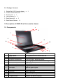
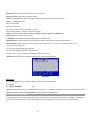
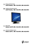
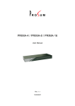
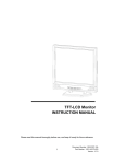
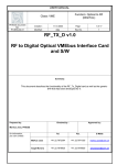
Single Rail LCD Console With 8/ 16 ports KVM User’s Manual Index 1. INTRODUCTION…………………………………………………………………………………………….2 1.1 OVERVIEW …………………….…..………………………………….………………………… ………2 1.2 FEATURES………… …………………………………...……………..………………………………….2 2. SPECIFICATIONS…………………………………………………… …………………………………….3 2.1 GENERAL……………………………………………………………...…………………………………..3 2.2 PACKAGE CONTENTS………………….……………………..……...…………………………………....4 3. DESCRIPTION OF SINGLE RAIL LCD CONSOLE DRAWER………………………………………………… 4 3.1 COMPONENTS…………………….....................……………..………….………………………………4 3.2 CONNECTION……………………………………………………………………………………………5 4. INSTALLATION……………………………………………………….…….…..………………………..……6 5. MODULARIZED COMPONENTS REPLACEMENT.…….…..…………………………………….………………7 5.1 LCD PANEL MODULE REPLACEMENT…………….………………………………………………..7 5.2 KEYBOARD MODULE REPLACEMENT……………………………………………………….….....8 6. OPERATION……………………………………………………….…….…..………………………….…..9 6.1 OSD MAUN……………...……………..………….…………………………………………………….9 6.2 FIRMWARE UPGRADE..…………..………….…………………………………….…..………………..10 1 1. Introduction Thanks for your purchasing the Single Rail LCD Console. We recommend that you read this manual thoroughly and retain it for future reference. 1.1 Overview The Single Rail LCD Console is an ideal module solution featuring an integrated 17/19-inch TFT LCD color display and ultra-high-quality compact industrial keyboard / touch pad in 1U, rack-mountable format, providing a user-friendly and most reliable operation environment for server administrators. The Console drawer, similar to the front-end Console module, provides flicker-free color images at optimal resolutions, and has an ergonomically designed operation functionalities to maximize user convenience. Installation setup can easily be done by a single person. Simply use the supplied Combo VGA cable set to link the ports to the console ports of your KVM switch, no matter whether your connected port interface be either USB or PS/2. On-Screen Display (OSD) Menu allows straightforward display adjustments. For even more convenience, there are two additional external USB ports for front-end connections with an extra set of USB keyboard and mouse, in addition to the original built-in keyboard/ touch pad. Further, we are also providing modular design for LCD monitor and keyboard / touch pad set to enhance convenience to help in case when one of them happens to be out of order, then new replacement could be implemented immediately without further ado. 1.2 Features The Single Rail LCD Console Drawer features an integrated 17-inch/19-inch LCD panel module and keyboard/touch pad module within an 1U chassis. The unique modular design solution is for easy installation and maintenance. Integrated KVM module with 17” / 19” LCD monitor & Keyboard/touch pad module within 1U chassis Supports Single Rail for independent access to panel and keyboard tray Supports modular design for easy installation and maintenance Supports one extra set of USB keyboard and mouse port via front-end USB ports Complies with EIA RS-310C 19” Rack Mount standard Heavy-Duty Electroplate Steel Supports high resolution up to 1280 x 1024 @ 75Hz Supports Combo KVM module to connect servers/KVM via USB & PS/2 connection 2 2. Specifications 2.1 General 17”/19” LCD Display Modules Keyboard/Touch Pad Module 17"/ 19"- 4CCFL LCD Panel SXGA Resolution up to 1024 x1280@75Hz Pixel pitch:0.264(H)x0.264(V)/ 0.294(H)x0.294(V) 6 language OSD English, Chinese, French ,Japanese ,Spanish, German Backlight lifetime: 50,000 hrs. LCD display automatically shut-off at display angle under 30 degrees. 105- key Keyboard supports Windows function keys, compatible with IBM PC/AT, PS/2 keyboard, Keyboard 6 Language Keyboard typeGermany, English, French, Italian, Spanish, Chinese…(option) Touch pad 1000 points/ inch(40 points/mm)-graphics tablet mode Interface: PS/2 (compatible with Microsoft mouse driver) Switch is compatible with PS/2& USB connector. 4 in1 cable combine with Video, KB/MS (PS/2) and USB. Connector Design Windows 98SE/ME/2000/XP/2003/Vista Server, Linux, Mac OS9/OSX and Sun Microsystems. 4 modes for auto scan: Auto-Scan Interval ALL, Live, EzV (EasyView), EzV + Live. Video: 8/ 16 HDB-15 female PC Connectors KB/MS: PS/2 & USB signal combined 8/16 Port KVM Switch Module- (OPTION) Firmware upgrade Mini USB female connector Operating systems Windows 98SE/ME/2000/XP/2003/Vista Server, supported Linux, Mac OS9/OSX and Sun Microsystems. USB device USB A Type Female x 2 ( each port supports 2A) Computer VGA female x 1 (integrated with PS/2 keyboard& mouse) Connector Power adaptor Universal 100~240V AC input, 12V/ 5A DC output Materials Heavy-duty steel electroplated for chassis Rail slide Dimensions 45 cm( extended length 22cm)- standard 80 cm( extended length 20cm)-option W X D X H : 44x 45(66)x 4.4 cm Dimensions N.W. 10.5 (14.0)KGS/ G.W. 13.5(17.5)KGS 3 2.2 Package Contents 1. 2. 3. 4. 5. 6. Single Rail LCD Console drawer x 1 Custom KVM Cables Set x 1 Power Cord x 1 User’s Manual x 1 Rack Mount Kit x 2 Rack Mount Screw x 8 3. Description of SINGLE rail lcd console drawer 3.1 Components 1 12 2 3 11 13 10 4 5 9 6 7 8 No. Component Function Description 1 2 3 4 5 6 7 8 9 10 11 12 13 Handle Holder LCD Display LCD Panel OSD Buttons LED Indicators Slide Rail x 1 Connection switch USB Ports x 2 (K/B, Mouse) Power LED Power Switch Touch Pad Keyboard Module LCD Lock Screws 8/ 16 ports KVM Pull to Slide the LCD console in or out Panel Display Controls Display Required Quality Switching Operation for KVM Module ( Optional ) Single Slide Rail PS/2 & USB switch Plug-in external K/B and Mouse. Indicates Power Status Turn on / Turn off Mouse Operation Keyboard Operation Fix or Release LCD panel Modular KVM for 8/ 16 ports 4 3.2 Connection. Use the daisy-chain cable (M-HDB15-HDB15-F) to connect the DaisyChain OUT Port (HDB 15 female) of the (master) KVM Switch Module to the DaisyChain IN Port (HDB 15 male) of the second KVM switch. Connect the power cord to the second switch to power it on. Daisy-chain cable Terminator If you have yet another switch to be daisy-chained, just repeat Step 3 to connect them. You can daisy-chain up to 16 units of KVM switches. Plug a terminator onto the Daisy-chain Out Port of the last KVM switch unit. No Terminator is required if only using a single unit. (Now your KVM switch module or daisy-chained KVM Switches should have been powered-up and initialized….) Connect each of your computers to a computer port on the rear of the switch(es). You should use the special USB PS/2 KVM cable (with the USB-to-PS/2 adapter) for connection to a USB computer (PS/2 computer). Special integrated USB & PS/2 KVM cable 5 4. INSTALLATION Precaution: 1. Please check the whole unit for any damaged or missing parts and make sure that power to all the devices you will be connecting to have been turned off. when you received the package. If you encounter any problem, please kindly contact your dealer. Installation Step 1 Install the LCD console on Cabinet. ※ Tighten the screws on the rails. Step 2 Install the KVM module to LCD console by rack mount kits or rack mount screws. ※ screw the box for connection LCD console and KVM Rack Mount Kit X2 or Rack Mount Screw X8 6 5. Modularized Components Replacement 5.1 LCD Panel Module Replacement. Step 1. Turning loose 2 pcs of screws on each side, and then pull to lift it out. Step 2. Apply gentle force to lift the LCD panel module upward. 7 Step 3. Take a new LCD panel and make due downward alignment to the tray chassis so that it can easily be docked with the VGA connector. When you have fit it into the chassis, then try put the screws on both side of the panel and tighten them up. The replacement is now complete. 5.2 Keyboard Module Replacement. Step 1. Remove one screw on each side of the keyboard tray, and then you can pry and pull up the keyboard module to reveal the underside of it. 8 6. OPERATION 6.1 OSD Menu To activate the OSD (On Screen Display) Menu, use the hotkey sequence: Activate OSD = ScrLk + ScrLk + Space Bar Deactivate OSD = ESC (Escape key) Main OSD Menu Main menu Select computer: use Up/Down Arrow key to navigate, PgDn/Up to scroll page to view computers on different banks. Hit Enter to select. Edit computer name: just hit Insert to edit and Enter to confirm. F1 : Next Page - rotate through Main Page / Setup page / Status page F10: Logout - lock your keyboard and mouse for security. Password will be needed to log in. F6: EasyView – Toggle select/de-select the highlighted computer to be included with the EasyView (EzV) scan group (by factory default, all computers are ). Note that the “V” mark between the bank number and PC name is to indicate that it is included within the EzV scan group. Setup Menu Setup Menu Auto logout: specify time for auto logout (00~99 min) 9 OSD timeout: specify duration for OSD menu to stay on screen Autoscan period: specify time for autoscan period Title bar: enalble/disable the title bar, and also specify its position. There are five title bar options: Disable - Disable the title bar Left – Title bar on left Right – Title bar on left Left (Left Timeout) – Title bar on left for 5 seconds Right (Right Timeout) – Title bar on right for 5 seconds Hotkey: specify the hotkey preceding sequence (SCROLL LOCK, CAPS, F12 or NUM LOCK) Password: specify the password for access Load Default: Load default setting to all KVM switches in the daisy-chain. OSD Appearance: Specify whether you want to keep or hide the OSD menu after port switching operation. Autoscan Mode: Select Autoscan modes. There are 4 modes for autoscan: ALL, Live, EzV (EasyView), EzV + Live. ALL – Scan all computer ports Live – Scan all computers with live power feed EzV – Scan all computers joined into the EzV Group EasyView + Live – Scan only those Live computers within the EzV group. F2 Autoscan: Start Autoscan according to the autoscan mode you have specified. Status Menu Status Menu On this page, the KVM system information of each daisy-chained unit will be shown. For example: 01 081216 OSD KVM 08 Mean it’s the first (01) bank of the KVM daisy-chain (can be up to a maximum of16 units), and its firmware version date code is 081216. Model name listed here is OSD KVM, and the port number is eight (08) port. 6.2 Firmware Upgrade This KVM Switch allows its user to upgrade firmware contents whenever is needed to enhance the compatibility to other devices or its functions and performance. For firmware upgrade procedure, please refer to Firmware Upgrade Operation Guide. 10 Disclaimer Information in this document is subject to change without notice. The manufacturer does not make any representations or warranties (implied or otherwise) regarding the accuracy and completeness of this document and shall in no event be liable for any loss of profit or any other commercial damage, including but not limited to special, incidental, consequential, or other damages. No part of this document may be reproduced or transmitted in any form by any means, electronic or mechanical, including photocopying, recording or information recording and retrieval systems without the express written permission of the manufacturer. All brand names and product names used in this document are trademarks, or registered trademarks of their respective holders. FCC Statement This device generates and uses radio frequency and may cause interference to radio and television reception if not installed and used properly. This has been tested and found to comply with the limits of a Class B computing device in accordance with the specifications in Part 15 of the FCC Rules. These specifications are designed to provide reasonable protection against such interference in a residential installation. However, there is no guarantee that interference will not occur in a particular installation. If this device does cause harmful interference to radio or television reception, which can be determined by plugging the device in and out, the user can try to correct the interference by one or more of the following measures: Reorient or relocate the receiving antenna. Increase the separation between the device and receiver. Connect the computer into an outlet on a circuit different from that to which the receiver is connected. Consult the dealer or an experienced radio/TV technician for help. RoHS Compliant 11