1
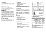
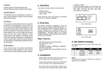
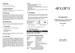
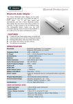
Trademarks 1. Checklist Contents subject to revision without prior notice. The package should contain the following items: All trademarks remain the property of their respective owners. - Media Converter - AC-DC Power Adapter - Quick Installation Guide Copyright Statement This publication may not be reproduced as a whole or in part, in any way whatsoever unless prior consent has been obtained from owner. FCC Warning The Media Converter Series have been tested and found to comply with the limits for a Class A digital device, pursuant to Part 15 of the FCC Rules. These standards are designed to provide reasonable protection against harmful interference when these devices are operated in a commercial environment. These devices generate, use, and can radiate radio frequency energy that may cause harmful interference to radio communications unless installed in accordance with this User’s Guide. Operation of these devices in a residential area is likely to cause harmful interference which will make the user responsible for the appropriate remedial action at his / her own expense. CE Mark Warning These are Class A products. In a domestic environment these products may cause radio interference in which case the user will need to consider adequate preventative methods. This is a lead-free and RoHS-compliant product. Diag Please notify your sales representative immediately if any items are missing or damaged. Figure 1. Media Converter Single-Fiber & SFP Front Panel 2. Overview The Media Converter Series are designed to meet the increasing needs for Gigabit network deployment and are able to extend a copper-based Gigabit network via fiber cable to a maximum distance up to 80KM. The Media Converter Series are fully compliant with IEEE 802.3, 802.3u, 802.3ab & 802.3z standards. It can be installed into a Converter RACK. The installation and operation procedures are simple and straightforward. Operation status can be locally monitored through a set of Diagnostic LED indicators located in the front panel. Figure 2. Media Converter Series Rear Panel 4. DIP SWITCH Setting The factory default setting for PIN 1 and PIN 5 is ON. The rest of Pins are OFF. Pin NO. Major Features: - Auto-Negotiation in TX port - MDI/MDIX Auto-Crossover supported - Support Flow Control - Support LLF - Support Jumbo Frame 9K bytes (under 10,100,1000Mbps) - Support Selectable ISP Ethernet Tag Type - Q-in-Q Double Tag configuration - Support DHCP Client - Support SNMP / Web Management interface - Support SNMP v1 and v2c - Support HTTP Firmware Upgrade - Support Power Down Trap Management Attach fiber cable from the Media Converter to the fiber network. The fiber connections must be matched – transmit socket to receive socket. - Attach a UTP cable from the 10/100/1000BASE-T network to the RJ-45 port on the Media Converter. - Connect the power adapter to the Media Converter and check whether the Power LED indicator lights up. The TX Link/Act and FO Link/Act LED indicator will light up when all the cable connections are satisfactory. OFF ON TX 1 Disable Enable Auto-Negotiation Manual TX Data 2 10M 100M Rate 10M/100M Manual TX Data 10M or 100M 1000M 3 Rate 1000M 4 Flow Control Disable Enable Fiber 5 Force Enable Auto-Negotiation 6 Reserve Always OFF 7 LLF Disable Enable 8 TX Configuration From S/W From DIP Press once for Loopback test. Diag Press for 10 seconds to restore factory default button setting. NOTE: Before changing Data Rate and Duplex mode setting, please make sure Auto-Negotiation is disabled. 3. Installation - Function 5. LED Description LED Color Function Power Green Lit when power is available. Lit when TX cable connection with the remote device is good. Blink when TX traffic is present. Blink when Fiber or Copper link is down in LLF enabled mode. Lit when Fiber cable connection with the remote device is good. Blink when FO traffic is present. Blink when Fiber or Copper link is down in LLF enabled mode. Lit when TX works in Full-Duplex. Not-Lit when TX works in HalfDuplex. Lit when TX works in 100M. Not-Lit when TX works in 10M or is not linked. Lit when TX works in 1000M. Lit when TX and FO link is up. Blink when Loopback test is performed. Lit when TX or FO link is down. Blink when diagnostic testing fails. TX Link/Act Green Orange FO Link/Act Green Orange FDX Speed Green Green Orange Green Status Orange CM-121 10/100/1000BASE-T to 1000BASE-X Media Converter 6. Technical Specifications Standards: Interface: LED: Power Adapter: Power Consumption: Shipping Weight: Dimensions: Temperature: Humidity: Emission: IEEE 802.3, 802.3u, 802.3ab, 802.3z 1 x RJ-45 LAN connector 1 x SFP Slot 1 x Diag button Power, FDX, Status, Speed, FO Link/ACT, TX Link/ACT I/P AC 100-240V O/P DC 5V, 2A 3.4W 0.6KG 71mm(W)X94mm(D)X26mm(H) Operating: 0o~50oC Storage: -20o~60oC 5%~90% RH EMI: FCC Class A, CE *Please contact us for further reports and updates. Media: TX EIA/TIA-568 CAT 5e, 1000M Fiber 50/125, 62.5/125um multi-mode fiber 9/125, 10/125um single-mode fiber User’s Guide Version 0.94