1
8051 OCD ICE
MEGAWIN
User Manual, v2.92
MAKE YOU WIN
Megawin
8051 OCD ICE
User Manual
This document information is the intellectual property of Megawin Technology Co., Ltd.
Megawin Technology Co., Ltd. 2014 All right reserved.
1
8051 OCD ICE
MEGAWIN
User Manual, v2.92
MAKE YOU WIN
Contents
1 Introduction .................................................................................................... 3
Features .......................................................................................................................................... 3
Description ...................................................................................................................................... 3
2 Hardware Setup ............................................................................................. 4
3 Software Setup .............................................................................................. 6
3.1 Install the USB Device Driver for the ICE Adapter ................................................................... 6
3.2 Install the Megawin 8051 Database in the Keil 8051 IDE Software .......................................... 6
4 Keil IDE Setup ............................................................................................... 7
4.1
4.2
4.3
4.4
4.5
4.6
Options- Device ....................................................................................................................... 8
Options- Target ....................................................................................................................... 8
Options- Output ....................................................................................................................... 9
Options- C51 ........................................................................................................................... 9
Options- Debug ..................................................................................................................... 10
Options- Utilities .................................................................................................................... 11
5 Start Debugging ........................................................................................... 12
5.1 Activate the dScope-Debugger Function ............................................................................... 12
5.2 Introduction to the Debugger Environment ............................................................................ 13
5.2.1
5.2.2
5.2.3
5.2.4
5.2.5
5.2.6
5.2.7
Reset/Run/Halt/Step/Run-to-Cursor ..............................................................................................14
Source-Level Debugging ................................................................................................................14
Breakpoint Setting ..........................................................................................................................15
View/Edit the Contents of Peripherals‟ SFRs .................................................................................16
View- Disassembly Window ...........................................................................................................17
View- Watch Window .....................................................................................................................18
View- Memory Window ..................................................................................................................19
6 Tools, Megawin ICP ..................................................................................... 20
6.1
6.2
About ICP ............................................................................................................................ 20
Use ICP............................................................................................................................... 20
6.2.1 Update Programmer .......................................................................................................................21
6.2.2 Update Target ................................................................................................................................26
7 Special Notes............................................................................................... 27
7.1
7.2
7.3
7.4
7.5
7.6
7.7
Register Definition Files ......................................................................................................... 27
On-chip XRAM and External Data Memory ........................................................................... 27
Code Optimization and Source-Level Debugging .................................................................. 28
“for-Loop” and Source-Level Debugging ................................................................................ 29
Hardware Option Requirements During Debugging ............................................................... 29
Error Message ....................................................................................................................... 30
Properly Connect the ICE Adapter to a Host ......................................................................... 31
Revision History ................................................................................................ 32
This document information is the intellectual property of Megawin Technology Co., Ltd.
Megawin Technology Co., Ltd. 2014 All right reserved.
2
MEGAWIN
MAKE YOU WIN
8051 OCD ICE
User Manual, v2.92
1 Introduction
Features
Megawin proprietary OCD (On-Chip-Debug) technology
On-chip & in-system real-time debugging
Two-pin dedicated serial interface for OCD, no target resource occupied
Directly linked to the debugger function of the Keil 8051 IDE Software
USB connection between target and host (PC)
Helpful debug actions: Reset, Run, Stop, Step and Run to Cursor
Programmable breakpoints, up to 4 breakpoints can be inserted simultaneously
Several debug-helpful windows: Register/Disassembly/Watch/Memory Windows
Source-level (Assembly or C-language) debugging capability
Description
The all new “Megawin 8051 OCD ICE” is a powerful development tool for 8051 embedded system. By adopting
the Megawin proprietary OCD (On-Chip-Debug) technology, this ICE provides on-chip and in-system real-time
debugging. The user has no need to prepare any development board during developing, or the socket adapter
used in the traditional ICE probe. All the thing the user needs to do is to reserve a 6-pin connector for the
dedicated OCD interface: VCC, OCD_SDA, OCD_SCL, RST,CLK and GND.
In addition, the most useful feature is that it can directly connect the user‟s target system to the Keil 8051 IDE
software for debugging, which directly utilizes the Keil IDE‟s dScope-Debugger function. Of course, all the
advantages are based on your using Keil 8051 IDE software.
Note:
“Keil” is the trade mark of “Keil Elektronik GmbH and Keil Software, Inc.”, and “Keil 8051 IDE software” is the
most popular C51 compiler for 8051 embedded system development.
This document information is the intellectual property of Megawin Technology Co., Ltd.
Megawin Technology Co., Ltd. 2014 All right reserved.
3
8051 OCD ICE
MEGAWIN
User Manual, v2.92
MAKE YOU WIN
2 Hardware Setup
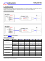
For debugging, the user should connect the target system to a PC via the ICE adapter, as shown below. The ICE
adapter is a bus-powered USB device, and therefore there is no need of a power adapter for it.
Hardware Connection Diagram
Note: Refer to Section 6.5 for more information.
OCD ICE Interface Pin Number
Part No.
MPC82G516
MG82FL(E)532/564
MG84FG516
MG82FG5A32/5A64
MG82FG5Bxx
MG82FG5Cxx
Package
OCD_SCL
OCD_SDA
RST
CLK
40-pin DIP
29
30
N/A
N/A
44-pin PLCC
32
33
N/A
N/A
44-pin QFP
26
27
N/A
N/A
44-pin QFP
26
29
4
5
48-pin LQFP
28
32
5
6
48-pin LQFP
26
27
25
N/A
64-pin LQFP
34
35
33
N/A
48-pin LQFP
26
27
25
N/A
64-pin LQFP
34
35
33
N/A
28-pin SOP
27
28
26
N/A
32-pin LQFP
18
19
17
N/A
48-pin LQFP
26
27
25
N/A
This document information is the intellectual property of Megawin Technology Co., Ltd.
Megawin Technology Co., Ltd. 2014 All right reserved.
4
8051 OCD ICE
MEGAWIN
User Manual, v2.92
MAKE YOU WIN
64-pin LQFP
**N/A : No need to connect
34
This document information is the intellectual property of Megawin Technology Co., Ltd.
Megawin Technology Co., Ltd. 2014 All right reserved.
35
33
N/A
5
MEGAWIN
MAKE YOU WIN
8051 OCD ICE
User Manual, v2.92
3 Software Setup
This section tell the user how to do software setup before using the OCD ICE.
3.1 Install the USB Device Driver for the ICE Adapter
The user just needs to plug the ICE adapter into any USB port in a PC. There is no need to install any device
driver for the ICE adapter.
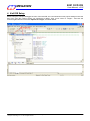
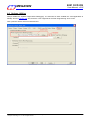
3.2 Install the Megawin 8051 Database in the Keil 8051 IDE Software
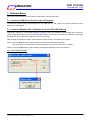
Activate the “Setup.exe” in the folder [Database Installer] to open the Database Installer Application Program to
install the Megawin Database into the Keil 8051 IDE software. Of course, you should have installed the Keil 8051
IDE software, either μVision2 or μVision3, in your PC previously.
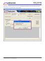
After opening the Database Installer, please follow the steps shown in the following GUI figure.
Step1) Click the Browse button to specify where the Keil software has been installed.
(Normally, when you install the Keil 8051 IDE software, the default install-path is "C:\KEIL".)
Step2) Click the Install button to start installing the Megawin Database into the Keil software.
GUI of the Database Installer
This document information is the intellectual property of Megawin Technology Co., Ltd.
Megawin Technology Co., Ltd. 2014 All right reserved.
6
MEGAWIN
MAKE YOU WIN
8051 OCD ICE
User Manual, v2.92
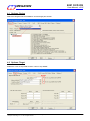
4 Keil IDE Setup
Before using the dScope-Debugger function of the Keil IDE, the user should do some proper settings in the Keil
IDE. First, open the μVision project you would like to debug. Then, move cursor to “Target-..” and click the
mouse‟s right button to invoke the “Options for Target”, as shown below.
This document information is the intellectual property of Megawin Technology Co., Ltd.
Megawin Technology Co., Ltd. 2014 All right reserved.
7
MEGAWIN
MAKE YOU WIN
8051 OCD ICE
User Manual, v2.92
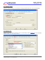
4.1 Options- Device
Select the “Megawin Device Database” and the target part number.
4.2 Options- Target
Enable the “Use on-chip ROM” and the “Use on-chip XRAM”.
This document information is the intellectual property of Megawin Technology Co., Ltd.
Megawin Technology Co., Ltd. 2014 All right reserved.
8
MEGAWIN
MAKE YOU WIN
8051 OCD ICE
User Manual, v2.92
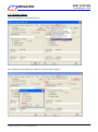
4.3 Options- Output
Enable the “Debug Information”. It is necessary for creating an absolute OMF file for source-level debugging.
4.4 Options- C51
Disable the code optimization by selecting “Level 0: Constant folding”. Refer to Section 6.3 for more information
about this setting. Note: This setting is optional.
This document information is the intellectual property of Megawin Technology Co., Ltd.
Megawin Technology Co., Ltd. 2014 All right reserved.
9
MEGAWIN
MAKE YOU WIN
8051 OCD ICE
User Manual, v2.92
4.5 Options- Debug
Select the “Megawin On-Chip-Debug Driver”.
And, enable the “Load Application at Startup” and all the Cache Options.
This document information is the intellectual property of Megawin Technology Co., Ltd.
Megawin Technology Co., Ltd. 2014 All right reserved.
10
MEGAWIN
MAKE YOU WIN
8051 OCD ICE
User Manual, v2.92
4.6 Options- Utilities
Always disable the “Update Target before Debugging”. It is because we have enabled the “Load Application at
Startup” shown in Section 4.5. And, leave the ”Use Target Driver for Flash Programming” don’t-cared.
Note: μVision2 doesn’t have this selection item.
This document information is the intellectual property of Megawin Technology Co., Ltd.
Megawin Technology Co., Ltd. 2014 All right reserved.
11
MEGAWIN
MAKE YOU WIN
8051 OCD ICE
User Manual, v2.92
5 Start Debugging
After the tasks described in Sections 2, 3 and 4 have been done, you can start debugging your μVision project.
5.1 Activate the dScope-Debugger Function
After building the project (suppose no error), you can enter the Keil IDE‟s debugger mode by clicking the dScope
button, as shown below. Now, the project code will be automatically downloaded into the target‟s Flash. It will
take some time.
This document information is the intellectual property of Megawin Technology Co., Ltd.
Megawin Technology Co., Ltd. 2014 All right reserved.
12
MEGAWIN
MAKE YOU WIN
8051 OCD ICE
User Manual, v2.92
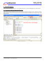
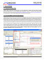
5.2 Introduction to the Debugger Environment
There are four basic windows regarding the debugging operation in the debugger environment. They are Register
Window, Disassembly Window, Watch Window and Memory Window, as described below.
Register Window
This window shows the contents of the current register bank (R0~R7), the system registers (A, B, SP, DTPR and
the Program Counter) and the Program Status Word (PSW). The register with blue background means its content
is just changed due to the instruction just executed.
Disassembly Window
This window is the default window opened just when the debugger mode is entered. It shows the source-level
code followed by its corresponding assembly code.
Watch Window
This window automatically shows the local variables when Locals is clicked. The local variables are the variables
declared within a function including the main() function. To view the global variables, click Watch #1 or Watch #2
and type <F2> key to edit and enter the variable name. The variable with blue background means its content is
just changed due to the instruction just executed.
Memory Window
This window shows the contents of the memory located at the data/idata/xdata/code memory space. The
available commands are: d:0x00~d:0xFF, i:0x00~i:0xFF, x:0x0000~x:0xFFFF and c:0x0000~c:0xFFFF. The user
can view any of the four memory by entering the corresponding command.
This document information is the intellectual property of Megawin Technology Co., Ltd.
Megawin Technology Co., Ltd. 2014 All right reserved.
13
MEGAWIN
MAKE YOU WIN
8051 OCD ICE
User Manual, v2.92
5.2.1 Reset/Run/Halt/Step/Run-to-Cursor
Reset, Run, Halt (Stop), Step and Run-to-Cursor are the basic debug actions. The user can easily invoke any of
these actions by clicking the short-cut buttons in the debugger GUI, as shown below.
5.2.2 Source-Level Debugging
To do the source-level debugging, open the source file by clicking Files to open the Project Workspace and
select the source files you want. Click Regs again to return to Register Window, as shown below.
This document information is the intellectual property of Megawin Technology Co., Ltd.
Megawin Technology Co., Ltd. 2014 All right reserved.
14
MEGAWIN
MAKE YOU WIN
8051 OCD ICE
User Manual, v2.92
5.2.3 Breakpoint Setting
There are total four breakpoints available for debugging. Up to four breakpoints can be inserted simultaneously.
Insert/Remove a Breakpoint
Move the cursor to the front of the line and click the right key, then click “Insert/Remove Breakpoint” for toggling
between Insert and Remove, as shown below.
Enable/Disable a Breakpoint
Move the cursor to the front of the line and click the right key, then click “Enable/Disable Breakpoint” for
toggling between Enable and Disable. Of course, this line should have been inserted a breakpoint previously.
This document information is the intellectual property of Megawin Technology Co., Ltd.
Megawin Technology Co., Ltd. 2014 All right reserved.
15
MEGAWIN
MAKE YOU WIN
8051 OCD ICE
User Manual, v2.92
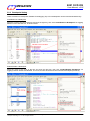
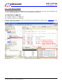
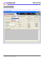
5.2.4 View/Edit the Contents of Peripherals’ SFRs
There are many peripheral SFRs that don‟t belong to the registers shown in the Register Window. To view or edit
these registers, select the Peripherals item on the main menu. A pulled-down sub-menu will be displayed, and
the user can select a peripheral to view or edit its corresponding SFRs, as shown below.
This document information is the intellectual property of Megawin Technology Co., Ltd.
Megawin Technology Co., Ltd. 2014 All right reserved.
16
MEGAWIN
MAKE YOU WIN
8051 OCD ICE
User Manual, v2.92
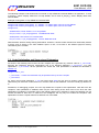
5.2.5 View- Disassembly Window
Disassembly Window displays source-level code followed by its corresponding assembly. To open this window,
select the View item on the main menu. A pulled-down sub-menu will be displayed, and then select
Disassembly Window, as shown below.
Maximize the Disassembly Window for detailed description:
This document information is the intellectual property of Megawin Technology Co., Ltd.
Megawin Technology Co., Ltd. 2014 All right reserved.
17
MEGAWIN
MAKE YOU WIN
8051 OCD ICE
User Manual, v2.92
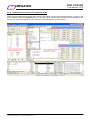
5.2.6 View- Watch Window
The Watch Window helps the user to check either local variables or global variables, as shown below.
To check the global variables, click Watch #1 or #2, then type <F2> key to enter the variable name.
This document information is the intellectual property of Megawin Technology Co., Ltd.
Megawin Technology Co., Ltd. 2014 All right reserved.
18
MEGAWIN
MAKE YOU WIN
8051 OCD ICE
User Manual, v2.92
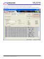
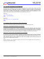
5.2.7 View- Memory Window
To open this window, select the View item on the main menu. A pulled-down sub-menu will be displayed, and
then select Memory Window, as shown below. The available commands are:
(1)
(2)
(3)
(4)
d:0x00~d:0xFF, for „data‟ type
i:0x00~i:0xFF, for „idata‟ type
x:0x0000~x:0xFFFF, for „xdata‟ type
c:0x0000~c:0xFFFF., for „code‟ type
The user can view any of the four memory by entering the corresponding command. Refer to Section 6.2 for how
to display „xdata‟ type variables.
This document information is the intellectual property of Megawin Technology Co., Ltd.
Megawin Technology Co., Ltd. 2014 All right reserved.
19
MEGAWIN
MAKE YOU WIN
8051 OCD ICE
User Manual, v2.92
6 Tools, Megawin ICP
6.1 About ICP
ICP is the acronym of In-Circuit Programming. Users can update the application code under the software control
without removing the mounted MCU chip from the actual end product. In addition, because the programming data
to be programmed to the target can be saved in the ICE adapter‟s non-volatile storage, this stand-alone
programmer is able to work without host(PC) intervention. This feature is especially useful in the field without a
PC.
6.2 Use ICP
Here are the two ways of opening ICP application:
1. Execute “ICPProgrammer.exe” under “\C51\INC\Megawin\” of Keil‟s Install folder.
2. Click “Tools\Megawin ICP” from Keil‟s Menu bar.
Attention: To program ICP application correctly by means 2, users have to open Project and Build first.
This document information is the intellectual property of Megawin Technology Co., Ltd.
Megawin Technology Co., Ltd. 2014 All right reserved.
20
MEGAWIN
MAKE YOU WIN
8051 OCD ICE
User Manual, v2.92
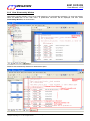
6.2.1 Update Programmer
Step 1: Choose a “MCU Part No.”
If users open ICP application by clicking Menu, Step 1 can be omitted. ICP application will choose MCU Part No.
by Project automatically.
This document information is the intellectual property of Megawin Technology Co., Ltd.
Megawin Technology Co., Ltd. 2014 All right reserved.
21
MEGAWIN
MAKE YOU WIN
8051 OCD ICE
User Manual, v2.92
Step 2: Click “Load File” and choose loading AP(Code) or IAP(Data). “Load File” can be clicked repeatedly to
load different files. While loading IAP(Data), users have to key in Address. HEX and BIN data formats are
supported for file loading.
If users open ICP application by clicking Menu, Step 2 can be omitted. ICP application will load Target file
automatically.
This document information is the intellectual property of Megawin Technology Co., Ltd.
Megawin Technology Co., Ltd. 2014 All right reserved.
22
MEGAWIN
MAKE YOU WIN
8051 OCD ICE
User Manual, v2.92
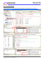
Step 3: Click “Insert ISP-Code” may choose to insert Megawin-provided ISP code or User-defined ISP code.
If ISP function is not needed, Step 3 can be omitted.
This document information is the intellectual property of Megawin Technology Co., Ltd.
Megawin Technology Co., Ltd. 2014 All right reserved.
23
MEGAWIN
MAKE YOU WIN
8051 OCD ICE
User Manual, v2.92
Step 4:H/W Option Setting
This document information is the intellectual property of Megawin Technology Co., Ltd.
Megawin Technology Co., Ltd. 2014 All right reserved.
24
MEGAWIN
MAKE YOU WIN
8051 OCD ICE
User Manual, v2.92
Step 5: Click “Update Programmer” to download programming data to the ICE adapter.
“Update Programmer” function can be chosen only when connecting an ICE adapter (Only support TH065C or
later versions).
This document information is the intellectual property of Megawin Technology Co., Ltd.
Megawin Technology Co., Ltd. 2014 All right reserved.
25
MEGAWIN
MAKE YOU WIN
8051 OCD ICE
User Manual, v2.92
6.2.2 Update Target
How to update the target? Users may
1. click “Update Target” to program on-line update, referring to steps 1 through 4 of 6.2.1 Update Programmer, or
2. click “Downloading” of ICE adapter to program off-line update, referring to 6.2.1 Update Programmer.
This document information is the intellectual property of Megawin Technology Co., Ltd.
Megawin Technology Co., Ltd. 2014 All right reserved.
26
MEGAWIN
MAKE YOU WIN
8051 OCD ICE
User Manual, v2.92
7 Special Notes
7.1 Register Definition Files
Register definition files REG_MPC82G516.INC and REG_MPC82G516.H define all Special Function Registers
(SFRs) and bit-addressable control/status bits. They are installed into the default search path used by the Keil
8051 IDE software when you do the Software Setup (described in Section 2). Therefore, when using the Keil
8051 tools, you can include them by $INCLUDE (REG_MPC82G516.INC) and #include <REG_MPC82G516.H>.
It is not necessary to copy a register definition file to each project‟s file directory.
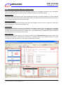
7.2 On-chip XRAM and External Data Memory
Megawin 8051 devices provide on-chip XRAM (eXpanded RAM), which is accessed with the same instructions
as the traditional external data memory. The size of on-chip XRAM in MPC82G516 is 1024 bytes with addresses
0x0000 to 0x03FF. That is, the address space of on-chip XRAM overlaps that of the external data memory. So,
there must be a control bit used to distinguish these two physical memories during access. The ERAM bit (bit-1 in
register AUXR) plays this role. Because the C51 Compiler won’t take care which physical memory the user wants
to access, the user must manually clear this bit before accessing on-chip XRAM and set this bit before accessing
external data memory. By default, this control bit is „0‟ after powered on or chip reset for on-chip XRAM accessing.
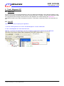
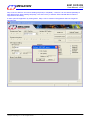
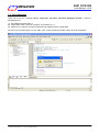
The C51 Compiler offers two different memory types that access external data: xdata and pdata. (The xdata
memory specifier refers to any location in the 64K-byte address space of external data memory. The pdata
memory type specifier refers to only one page or 256 bytes of external data memory.) When the user want to
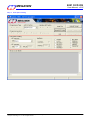
view the variables declared by xdata or pdata directly in the Memory Window rather than in the Watch Window,
he should select “Display xdata from on-chip XRAM” or “Display xdata from external RAM” under menu
Peripherals- XRAM, as shown in the following figure.
This document information is the intellectual property of Megawin Technology Co., Ltd.
Megawin Technology Co., Ltd. 2014 All right reserved.
27
MEGAWIN
MAKE YOU WIN
8051 OCD ICE
User Manual, v2.92
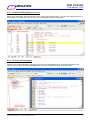
The following example code shows how to use both on-chip XRAM and external RAM in an application. To view
G_array1[ ], select “Display xdata from on-chip XRAM”; and to view G_array2[ ], select “Display xdata from
external RAM”.
Example of using both on-chip XRAM and external RAM
unsigned char xdata G_array1[512] _at_ 0x0000; // in 'xdata' space, will use on-chip XRAM
unsigned char xdata G_array2[512] _at_ 0x0000; // in 'xdata' space, will use ext. RAM
unsigned int i;
AUXR&=0xFD; //clear AUXR.1 for on-chip XRAM
for (i=0; i<512; i++) G_array1[i]=0x5A; // fill XRAM with 0x5A
AUXR|=0x02; //set AUXR.1 for external RAM
for (i=0; i<512; i++) G_array2[i]=0xA5; // fill ext. RAM with 0xA5
Note that there will be a linking warning listed below. However, it doesn‟t matter because we intentionally declare
G_array1 and G_array2 in the same address space. In fact, we access to the different physical memory
controlled by bit-1 of AUXR.
7.3 Code Optimization and Source-Level Debugging
As shown in the following source code, the C51 compiler won‟t generate any machine code for “L_var1=0x38;”
because this statement becomes meaningless due to its following statement “L_var1=0xC7;”. For code
optimization, “L_var1=0x38;” will be optimized out unless the code optimization is disabled as described in
Section 4.4.
unsigned char L_var1;
L_var1=0x38; // ! Note: this statement may be optimized out by the C51 compiler
L_var1=0xC7;
So, during source-level debugging, L_var1 will never show 0x38 but may show a random number when this
statement is just executed. In fact, there in no machine code for this statement. The user should pay attention to
it!
Sometimes, for debugging purpose, the user may disable the compiler‟s code optimization. Note that once the
compiler‟s code optimization is disabled, there may be some linking errors which won‟t occur when the code
optimization is enabled. For example, refer to the following linking error message, it means the variables you use
exceed the RAM an MCU has. To make this error disappear, the only way is to enable the compiler‟s code
optimization to let the compiler make more efficient use of the RAM.
This document information is the intellectual property of Megawin Technology Co., Ltd.
Megawin Technology Co., Ltd. 2014 All right reserved.
28
MEGAWIN
MAKE YOU WIN
8051 OCD ICE
User Manual, v2.92
7.4 “for-Loop” and Source-Level Debugging
The following two statements are fully the same for the 8051 CPU to execute them. During source-level
debugging, there is no problem to apply Step action on Statement 1. However, it will take so much time if the
user apply Step action on Statement 2. We think it is caused by unknown processing in the Keil debugger
function. Before we getting the reply from Keil, we suggest using Statement 1 instead of Statement 2 in the
source code if you want to do step-debugging in such statement. Another solution for Statement 2 is: move
cursor to Line2 and click left key, then click Run-to-Cursor button to fly over Line 1.
Statement 1:
Line1: for (i=0; i<16; i++) {
Line2:
G_array1[i]=i+0x60;
Line3:
}
Statement 2:
Line1: for (i=0; i<16; i++) G_array1[i]=i+0x60;
Line2: …
Line3: …
7.5 Hardware Option Requirements During Debugging
There are two requirements regarding the hardware option in the dScope-Debugger mode:
Requirement 1: The debugged chip must be in un-locked state
It is because if the debugged chip is locked, the downloading of the user‟s application code in the dScopeDebugger mode will cause the chip to be whole-chip erased, and therefore all the chip‟s hardware options will be
disabled. Thus the debugged chip may not work well owing to losing its original hardware options. For example,
for a locked chip with IAP-memory configured, after downloading the user‟s application code when entering the
dScope-Debugger mode, its IAP-memory will disappear (i.e., disabled). So, the chip cannot work well.
Requirement 2: The ISP function of the debugged chip must be disabled
It is because if the ISP function is enabled, the debugged chip will always boot from the ISP-memory and run the
ISP-code when the chip receives the Reset command in the dScope-Debugger mode. It will cause a problem.
That is, the code the MCU runs (i.e., the ISP-code) is different from the code of the opened Keil project (i.e., the
user‟s application code). So, during debugging, the user needs to disable the ISP function by having the
hardware option HWBS disabled temporarily.
Note:
After the application code is debugged completely, the user may use the “Megawin 8051 ICP Programmer” to
restore the original hardware option.
This document information is the intellectual property of Megawin Technology Co., Ltd.
Megawin Technology Co., Ltd. 2014 All right reserved.
29
MEGAWIN
MAKE YOU WIN
8051 OCD ICE
User Manual, v2.92
7.6 Error Message
There will be an error message “Error: Target DLL has been cancelled. Debugger aborted !” shown in
following figure if:
(1) ICE adapter hardware fails, or
(2) Target MCU doesn‟t work (for example, not powered on), or
(3) Cable error or improper connection between ICE adapter and the Target MCU.
Once the error message pops out, click “OK”. Then, check the above possible causes to solve the problem.
This document information is the intellectual property of Megawin Technology Co., Ltd.
Megawin Technology Co., Ltd. 2014 All right reserved.
30
MEGAWIN
MAKE YOU WIN
8051 OCD ICE
User Manual, v2.92
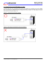
7.7 Properly Connect the ICE Adapter to a Host
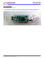
The data transfer rate of the ICE adapter will be slowed down severely if it is connected to a host via a USB2.0
hub. So, to speed up the downloading when clicking dScope button to enter the debugger mode, the user had
better directly plug the ICE adapter into the host‟s USB port, as shown in Figure 6.7.1. Don‟t plug into a hub and
then to the host, as shown in Figure 6.7.2.
Figure 6.7.1 Directly plug into the host‟s USB port
Figure 6.7.2 Don‟t plug into a hub and then to the host‟s USB port
This document information is the intellectual property of Megawin Technology Co., Ltd.
Megawin Technology Co., Ltd. 2014 All right reserved.
31
8051 OCD ICE
MEGAWIN
User Manual, v2.92
MAKE YOU WIN
Revision History
Revision
Description
Date
v1.00
The first release for beta-site test.
2007/08/15
v1.01
Add notes when installation fails. (Section 3.2)
2007/08/24
v1.02
Change to manually specify the installation path of the Keil software. (Section 3.2)
2007/08/27
Add the notification of default installation path of Keil 8051 IDE software. (Section 3.2) 2007/08/29
v2.00
Update the Keil IDE Setup. (Section 4.4)
2007/10/08
Update the Special Notes. (Section 6)
2007/10/08
The formal released version.
2007/10/08
V2.31
(1) Improve the defect of breakpoint setting.
(2) Fix the bug of wrong erasing range when downloading the application code.
(1) Update the data base for all series of MCU in Driver Installer.
(2) Removed the function of detecting the ICE adapter when install Driver.
Change the folder name of Driver Install to Database install
(1) Supported MG82FL(E)532 and MG82FL(E)564
(2) Supported ICP function
Update “Database Installer “
V2.32
Support uVision4
2010/06/02
V2.33
Update “IcpProgrammer.exe” in Database Installer
2010/08/25
V2.40
Supported MG84FG516
2011/05/02
V2.41
Update “IcpProgrammer.exe” in Database Installer
2011/06/01
V2.50
Support Off-Line Mode programming
2011/10/20
V2.51
Support H/W ver.TH065E to prevent to damage the MG84FG516
2012/04/01
V2.52
Fix the bug on ICP function for MG84FG516
2012/05/01
V2.53
Update “IcpProgrammer.exe” in Database Installer
(1) Supported “Maximum Counter” in Off-Line Mode programming
(2) Supported “ Serial Number “ in Off-Line Mode programming
(3) Improve the performance on Off-Line Mode programming.
Fix the bug on ICP function
2012/05/15
2012/10/08
V2.62
Fix the bug on ICE function
(1) Supported “MPJ” file
(2) Database support MG86FL(E)104 and MG86FL(E)508
(3) Supported MG82FG5A64
(4) Update “ warning message “ when OCD ICE in update processing
(1) Fix a bug for MG84FG516 at access P6M0 in debug mode
(2) Update “ Megawin.dat “
Update “IcpProgrammer.exe” in Database Installer
V2.63
Supported MG82FG5A32
2013/06/27
V2.64
2013/09/27
V2.71
Update the Hardware Setup. (Section 2)
(1) Supported MG82FG5B(32/16)
(2) Supported MG20FL(E)809
Supported MG82FG5B(24/08)
V2.72
Update H and INC files in H and INC folder
2014/05/15
V2.90
Supported MG82FG5C(64/32)
2105/04/15
v2.10
V2.20
V2.21
V2.30
V2.54
V2.55
V2.56
V2.60
V2.61
V2.70
This document information is the intellectual property of Megawin Technology Co., Ltd.
Megawin Technology Co., Ltd. 2014 All right reserved.
2007/12/26
2009/02/27
2009/04/01
2010/05/10
2010/05/21
2012/07/12
2012/09/28
2012/12/10
2013/01/10
2013/01/14
2103/11/15
2104/04/09
32
MEGAWIN
MAKE YOU WIN
8051 OCD ICE
User Manual, v2.92
V2.91
Update “IcpProgrammer.exe” in Database Installer
2015/05/21
V2.92
Update “IcpProgrammer.exe” in Database Installer
2015/05/22
This document information is the intellectual property of Megawin Technology Co., Ltd.
Megawin Technology Co., Ltd. 2014 All right reserved.
33