1
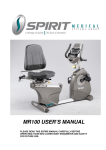
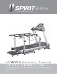
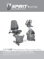
MR100 Rehabilitation Recumbent Bike USER’S MANUAL PLEASE READ THIS ENTIRE MANUAL CAREFULLY BEFORE OPERATING YOUR NEW LOWER BODY ERGOMETER AND SAVE IT FOR FUTURE USE. Table of Contents Product Registration…………………………………………………………………………. 2 Important Safety Instructions………………………………………………………………… 3 Important Electrical Information……………………………………………………………… 4 Important Operation Instructions…………………………………………………………….. 4 Features……………………………………………………………………………………….. 5 Operation of Your New Bike…………………………………………………………….…… 7 MR100 Assembly Instructions………………………………………………………………. 20 MR100 Drawing & Parts List………………………………………………………………… 30 Maintenance…………………………………………………………………………………… 36 Specifications………………………………………………………………………………….. 37 Manufacturer’s Limited Warranty…………………………………………………………….. 38 1 MR100 Thank you for your recent purchase of this high quality lower body ergometer, the MR100, from Spirit Medical Systems Group. Your new product was manufactured by one of the leading fitness and medical products manufacturers in the world. Further, it is backed by one of the most comprehensive warranties in the industry. Through our dealers, distributors and manufacturer’s representatives, we will do all we can to provide many years of successful and prosperous ownership. Your warranty and service needs will be addressed collaboratively through your regional sales representative and our highly trained service technicians. The responsibility of that collaborative team is to provide you with both the technical knowledge and access to service personnel to make your ownership experience more informed, and resolution of any difficulties easier to remedy. Two components of the Spirit Medical Systems Group’s mission statement are “enhancing patient outcomes and improving effectiveness in the delivery of services”. This is just one of the many products that will assist you in providing that care to your patients and/or clients. Please take a moment at this time to record the name of the dealer, distributor, or manufacturer’s representative, their telephone number, and the date of purchase below to make any future, needed contact easy. We appreciate your support and we will always remember that you are the reason that we are in business. Please complete and mail your registration card today and enjoy your new MR100 ergometer. Yours in Health and Wellness, Spirit Medical Systems Group Product Registration RECORD YOUR SERIAL NUMBER Please record the Serial Number of this product in the space provided below. You can find the serial number on a sticker that is located on the front of the bike. Serial Number_______________________________________ REGISTER YOUR PURCHASE The self-addressed product registration card must be completed in full and returned to Spirit or visit: www.spiritmedicalsystems.com to register online. 2 MR100 Important Safety Instructions ATTENTION - Read all instructions in this manual before using this device. DANGER - To reduce the risk of electric shock disconnect your ergometer from the electrical outlet prior to cleaning and/or service work. WARNING - To reduce the risk of burns, fire, electric shock, or injury to persons, install the bike on a flat level surface with access to a 110 to 230-volt AC, 50/60 Hz, 15-amp grounded outlet. Do not use an extension cord unless it is 16awg or larger, with only one outlet on the end. The bike should be the only appliance in the electrical circuit. Do not attempt to disable the grounded plug by using improper adapters, or in any way modify the cord set; a serious shock or fire hazard may result along with computer malfunctions. Use this device only for it’s intended use as described in this manual. Keep children away from the bike. There are moving parts, obvious pinch points and other caution areas that can cause harm. Except as instructed for use of the device, keep hands away from all moving parts. Keep the electrical cord away from heated surfaces and out of all travel lanes and do not operate the bike if the cord or plug is damaged. Never drop or insert any object into any openings. Do not use outdoors. To disconnect, turn all controls to the off position then remove the plug from the outlet. This device is designed for commercial use and will meet the demands of orthopedic, sports wellness and general conditioning programs. Do not attempt to use your bike for any purpose other than for the purpose it is intended. The pulse sensors are not medical devices. Various factors, including the user’s movement, may affect the accuracy of heart rate readings. The pulse sensors are intended only as exercise aids in determining heart rate trends in general. WARNING: Heart rate monitoring system may be inaccurate. Over exercise may result in injury or death. If you feel faint stop exercising immediately. Ensure there is a minimum space on the sides of the bike of two feet for proper operation, easy access and to prevent possible injuries to others standing or walking nearby. There should be a minimum of at least one foot of free space at the front and rear of the unit. Do not use any after market parts on this device, other than those recommended by Spirit. Do not attempt any servicing or adjustments other than those described in this manual. All else must be left to trained service personnel familiar with electro-mechanical equipment and authorized under the laws of the country in question to carry out maintenance and repair work. Hold the handlebar for support when getting on or off the bike. To avoid injury please observe all minimum and maximum seat adjustment settings. Warning: The adjustable crank arms may become entangled in pant legs if the pant legs are loose fitting. To avoid injury roll up the pant legs or secure the pant legs in some other fashion. The flywheel in the bike does not have a freewheel, but is directly connected to the pedals. The bike is equipped with auto-braking software that will stop the flywheel when it detects the user is trying to stop pedaling. In the unlikely event that the electronics fails, or the Auto-brake function is disabled in the software, a spinning flywheel can make the bike difficult to stop when pedaling at higher RPM. There is an emergency brake lever provided that will stop the flywheel when pressed. 3 MR100 Important Electrical Information WARNING! NEVER remove any cover without first disconnecting AC power. If voltage varies by ten percent (10%) or more, the performance of your bike may be affected. Such conditions are not covered under your warranty. If you suspect the voltage is low, contact your local power company or a licensed electrician for proper testing. NEVER expose this bike to rain or moisture. This product is NOT designed for use outdoors, near a pool or spa, or in any other high humidity environment. The temperature specification is 40 degrees c (104 deg f), and humidity is 95%, non-condensing (no water drops forming on surfaces). Grounding Instructions This product must be grounded. In the unlikely event that the bike’s electrical system should malfunction or breakdown grounding provides a path of least resistance for electric current, reducing the risk of electric shock. This product is equipped with a cord having an equipment-grounding plug. The plug must be plugged into an appropriate outlet that is properly installed and grounded in accordance with all local codes and ordinances. DANGER - Improper connection of the equipment-grounding conductor can result in a risk of electric shock. Check with a qualified electrician or serviceman if you are in doubt as to whether the product is properly grounded. Do not modify the plug provided with the product if it will not fit the outlet; have a proper outlet installed by a qualified electrician. Important Operation Instructions ● ● ● ● NEVER use your bike during an electrical storm. Surges may occur in your facility power supply that could damage the bike’s components. All users should have medical clearance before starting any rigorous exercise program. Start the user at a safe exercise level. Do not allow the user to be over exerted. Symptoms to watch for, but not limited to, are: Shortness of breath or difficulty in breathing, pain or discomfort, feeling faint. Make sure the user warms up and cools down properly to avoid over taxing the cardio vascular system. Allow three to five minutes of warm up and cool down during each exercise session. 4 MR100 Features 1 2 5 6 8 3 7 4 9 MR100 – Rehabilitation Ergometer Parts and Adjustments: 1. 2. 3. 4. 5. 6. 7. 8. 9. MA901 Neurological Pedals Optional Parts: Electronic Console Mechanical Brake Pedal Adjustment A.C. Power Input Swivel Seat Release Bar Hand Pulse Sensors Seat Back Angle Adjustment Seat Fore/Aft Adjustment Leveling Glide 1. Neurological Pedal Set The Spirit MR100 is an easy product to set up and use, from the adjustments to the intuitive interface. This section explains how to set up, adjust and operate your MR100 from Spirit Medical Systems Group. Leveling the MR100: Once the MR100 is assembled, and placed on a flat level floor, it may be necessary to adjust the leveling glides on the bottom of the unit to ensure proper stability of the MR100. Use a 1/2” wrench to loosen the top nut of the leveler. Adjust the levelers by hand as necessary to remove any wobble in the unit. Then tighten the top nut against the bottom of the stabilizer tube. Make sure the bottom nut remains cinched against the leveling foot. 5 MR100 Connecting to A.C. Power: The MR100 has a built-in universal power supply. You can plug the MR100 into any A.C. power source from 90 to 260 volts, 47 to 63 Hz. The A.C. input is located in the front of the unit. The input module has an input connector for the line cord, a power switch and a 5 amp fuse. Turn the power switch to off when the MR100 is not in use. Seat Adjustments Lift handle to rotate seat. Lower handle to activate latch Seat position number lines up with front edge of seat carriage Seat back angle indicator Adjusting the seat fore/aft position: Lift the yellow handle below the front of the seat. Move the seat to the desired position and lower the handle. Move the seat slightly until the seat lock clicks in place. There is a numbered scale located on the aluminum seat slide tube for repeatable settings. Seat position is indicated by the front of the seat carriage lining up with the number on the scale. Adjusting the seat back angle: The seat back angle can be adjusted for comfort, but also may be adjusted to change the hip angle for patients. To adjust the seat back angle, squeeze the brake handle located on the right side handle bar and move the seat back to the desired position. There is a numbered scale located just below the seat back cushion for repeatable settings. Rotating the swivel seat: Lift the handle behind the seat to disengage the latch. Rotate the seat to the desired position; lower the handle when approaching position to activate latch. The seat will latch into place every 45 degrees Pedal adjustment: Loosen the knob on the adjustable crank and pull up to disengage the pin. Slide the pedal up or down the crank arm to the desired setting then tighten the knob. There is a numbered scale for repeatability and a program in the Set Up function of the console that can assist in setting up the pedal position to accommodate various patient knee angles. Warning: Avoid wearing pants with loose fitting legs as they may get caught on the crank arm while pedaling. Auto-Braking Feature: The MR100 has built-in sensing technology and software that will automatically stop the flywheel when it senses the user is attempting to stop pedaling. This Auto-braking software can be disabled during program set up before beginning a session. The Auto-Brake is set to off for the Symmetry and VO2 programs and can be turned on during program set up. Mechanical Brake Lever Function: The brake’s flywheel is also equipped with a mechanical brake that can be activated to stop the flywheel by pressing down on the lever. 6 MR100 MR100 Electronic Console: DOT MATRIX DISPLAY RPM SCALE FOR ISOKINETICS ONLY CHANGE GRAPHIC DISPLAY PROGRAM KEYS PROGRAM KEYS SET UP KEY MESSAGE WINDOW CHANGE DATA DISPLAYED FUNCTION KEYS Power on When initially powered on the console will perform an internal self-test. During this time all the lights will turn on for a short time. The dot matrix display will then show a software version (i.e. VER 1.0) and the message window will display an odometer reading. The odometer reading displays how many hours the bike has been used and how many virtual miles the bike has been ridden. The display will look like this: ODO 123 MI 123 HRS. The odometer will remain displayed for only a few seconds then the console will go to the start up display, also known as Idle Mode. The dot matrix display will be scrolling through the different program profiles and the message window will be scrolling the start up message. You may now begin to use the MR100. The console will automatically power down after 20 minutes of inactivity. Press any key to wake the console up again. Always turn off the main power switch when the MR100 is not in use. 7 MR100 Console Operation: 1. Set Up The Set Up key function will allow you to enter patient data, set seat and pedal adjustments for various knee ranges of motion and customize the settings of the MR100. When the Set Up key is pressed the first option in the menu appears. Use the up/down arrows to scroll through the menu and press the enter key to select an option. Set Up menu: 1. Patient Data: Age: used in Vo2 and heart rate programs. Gender: used in Vo2 program. Weight: used in METs and Calorie calculations and Vo2 program. Height: used in the seat position and pedal crank set up program. 2. Seat Position: User may input desired knee flexion angles (6 options) and the software will calculate the seat’s fore/aft position and pedal position settings. This feature is intended to aid in patient set up but may not be the final settings as patient’s body symmetry may vary slightly. This program uses the height from the Patient Data settings for limb length. The seat back angle position is assumed to be in the center of the adjustment range. The six knee angle options are: 1. 2. 3. 4. 5. 6. R Min (Right leg minimum flexion) R Max (Right leg maximum flexion) R Max (Right leg maximum flexion) R Min (Right leg minimum flexion) R Max (Right leg maximum flexion) L Max (Left leg maximum flexion) L Min (Left leg minimum flexion) L Max (Left leg maximum flexion) L Min (Left leg minimum flexion) L Max (Left leg maximum flexion) R Min (Right leg minimum flexion) L Min (Left leg minimum flexion) 3. Watts Per Row: Adjusts the scale of the dot matrix when power (watts) is displayed. The default setting is 10 watts per row. The default of 10 watts per row means the full display (all 10 rows lit) equal 100 watts. The setting can be adjusted from 10 to 100 watts per row of lights on the graph. 4. Level Scale: Set the amount of change in the level adjustment of workload (resistance at the pedals) each time the arrow keys are pressed. This feature allows you to have very fine increments of resistance for physically challenged patients or set very high resistance levels for sports training. The default setting is; Fine, 5 watts per level. The three options are: 1. Fine – 5 watts per level (at 60 rpm) 2. Medium – 10 watts per level (at 60 rpm) 3. Coarse – 15 watts per level (at 60 rpm) 8 MR100 2. Quick Start This is the quickest way to start an exercise session. After the console powers up you just press the Start key to begin; this will initiate the Quick Start mode. In Quick Start, the Time will count up from zero, all workout data will start to accrue and the workload may be adjusted manually by pressing the Up or Down key. The dot matrix will display a workload level at the lowest resistance. As you increase the workload more rows will light indicating a harder workout. The bike will get harder to pedal as the rows increase. The dot matrix has 24 columns of lights and each column represents 1 minute in the Quick Start program (time per column can be modified in other programs). At the end of the 24th column (or 24 minutes of work) the display will wrap around and restart at the first column again. There are 50 levels of resistance displayed in 10 rows of LED lights. The amount of workload for each level can be modified in the Set Up menu. 3. Basic information The Dot Matrix Display is used for displaying graphic feedback and has three basic displays for most programs, except for Isokinetic and Symmetry programs which are described later. When you begin a program the dot matrix will display a workload profile (constant resistance). To the left of the dot matrix there is a key labeled Display. Pressing this key will switch the display to show a Power graph (watt profile) and then a track. When both LEDs under the key are blinking the graph will scan through the three displays. The Message Window is the main display for programming instructions and relevant measurements during a program. The measurement data shown varies depending on the program. Measurements include: Time and Segment Time, RPM, Pulse, Work level, Watts and Average Watts (Left and Right leg), METs, Calories and Symmetry. Below the Dot matrix display is a Heart Icon and a Bar Graph. Simply grasping the hand pulse sensors, or wearing a heart rate chest belt transmitter, will start the Heart Icon blinking (this may take a few seconds). The Message Window will display your heart rate in beats per minute. The Bar Graph represents the percentage of maximum heart rate. NOTE: Enter the correct age in Set Up for the Bar Graph to be accurate. Refer to Heart Rate section for details about these features. The Stop/Reset key provides several functions. Pressing the Stop/Reset key once during a program will Pause the program. To resume the exercise session just press the Start key or start pedaling. If the Stop/Reset button is pressed twice during a workout the program will end and a summary of information of the exercise session will be displayed. If the Stop/Reset key is held down for 3 seconds the console will perform a complete Reset. During data entry for a program the Stop/Reset key performs a Previous Screen function. This allows you to go back one step in the programming each time you press the Stop/Reset key. The Program Keys may be used to preview each program when in the idle mode. Press each program key to preview what the program profile looks like. To begin a program press the corresponding program key and then press the Enter key to select the program. The program keys also function as a Number Key Pad when you are in the data-setup mode. The number for each key is shown above the program name. If you are entering new data such as Time, Age, weight etc., you can use these keys to enter the numbers quickly. 9 MR100 4. Selecting and customizing programs When you enter a program you have the option of modifying the settings. If you want to begin without entering new settings just press the Start key. This will bypass the programming of data and take you directly to the start of the program. If you want to change the settings just follow the instructions in the message window. If you start a program without changing the settings the data from the Set Up menu will be used. Manual The Manual program works as the name implies, manually. This means that you control the workload yourself, not the computer. To start the Manual program follow the instructions below or just press the Manual button then the Enter button and follow the directions in the message window. 1. Press the Manual key then press the Enter key. 2. The message window will prompt you to enter the time for the program. You may enter the time using the Up and Down keys or the numeric key pad then press the Enter key to accept and proceed to the next screen. 3. The next setting is for the Auto-braking feature. You may turn the auto-brake on or off then press enter to continue. 4. Now you are finished editing the settings and can begin the program by pressing the Start key. You can also go back and modify your settings by pressing the Enter key. NOTE: At any time during the editing of Data you can press the Stop key to go back one level, or screen. 5. During the Manual program you will be able to scroll through the data in the message window by pressing the Display key. You may also switch between the profile or power displays and a quarter mile track by pressing the Display key adjacent to the dot matrix display. 6. When the program ends you may press Start to begin the same program again or Stop to exit the program, or you can save the program you just completed as the Facility program by pressing the Facility key and following the instructions in the message window. Preset Programs The bike has three preset exercise programs that have been designed for a variety of workout goals. The initial built-in level of difficulty for each program is set to a relatively easy level. You may adjust the level of difficulty (Max level) for each program before beginning. The profiles shown in the dot matrix are merely pictures of the whole profile and will not change in size when the work level keys are pressed. When setting up a program you will enter the maximum resistance setting for the peak of the profile. During the program the resistance levels will change as the profile progresses. When the up key is pressed to request more resistance the profile picture will not change, but the workload will increase. The message window will display the level setting for the current segment and also the maximum level for the peak of the profile. Pressing the work keys actually change the peak level of the program not the current segment level. You may need to change the peak setting several times before the current segment increases. 10 MR100 HILL The Hill program simulates going up and down a hill. The resistance in the pedals will steadily increase and then decrease during the program. PLATEAU The Plateau program provides a steady state exercise with warm up and cool down periods. Interval The Interval program takes you through high levels of intensity followed by periods of low intensity. This program increases your endurance by depleting your oxygen level followed by periods of recovery to replenish oxygen. Your cardio vascular system gets programmed to use oxygen more efficiently this way. Programming Preset Programs: 1. Select the desired program button then press the Enter key. 2. The message window will prompt you to enter the time for the program. You may enter the time using the Up and Down keys or the numeric key pad then press the Enter key to accept and proceed to the next screen. 3. The next setting is for the Auto-braking feature. You may turn the auto-brake on or off then press enter to continue. 4. Now you are finished editing the settings and can begin the program by pressing the Start key. You can also go back and modify your settings by pressing the Enter key. NOTE: At any 11 MR100 time during the editing of Data you can press the Stop key to go back one level, or screen. 5. During the Manual program you will be able to scroll through the data in the message window by pressing the Display key. You may also switch between the profile or power displays and a quarter mile track by pressing the Display key adjacent to the dot matrix display. 6. When the program ends you may press Start to begin the same program again or Stop to exit the program, or you can save the program you just completed as the Facility program by pressing the Facility key and following the instructions in the message window. Facility Program The Facility program allows you to build and save a custom program. You can build your own custom program by following the instructions below or you can save any other preset program you complete as a custom program. The Facility program allows you to further personalize it by adding your facility name. Designing and saving a new program: 1. Press the Facility key. The message window will show a welcome message; if you had previously saved a program the message will contain the name you gave it. Then press the Enter key to begin programming. 2. When you press enter, the message window will show “Name – A”, if there is no name saved. If the name “Custom Workout” had been previously saved the message window will show “Name – Custom Workout” and the C in Custom will be blinking. If there is a name saved you can change it or you may press the Stop key to keep the name and continue to the next step. If you want to enter a name use the Up and/or the Down key to change the first letter then press Enter to save the first letter and continue to the next letter. When you have finished entering the name press the Stop key to save the name and continue to the next step. 3. The message window will ask you to enter an Age. You may enter an Age, using the Up and Down keys or the numeric key pad, then press the Enter key to accept the new number and proceed on to the next screen. 4. You are now asked to enter a Weight. You may adjust the Weight number using the Up and Down keys or the numeric key pad then press enter to continue. 5. Next is Time. You may adjust the Time and press enter to continue. 6. Now you are asked to adjust the Max Level. This is the peak exertion level you will experience during the program. Adjust the level and then press enter. 7. Now the first column will be blinking and you are asked to adjust the level for the first segment of the workout. When you finish adjusting the first segment, or if you don’t want to change, then press enter to continue to the next segment. 8. The next segment will show the same level as the previously adjusted segment. Repeat the same process as the last segment then press enter. Continue this process until all twenty four segments have been set. 9. The message window will then tell you to press enter to save the program. After saving the program the message window says “New program saved” then will give you the option to Start or modify the program. Pressing Stop will exit to the start up screen. 10. During the Facility program you will be able to scroll through the data in the message window by pressing the adjacent Display key. Running a saved program: 1. Press Facility key then Enter 2. Enter Time then set Auto-brake on or off and press enter. Then press start to begin program. 12 MR100 Vo2 Test The Vo2 program is based on the YMCA protocol and is a sub-maximal test that uses pre-determined, fixed work levels that are determined based on the heart rate readings measured as the test progresses. The test will take anywhere between 6 to 15 minutes to complete, depending on the fitness level of the user. The test ends when the user’s heart rate reaches 85% of maximum at any time during the test, or the heart rate is between 110 bpm and 85% at the end of two consecutive stages. At the end of the test a VO2max score will be displayed. The YMCA protocol employs two to four stages, lasting 3 minutes each, of continuous exercise (see charts below). You will be prompted to choose either, Male or Female at the beginning of the test. This choice determines which protocol will be used during the test as shown in the charts below. The only caveat is if you are a very de-conditioned male you may need to choose option Female. If you are a very conditioned female you may need to choose option Male. Workload chart for male or very fit female: 50 watts – 1st Stage 300 kgm/min HR < 90 90 - 105 > 105 2nd Stage 150 watts – 125 watts – 100 watts- 900 kgm/min 750 kgm/min 600 kgm/min HR HR <120 HR 120-135 HR >135 HR <120 HR 120-135 HR >135 HR <120 HR 120-135 HR >135 3rd stage 225 watts - 200 watts - 175 watts - 200 watts - 175 watts - 150 watts – 175 watts - 150 watts – 125 watts- 1350 kgm/min 1200 kgm/min 1050 kgm/min 1200 kgm/min 1050 kgm/min 900 kgm/min 1050 kgm/min 900 kgm/min 750 kgm/min Workload chart for female or de-conditioned male 25W 150 kgm/min HR: 90-100 HR>100 Heart Rate HR<80 1st Stage HR: 80-90 2nd Stage 125W 750 kgm/min 100W 600 kgm/min 75W 450 kgm/min 50W 300 kgm/min 3rd Stage 150W 900 kgm/min 125W 750 kgm/min 100W 600 kgm/min 75W 450 kgm/min 4th Stage (if needed) 175W 1050 kgm/min 150W 900 kgm/min 117W 700 kgm/min (100W 600 kgm/min 13 MR100 VO2 test programming: 1. Press the Vo2 button and press enter. 2. The message window will prompt you to enter your Gender. Use the Up and Down keys to change and press the Enter key to accept and proceed on to the next screen. 3. You are now prompted to enter your Age. You may adjust the age using the Up or Down key then press enter to continue. 4. You are now prompted to enter your Weight. You may adjust the weight using the Up or Down key then press enter to continue 5. Now press Start to begin the test. Before the test: Make sure you are in good health; check with your physician before performing any exercise if you are over the age of 35 or persons with pre-existing health conditions. Adjust the seat to the proper position so that when your leg is extended during pedaling there is a slight bend at the knee of about 5 degrees. Make sure you have warmed up and stretched before taking the test. Do not take caffeine before the test. During the test: The console must be receiving a steady heart rate for the test to begin. You may use the hand pulse sensors or wear a heart rate chest strap transmitter, although chest strap transmitter is recommended. The user must maintain a steady 50 RPM pedal speed. If the pedal speed drops below 48 RPM or goes above 52 RPM the console will emit a steady beeping sound and the RPM number will flash until the speed is within this range. You may scroll through the various data readings in the message window by pressing the Display button under the message window. 1. The message window will always display your pedal speed on the right side to help you maintain 50RPM. 2. The data shown during the test is: a. Work in KGM is actually an abbreviated form of kg-m/min. which is a work measurement of kilogram-force meter/minute b. Work in Watts (1 watt is equal to 6.11829727787 kg-m/min.) c. HR is your actual heart rate; TGT is the target heart rate to reach to end the test. d. Time is the total elapsed time of the test. After the test: Cool down for about one to three minutes. Take note of the score because the console will automatically return to the start-up mode after a few minutes. 14 MR100 What the score means: VO2max Chart for males and very fit females 18-25 26-35 36-45 46-55 56-65 65+ years old years old years old years old years old years old >60 >56 >51 >45 >41 >37 good 52-60 49-56 43-51 39-45 36-41 33-37 above average 47-51 43-48 39-42 35-38 32-35 29-32 average 42-46 40-42 35-38 32-35 30-31 26-28 below average 37-41 35-39 31-34 29-31 26-29 22-25 poor 30-36 30-34 26-30 25-28 22-25 20-21 <30 <30 <26 <25 <22 <20 excellent very poor VO2max Chart for females and de-conditioned males excellent 18-25 26-35 36-45 46-55 56-65 65+ years old years old years old years old years old years old 56 52 45 40 37 32 good 47-56 45-52 38-45 34-40 32-37 28-32 above average 42-46 39-44 34-37 31-33 28-31 25-27 average 38-41 35-38 31-33 28-30 25-27 22-24 below average 33-37 31-34 27-30 25-27 22-24 19-22 poor 28-32 26-30 22-26 20-24 18-21 17-18 <28 <26 <22 <20 <18 <17 very poor 15 MR100 Constant Power The Constant Power program automatically controls the resistance level at the pedals, depending on user speed, to maintain a steady power workload. 1. Press the Constant Power key then press the Enter key. 2. The message window will prompt you to enter the Time for the program. You may enter the time using the Up and Down keys or the numeric key pad then press the Enter key to accept and proceed to the next screen. 3. Set the target Watt Level for the program then press Enter. The default setting is 50 watts. 4. You may turn the Auto-brake on or off then press enter to continue. 5. Now you are finished editing the settings and can begin your workout by pressing the Start key. You can also go back and modify your settings by pressing the Enter key. NOTE: At any time during the editing of Data you can press the Stop key to go back one level, or screen. 6. During the program you will be able to scroll through the data in the message window by pressing the Display key. You may also switch between the power profile, resistance profile or a quarter mile track by pressing the Display key adjacent to the dot matrix display. 7. When the program ends you may press Start to begin the same program again or Stop to exit the program, or you can save the program you just completed as the Facility program by pressing the Facility key and following the instructions in the message window. Isokinetic The Isokinetic program provides accommodating resistance at a fixed speed level. The user controls the resistance at the pedals by pushing harder or lighter. The desired pedaling speed is entered and the computer increases the resistance automatically if the user tries to overcome the set speed. 1. Press the Isokinetic key then press the Enter key. 2. The message window will prompt you to enter the Time for the program. You may enter the time using the Up and Down keys or the numeric key pad then press the Enter key to accept and proceed to the next screen. 3. Set the target RPM Level for the program then press Enter. The default setting is 30 RPM. 4. You may turn the Auto-brake on or off then press enter to continue. 5. Now you are finished editing the settings and can begin your workout by pressing the Start key. You can also go back and modify your settings by pressing the Enter key. NOTE: At any time during the editing of Data you can press the Stop key to go back one level, or screen. 6. During the program you will be able to scroll through the data in the message window by pressing the Display key. You may also switch between the speed profile, power profile or a quarter mile track by pressing the Display key adjacent to the dot matrix display. There is an RPM graph to the right of the dot matrix to monitor user speed. 7. When the program ends you may press Start to begin the same program again or Stop to exit the program, or you can save the program you just completed as the Facility program by pressing the Facility key and following the instructions in the message window. 16 MR100 Symmetry The Symmetry program may aid in achieving a more balanced pedaling stroke for patients with bi-lateral deficiencies, such as stroke patients and post-op knee patients. The program will measure the left and right power around the pedal rotation. The Dot Matrix display will show a graph indicating the leg power symmetry so the user has a visual feedback to aid in improving the involved limb’s strength. 1. Press the Symmetry key then press the Enter key. 2. The message window will prompt you to enter the Time for the program. You may enter the time using the Up and Down keys or the numeric key pad then press the Enter key to accept and proceed to the next screen. 3. You may turn the Auto-brake on or off then press enter to continue. Since the auto-brake may be activated with severe asymmetry the auto-brake default setting is off. If you want the auto-brake feature operational please set to on and press enter. 4. Now you are finished editing the settings and can begin by pressing the Start key. You can also go back and modify your settings by pressing the Enter key. NOTE: At any time during the editing of Data you can press the Stop key to go back one level, or screen. 5. During the program you will be able to scroll through the data in the message window by pressing the Display key. 6. When the program ends you may press Start to begin the same program again or Stop to exit the program, or you can save the program you just completed as the Facility program by pressing the Facility key and following the instructions in the message window. Biofeedback Graph: Below is a sample picture showing the symmetry graph. In the message window there is an average watt measurement and it is indicating that the left leg is producing more power than the right leg, 41 vs. 34 watts. The graph reflects the higher wattage of the left leg. If the power is equal in both legs only two dots would be lit on the bottom center of the graphic screen. 17 MR100 Using a Heart Rate Transmitter *NOTE: The chest strap transmitter is not a standard part, but is a separate purchase. How to wear your wireless chest strap transmitter: 1. Attach the transmitter to the elastic strap using the locking parts. 2. Adjust the strap as tightly as possible as long as the strap is not too tight to remain comfortable. 3. Position the transmitter with the logo centered in the middle of your body facing away from your chest (some people must position the transmitter slightly left of center). Attach the final end of the elastic strap by inserting the round end and, using the locking parts, secure the transmitter and strap around your chest. 4. Position the transmitter immediately below the pectoral muscles. 5. Sweat is the best conductor to measure very minute heart beat electrical signals. However, plain water can also be used to pre-wet the electrodes (2 black square areas on the reverse side of the belt and either side of transmitter). It’s also recommended that you wear the transmitter strap a few minutes before your work out. Some users, because of body chemistry, have a more difficult time in achieving a strong, steady signal at the beginning. After “warming up”, this problem lessens. As noted, wearing clothing over the transmitter/strap doesn’t affect performance. 6. Your workout must be within range - distance between transmitter/receiver – to achieve a strong steady signal. The length of range may vary somewhat but generally stay close enough to the console to maintain good, strong, reliable readings. Wearing the transmitter immediately against bare skin assures you of proper operation. If you wish, you may wear the transmitter over a shirt. To do so, moisten the areas of the shirt that the electrodes will rest upon. Note: The transmitter is automatically activated when it detects activity from the user’s heart. Additionally, it automatically deactivates when it does not receive any activity. Although the transmitter is water resistant, moisture can have the effect of creating false signals, so you should take precautions to completely dry the transmitter after use to prolong battery life (estimated transmitter battery life is 2500 hours). If your chest strap has a replaceable battery the replacement battery is Panasonic CR2032. Erratic Operation: Caution! Do not use this bike for Heart Rate Control unless a steady, solid Actual Heart Rate value is being displayed. High, wild, random numbers being displayed indicate a problem. Areas to look at for interference, which may cause erratic heart rate: (1) Microwave ovens, TVs, small appliances, etc. (2) Fluorescent lights. (3) Some household security systems. (4) Perimeter fence for a pet. (5) Some people have problems with the transmitter picking up a signal from their skin. If you have problems try wearing the transmitter upside down. Normally the transmitter will be oriented so the Spirit logo is right side up. (6) The antenna that picks up your heart rate is very sensitive. If there is an outside noise source, turning the whole machine 90 degrees may de-tune the interference. (7) If there is another person wearing a chest strap within 1 meter, it will interfere. (8) If you continue to experience problems contact your dealer. 18 MR100 Heart Rate Program operation To start the HR program follow the instructions below or just press the HR key then the Enter button and follow the directions in the message window. 1. Press the HR key then press the Enter key. 2. The message window will ask you to enter your Age. You may enter your Age, using the Up and Down keys or the numeric key pad, then press the Enter key to accept the new number and proceed on to the next screen. 3. You are now asked to enter your Weight. You may adjust the Weight number using the Up and Down keys or the numeric key pad, then press enter to continue. 4. Next is Time. You may adjust the Time and press enter to continue. 5. Now you are asked to adjust the Heart rate Level. This is the heart rate level you will experience during the program. Adjust the level and then press enter. 6. Now you are finished editing the settings and can begin your workout by pressing the Start key. You can also go back and modify your settings by pressing the Enter key. NOTE: At any time during the editing of Data you can press the Stop key to go back one level, or screen. 7. If you want to increase or decrease the workload at any time during the program press the Up or Down key. This will allow you to change your target heart rate at any time during the program. 8. During the HR program you will be able to scroll through the data in the message window by pressing the adjacent Display key. 9. When the program ends you may press Start to begin the same program again or Stop to exit the program or you can save the program you just completed as a custom user program by pressing the Facility key and following the instructions in the message window. 19 MR100 ASSEMBLY INSTRUCTIONS FOR MR100 1) Hardware STEP 1. #65- 3/8" × 2- 1/4" (4PCS) #77- 3/8" × 3/4" (6PCS) #71- 3/8" × 2" (4PCS) #84- 3/8" × 1" (4PCS) #175- 3/8" × 2-3/4" (2PCS) #205- 8.5mm × 26mm (2PCS) #208- 5/16" ×1-1/4" (1PC) #89- 3/8" (6PCS) #213- 5/16" (1PC) 20 MR100 STEP 2. #216- M6 × P1.0 (2PCS) #221- M6 × P1.0 × 40L (2PCS) #83- 5/16" × 3/4" (4PCS) STEP 3. #136- M5 × 20L (4PCS) #220- 3/8" × 1-3/4" (2PCS) #215- 3/8" (2PCS) #206- 10mm × 25mm (2PCS) 21 MR100 STEP 4. #68- 5/16" × 5/8" (8PCS) #82- 5/16" (2PCS) #76- 5/16" × 3/4" (6PCS) #83- 5/16" × 3/4" (2PCS) #187- M4 × 5L (4PCS) #98- M6 × 15L (2PCS) STEP 5. #99- M5 × 12L (8PCS) #222- M6 × 25L (4PCS) 22 MR100 2) Tools #112- 12.14m/m Open wrench (1PC) #114- Phillips Head Screw Driver (1PC) #132- 14.15m/m Open wrench (1PC) #200- 5m/m L Allen Wrench (1PC) 23 MR100 #283- 8m/m L Allen Wrench (1PC) #201- Short Phillips Head Screw Driver (1PC) #284- 17m/m Wrench (1PC) #280- 10m/m Wrench_single (1PC) 24 MR100 3) Assembly IMPORTANT NOTE: Read each step’s instructions and study the drawing carefully to become familiar with all the parts and procedures before beginning each step. STEP 1: REAR STABILIZER AND HANDLE BAR ASSEMBLY 1. Install the Rear Stabilizer (7) onto the Main Frame (1) with the four 3/8” x 2-1/4” Hex Head Bolts (65) and four 3/8” Flat Washers (84). 2. *This section is easier if you slide the seat carriage (38) all the way back before starting. Slide the handle bar assembly (6) onto the receiving tubes of the seat frame (38). Secure the handle bar assembly starting with the two 3/8” x 2-3/4” bolts (175) (install from the inside hole of the receiving tube), two flat washers (77) and nuts (89). *Do not tighten the hardware for this section until the very end, after the safety cover (242) is attached. Install the four 3/8” x 2” bolts (71) from the top side of the tubes and assemble the four 3/8” flat washers (77) and 3/8” nuts (89). 3. Attach the end of the gas shock (244) to the seat back angle adjustment bracket and secure with the 5/16” x 1-1/4” bolt (208), two 5/16” flat washers (205) and 5/16” nut (213). 4. Connect the left (L) and right (R) hand pulse wires together. Slide the safety cover (242) onto the handle bar bolts (175), between the frame and washer & nuts. Tighten all hardware securely. Plug the hand pulse connectors (21 & 27) into the jacks in the rear shroud (26 & 42). 25 MR100 STEP 2: SWIVEL SEAT RELEASE HANDLE ASSEMBLY 1. Slide the right side of the swivel seat release handle (40) onto the mating solid round bar and assemble the M6 x 40mm bolt (221), two curved washers (83) and M6 nut (216). 2. Mate the left, flat side of the release handle to the flat side of the solid bar on the left side of the seat carriage. Secure with the M6 x 40mm bolt (221), two curved washers (83) and M6 nut (216). 26 MR100 STEP 3: SEAT BACK AND COVER ASSEMBLY 1. Slide the seat back assembly (5) into the seat back angle adjustment bracket and secure with the two 3/8” x 1-3/4” bolts (220), 3/8” washers (206) and 3/8” nuts (215). 2. Install the seat back cover (128) onto the seat back assembly (5) with four M5 x 20mm screws (136). 27 MR100 STEP 4: CONSOLE MAST, BRAKE LEVER AND HANDLE BAR ASSEMBLY 1. Locate the console mast cover (31) and route the computer and hand pulse cables (266, 269, 272) and the brake lever & cable (246) through the cover. Temporarily place the cover down on the main body of the bike. Do not snap the cover in place yet. 2. Unravel the computer and hand pulse cables (266, 269, 272) and snake them through the Console Mast (2) until the cables exit the top opening of the console mast. Be sure the brake cable (133) is in the groove of the cover when installing the mast during the next step. 3. Holding the console mast in one hand, and gently keeping tension on the cables at the top of the mast with the other, install the Console Mast (2) into the Main Frame receiving tube under the cover (31). Keeping tension on the cables will ensure the wires don’t get caught between the mast and receiving tube. Do not bolt the mast in place at this time 4. Install the brake lever assembly (246) on the mast with the two 6mm Phillips screws (98). Install the covers (275) with the four 4mm screws (187). The top screws need to be tightened with the short screw driver. 5. Slide the mast cover (31) up the mast and bolt the mast in place with six 5/16” x 5/8” Hex Head bolts (68), four 5/16” Flat Washers (76) on the side bolts, and two 5/16” Curved Washers (83) on the front bolts. Slide the cover down and snap in place on the main body. 6. Assemble the handle bar to the mast with two 5/16” x 5/8” bolts (68), two 5/16” split washers (82) and two 5/16” flat washers (76). 28 MR100 STEP 5: CONSOLE, SEAT, PEDALS AND COVERS ASSEMBLY 1. Install the front and rear stabilizer covers (32 & 37) with the four 5mm screws (99). 2. Install the seat cushion (61) with the four M6 x 25mm bolts (222). 3. Plug in all the connectors in their mating sockets in the back of the console. Install the console onto the mounting plate and secure with the four 5mm screws (99). Make sure to store the excess wire into the console mast and check that no wire is caught between the back of the console and the mounting plate before installing and tightening the screws. If the wires get pinched between the console and plate, damage could occur to the electronics. 4. Install the left (116) and right (117) pedals onto the crank arms. Remember that the left pedal has a reverse thread and will be screwed into the crank in the opposite rotation from normal threads. There is an “L” stamped into the end of the threaded post of the left pedal and an “R” in the right. Make sure to tighten the pedals as much as you possibly can. It may be necessary to re-tighten the pedals if you feel a thumping during pedaling the bike. A noise or feeling such as a thumping or clicking is usually caused by the pedals not being tight enough. 29 MR100 MR100 Exploded View Drawing 30 MR100 MR100 Parts List Item Part Number Description 1 CC010052 Main Frame 1 2 CC020043 Console Mast 1 3 CC030033 Handle Bar, Front 1 4 CC040039 Seat Carriage 1 5 CC040038 Seat Back Bracket 1 6 CC030054 Handle Bar, Rear 1 7 CC050001 Rear Stabilizer 1 8 C140011 Crank Axle 1 9L CC060017 Seat Wheel Adjustment Plate (L) 2 9R CC060018 Seat Wheel Adjustment Plate (R) 2 10 CC060063 Bracket, Idler Assembly 1 11 C030026 Axle, Seat Stop 2 12 B112200 Seat Position Latch 2 13 B031800 Backing Plate 3 14 M020002 Aluminum Track 1 15 B135300 Rack, Seat Position Index 1 16 CC060067 Seat Assembly Stop 2 17 P060256 Rubber Foot, Leveler 2 18 P050014 Transportation Wheel 2 19 ZSB006 Console Assembly 1 20 P060090 Drive Pulley 1 21 F090250 Hand pulse Sensor W/Cable (R) 1 22 P060252 Rubber Foot Pad 2 23 P060253 End Cap, Rear Handle Bar 2 24 P040016 End Cap, Front Handle Bar 2 25 P050016 Wheel, Seat Track 8 26 E030042 Hand pulse Wire, Rear Shroud (White) 1 27 F090251 Hand pulse Sensor W/Cable (L) 1 28 P280009 End Cap, Crank Arm 2 29 P100012 Front Shroud (L) 1 30 P100013B Front Shroud (R) 1 31 P100016 Cover, Console Mast 1 32 P060143 Cover, Front Stabilizer 1 33 M040002 Step Cover, Aluminum 1 34 P070050 Round Disk, Crank 2 35 P100020 Rear Shroud (L) 1 36 P100021 Rear Shroud (R) 1 37 P060144 Cover, Rear Stabilizer 1 38 CC040036 Swivel Seat Frame 1 31 Qty MR100 39 CC040037 Bracket, Seat Back Angle 1 40 CC060072 Swivel Seat Release Handle 1 41 CC060070 Swivel Latch Bar (R) 1 42 E030070 Hand pulse Wire, Rear Shroud (White) 1 43 E060096 Power Cord 1 52 K056004 6004_Bearing, Crank 2 53 K056203 6203_Bearing, Idler 4 54 N010003 Drive Belt 1 55 K500055 Induction Brake 1 56 N040002 Magnet, Crank Position 1 57 CC060066 Mechanical Brake Lever 1 58 CC060071 Rotation Stop, Swivel Seat 1 59 CC060064 Bracket, Idler Wheel Assembly (Upper) 1 60 CC060065 Bracket, Idler Wheel Assembly (Lower) 1 61 N120024 Seat Bottom 1 62 N120008 Seat Back 1 64 L110003 Handgrip Foam 2 65 J011009 3/8" × 2- 1/4" Hex Head Bolt 4 66 J010002 1/4" × 3/4" Hex Head Bolt 8 68 J010503 5/16" × 5/8" Hex Head Bolt 8 71 3/8" × 2" Hex Head Bolt 4 72 J011008 J210016 1/4" × 1/2" Flat Washer 13 73 J210017 1/4" x 3/4" Flat Washer 4 76 J210005 5/16" × 3/4" Flat Washer 6 77 J210003 3/8" × 3/4" Flat Washer 8 78 J210020 3 79 J230001 3/16" × 19/32" Flat Washer Ø8mm × Ø18mm Knurled Lock Washer 80 J260006 4 82 J260007 1/4" Split Washer 5/16" Split Washer 83 J220003 5/16" × 3/4" Curved Washer 6 84 J210008 3/8" × 1" Flat Washer 4 85 J310002 17mm C-Clip 2 86 J310004 20mm C-Clip 2 88 J139261 M8 Nylon Nut 4 89 J139011 3/8" Nylon Nut 6 90 J139461 1/4" Nylon Nut 4 91 J139061 5/16" Nylon Nut 3 93 J032513I M6 × 38mm Socket Head Cap Bolt 2 94 J010502 5/16" × 3/4" Hex Head Bolt 6 95 J552002 M5 × 12mm Flat Head Socket Screw 10 97 J517007 3mm × 20mm Self Tapping Screw 4 4 8 32 MR100 98 J092503 M6 × 15mm Phillips Head Screw 2 99 J092002 M5 × 12mm Phillips Head Screw 12 101 J367105 5mm × 16mm Self-Tapping Screw 8 102 J367114 5mm × 19mm Self-Tapping Screw 4 103 104 J396804 K010006 3.5mm × 12mm Sheet Metal Screw 13.5mm × 30mm Spring 14 1 106 J020507 5/16" × 1-3/4" Button Head Socket Bolt 4 107 J396807 3.5mm × 20mm Sheet Metal Screw 3 109 J129021 3/8" Nut 4 110 J341008 3/8" × 2" Flat Head Socket Bolt 2 111 J562001 M5 × 10mm Thumb Head Socket Screw 8 112 114 116 J330028 J330008 N150016 12/14mm Wrench Phillips Head Screw Driver Pedal(L) 1 1 1 117 N150017 Pedal(R) 1 126 P040042 Wire Grommet, HGP 1 127 128 J210021 P190021 5/16" × 5/8" Flat Washer Seat Back Cover 3 1 129 131 J139601 C060040 M6 Nylon Nut Swivel Latch Bar (L) 2 1 132 J330044 1 136 J092004 14/15mm Wrench M5 × 20mm Phillips Head Screw 4 141 P060191 Handle Bar Cover 1 143 B020003 Seat Position Scale, For/Aft 1 148 P280004 Dummy Plug 1 160 161 J210032 J602501 5/16" × 5/8" Flat Washer M6 × 10mm Flat Phillips Head Screw 6 4 162 J210023 1/4" × 5/8" Flat Washer 4 163 C070095 5/8" × 13.2mm × 8mm Sleeve 4 164 J160007 M6 × 19mm Nut 165 J022501 M6 × 10mm Button Head Socket Bolt 7 7 166 P050027 Wheel, Poly Urethane 7 167 C120100 Adjustment Lever, Seat Fore/Aft 1 168 P270006 Lever Anchor 1 169 J552005 M5 × 25mm Flat Head Socket Screw 2 170 P060409 Ø15 × Ø6 × 4T Nylon Washer 1 171 J032009C M5 × 45mm Socket Head Cap Bolt 1 172 J210004 3/16" × 3/8" Flat Washer 1 173 J139161 M5 Nylon Nut 3 175 177 J011011 P270008 3/8" × 2-3/4" Hex Head Bolt Rubber Foot Pad 2 1 33 MR100 178 P040074 End Cap, Seat Back Tube 1 179 K010045 Ø13.5 × 40L Spring 1 180 J092006 M5 × 30mm Phillips Head Screw 4 181 J092014 M5 × 6mm Phillips Head Screw 2 185 J129022 3/8" Nut 1 187 J354513 M4 × 5mm Phillips Head Screw 4 188 J160003 M10 Nut 2 190 J092501 M6 × 10mm Phillips Head Screw 4 191 J092506 M6 × 35mm Phillips Head Screw 1 192 J092004 M5 × 20mm Phillips Head Screw 2 193 J310003 10mm C-Clip 2 194 J210011 17mm × 23.5mm Flat Washer 2 195 J210006 5mm × 12mm Flat Washer 1 196 J210052 6.5mm × 25mm Flat Washer 4 197 J129621 M6 Nut 5 198 200 J240008 10mm × 24mm Nylon Washer 4 J330038 M5 Allen Wrench 1 201 J330007 Short Phillips Head Screw Driver 1 202 J210040 5.5mm × 15mm Flat Washer 1 203 J210059 8.5mm × 18mm Flat Washer 9 205 J210042 8.5mm × 26mm Flat Washer 2 206 J210002 10mm × 25mm Flat Washer 2 207 J010503 5/16" × UNC18 × 5/8" Hex Head Bolt 8 208 J010505A 5/16" × UNC18 × 1-1/4 Hex Head Bolt 1 209 J010507 5/16" × UNC18 × 1-3/4" Hex Head Bolt 1 213 J139061 5/16" × UNC18 Nylon Nut 10 215 J139012 3/8" × UNC16 Nyloc Nut 2 216 J139601 M6 × P1.0 Nylon Nut 2 217 J139311 M12 × P1.75 Nylon Nut 1 220 J031007U 3/8" × UNC16 × 1-3/4" Socket Head Cap Bolt 2 221 J032508 M6 × P1.0 × 40 mm Socket Head Cap Bolt 2 222 J032505 M6 × P1.0 × 25 mm Socket Head Cap Bolt 4 223 J035015 M12 × P1.75 × 120 mm Socket Head Bolt 1 225 227 J352017 M5 × P0.8 × 65 mm Phillips Head Screw 1 J022504 M6 × P1.0 × 20mm Button Head Socket Bolt 4 229 J020502 5/16" × UNC18 × 3/4" Button Head Socket Bolt 1 230 J129171 M5 × P0.8 Lock Nut 2 231 232 J310005 C120045 Ø16mm C-Clip 14mm × 10mm (ID) × 25mm Sleeve Bearing 3 2 234 K010047 Ø116 × 66L Tension Spring, Idler 1 235 K010048 Ø16 × 92L Tension Spring, Idler 1 34 MR100 236 F080104 Switching Power Supply 1 237 F090355 Brake Controller 1 238 F030053 AC Input Module 1 239 P040155 15.9mm × 22mm Powder Metal Bearing 4 241 B139602 Scale Pointer 2 242 B130225 Cover 1 244 K070024 Gas Cylinder 1 245 N200065 Swivel Plate Assembly 1 246 B130226 Plate, Mech. Brake Lever 1 247 P060219 Release Lever, Mechanical Brake 1 248 K010002 Torsion-Spring 2 249 K040001 Lever, Mechanical Brake 1 250 P270055 Torsion Spring, Mech. Brake 1 251 K020067 Lever, Seat Back Angle 1 258 K020008 Steel Cable, Seat Back Release 1 262 E011207 900mm Wire Brake Coil Harness(Red) 1 263 E011002-01 1000mm Wire Brake Coil Harness(Red) 1 264 F030420 1500mm Sensor W/Cable 1 266 E020267 2100mm Computer Cable 1 267 E011606 450mm Connecting Wire, Power Cord 1 268 E011501 1400mm Connecting Wire 1 269 E030077-02 2100mm Hand Pulse Sensor Assy. W/Cable 1 270 E010083 80mm Connecting Wire (White) 1 271 E040007-01 200mm Ground Wire 1 272 E022304 1550mm Computer Cable 1 273 E030213 600mm Hand Pulse Wire (R) 1 274 E030214 600mm Hand Pulse Wire (L) 1 275 B130227 Cover, Mech. Brake 2 276 J080013M Eye Bolt 2 277 J210063 1/2" × 1" Flat Washer 1 278 ADD14 Adjustable Crank Arm (L) 1 279 ADD14 Adjustable Crank Arm (R) 1 280 J330043 10mm Wrench 1 281 E010084 80mm Connecting Wire (black) 1 282 P040157 12mm x 8mm Powder Metal Bushing 2 283 J330012 M8_L Allen Wrench 1 284 J330015 17m/m_Wrench 1 35 MR100 Maintenance: 1. Wipe down all areas in the sweat path with a damp cloth after each use to prevent rust. 2. If a squeak, thump, clicking or rough feeling develops the main cause is most likely one of two reasons: 1) The hardware was not sufficiently tightened during assembly. All bolts that were installed during assembly need to be tightened as much as possible. It may be necessary to use a larger wrench than the one provided if you cannot tighten the bolts sufficiently. I cannot stress this point enough; 90% of calls to the service department for noise issues can be traced to loose hardware. 2) The crank arm nut and/or the pedals need to be retightened. 3. If squeaks or other noises persist, check that the unit is properly leveled. There are 2 leveling pads on the bottom of the rear stabilizer, use a ½” wrench (or adjustable wrench) to adjust the levelers. Maintenance Menu in console software: The console has built in maintenance/diagnostic software. The software will allow you to change the console settings from English to Metric and turn off the beeping of the speaker when a key is pressed for example. To enter the Maintenance menu (may be called Engineering mode, depending on version) press and hold down the Start, Stop and Enter keys. Keep holding the keys down for about 5 seconds and the message window will display “Engineering mode”. Press the enter button to access the menu below: a. Key test i. Will allow you to test all the keys to make sure they are functioning. Press all the keys one at a time. b. Display test i. Tests all the display functions by lighting each LED light sequentially. c. Functions (Press enter to access menu) i. Sleep mode 1. Turn on to have the console power down automatically after 20 minutes of inactivity, this is the default setting. Turn off and the console will remain on always unless the main power switch is turned off. ii. Pause Mode 1. Turn on allow 5 minutes of pause, turn off to have the console pause indefinitely. iii. Odometer reset 1. Resets the odometer to zero (Time and distance) iv. Units 1. Set to English (Imperial units) or Metric display readings. The default is Imperial, which means data such as bodyweight and height will be in Pounds and inches. v. Beep Sound 1. Turn on or off the speaker to silence beeping sound. d. Security i. Allows you to lock the keypad so no unauthorized use is allowed. When the keypad is locked press the Start and Enter key for 3 seconds to unlock. e. Factory settings i. Brake Test 36 MR100 ii. iii. iv. v. 1. Allows you to manually change resistance levels one bit at a time to test whether the brake is functioning properly. There are 512 levels. Sensor Test 1. The bike has two sensors, one angle sensor for speed/velocity measurements located on the brake, and one reed switch that measures crank rotation which we use to determine crank position. 2. MW will show: ANGLE 0 REED 0 a. When sensors operate correctly: rotate the crank and the Angle reading will show pedal RPM measurement and the Reed will change from 0 to 1 once per pedal revolution. Crank Position Cali 1. Software calibration to set the position of the right pedal at 12 o’clock. 2. Set right pedal to 6 o’clock position then press start. 3. Rotate the right pedal clockwise until the console beeps. Watts Calibration (Factory use only) Unit Type 1. Selects Upright bike (MU100) or Recumbent bike (MR100). Specifications: Dimensions: Length = 57” (145cm), Width = 30” (77cm), Height = 51” (130cm) Weight: 158-1/2 lbs. (72 kg) Patient weight capacity: 330 lb. (150 kg) Power: 90~260 VAC, 47~63 Hz Resistance: Constant and Isokinetic with 50 levels of effort. Work Load: 5 watts up to 1,700 watts. Readouts: Time and Segment time remaining, RPM, Watts (Left and Right), METs, Symmetry Index, Heart Rate, Calories, Work Level 37 MR100 Manufacturer’s Limited Warranty Effective July 15, 2013 - BIKE LIMITED WARRANTY Spirit Medical Systems Group warrants this product for a period of time listed below from the date of retail sale as determined by a sales receipt or in the absence of a sales receipt, eighteen (18) months from the original factory shipping date. Spirit’s responsibilities include providing new or remanufactured parts, at Spirit’s option, and technical support to our independent dealers and servicing organizations. In the absence of a dealer or service organization, these warranties will be administered by Spirit directly to a consumer. The warranty period applies to the following components: WARRANTY Commercial Frame Lifetime Mech. Parts 3 years Electronics 3 years Wear Items * 1 year Labor 1 year * Wear items are rubber hand grips, pedals, console overlay and drive belts NORMAL RESPONSIBILITIES OF THE CONSUMER This warranty applies to products in clinical use up to 5 hours per day. The consumer is responsible for the items listed below: 1. The warranty registration card must be completed and returned to the address listed on the card within 10 days of the original purchase to validate the manufacturer’s limited warranty or register online at www.spiritmedicalsystems.com 2. Proper use of the bike in accordance with the instructions provided in this manual, including maintenance. 3. Proper connection to a power supply of sufficient voltage, replacement of blown fuses, repair of loose connections or defects in facility wiring. 4. Expenses for making the bike accessible for servicing, including any item that was not part of the bike at the time it was shipped from the factory. 5. Damages to the bike finish during shipping, installation or following installation. EXCLUSIONS This warranty does not cover the following: 1. CONSEQUENTIAL, COLLATERAL, OR INCIDENTAL DAMAGES SUCH AS PROPERTY DAMAGE AND INCIDENTAL EXPENSES RESULTING FROM ANY BREACH OF THIS WRITTEN OR ANY IMPLIED WARRANTY. Note: Some states do not allow the exclusion or limitation of incidental or consequential damages, so this limitation or exclusion may not apply to you. 2. Service call reimbursement to the consumer. Service call reimbursement to the dealer that does not involve malfunction or defects in workmanship or material, for units that are beyond the warranty period, for units that are beyond the service call reimbursement period, or units not requiring component replacement. 3. Damages caused by services performed by persons other than authorized Spirit service companies, use of parts other than original Spirit parts, or external causes such as alterations, modifications, abuse, misuse, accident, improper maintenance, inadequate power supply, or acts of God. 4. Products with original serial numbers that have been removed or altered. 5. Products that have been; sold, transferred, bartered, or given to a third party. 6. Products that are used as store display models. 7. Products that do not have a warranty registration on file at Spirit. Spirit reserves the right to request proof of purchase if no warranty record exists for the product. 8. THIS WARRANTY IS EXPRESSLY IN LIEU OF ALL OTHER WARRANTIES EXPRESSED OR IMPLIED, INCLUDING THE WARRANTIES OF MERCHANTABILITY AND/OR FITNESS FOR A PARTICULAR PURPOSE. SERVICE Keep your bill of sale. Twelve (12) months from the date on the bill of sale or eighteen (18) months from the date of factory shipping as determined by the serial number establishes the warranty period should service be required. If service is performed, it is in your best interest to obtain and keep all receipts. This written warranty gives you specific legal rights. You may also have other rights that vary from state to state. Service under this warranty must be obtained by following these steps, in order: 1. Contact your selling authorized Spirit dealer. OR 2. Contact your local authorized Spirit service organization. 3. If there is a question as to where to obtain service, contact our service department at (870) 935-1107. 4. Spirit’s obligation under this warranty is limited to repairing or replacing, at Spirit’s option, the product through one of our authorized service centers. All repairs must be preauthorized by Spirit. If the product is shipped to a service center freight charges to and from the service center will be the customer’s responsibility. For replacement parts shipped while the product is under warranty, the customer will be responsible for shipping and handling charges. For in-facility service, the customer will be responsible for a trip charge. There will be an additional trip charge if the customer is located over 100 miles from the nearest service center. 5. The owner is responsible for adequate packaging upon return to Spirit. Spirit is not responsible for damages in shipping. Make all freight damage claims with the appropriate freight carrier. DO NOT SHIP ANY UNIT TO OUR FACTORY WITHOUT A RETURN AUTHORIZATION NUMBER. All units arriving without a return authorization number will be refused. 6. For any further information, or to contact our service department by mail, send your correspondence to: Spirit Medical Systems Group P.O. Box 2037 Jonesboro, AR 72402-2037 Product features or specifications as described or illustrated are subject to change without notice. All warranties are made by Spirit Medical Systems Group. This warranty applies only in the 48 contiguous United States. NOTE: This warranty does not apply to Alaska or Hawaii 38 MR100 www.spiritmedicalsystems.com/ © 2013 All Rights Reserved. MR 100 Owner’s Manual I140391-A1, Rev. 1