1
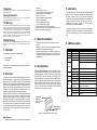
Trademarks
Contents subject to revision without prior notice.
property of their owners.
All other trademarks remain the
Copyright Statement
This publication may not be reproduced as a whole or in part, in any way whatsoever
unless prior consent has been obtained from the owner
FCC Warning
The Media Converter has been tested and found to comply with the limits for a Class A
digital device, pursuant to Part 15 of the FCC Rules. These standards are designed to
provide reasonable protection against harmful interference when this device is operated
in a commercial environment. This device generates, uses, and can radiate radio
frequency energy and may cause harmful interference to radio communications unless
installed in accordance with this User’s Guide. Operation of this device in a residential
area is likely to cause harmful interference which will make the user responsible for the
appropriate remedial action at his / her own expense.
CE Mark Warning
This is a Class A product. In a domestic environment this product may cause radio
interference in which case the user will need to consider adequate preventative
methods.
-
The package should contain the following items:
-
Media Converter
User’s Guide
Please notify your sales representative immediately if any item is
missing or damaged.
2. Overview
This Media Converter supports IEEE802.3at PoE feature and is
specifically designed to supply power to PoE-enabled devices
such as WiFi AP or surveillance cameras. It is a power supply
equipment (PSE) that can transmit data and supply power at the
same time to the powered devices (PD). The maximum cable
distance that can reach the powered devices from the Media
Converter is up to 80M, allowing your powered devices to be
installed in a place where power is not easily accessible.
Besides, this Media Converter aims at industrial applications that
demand wide range of operating temperature and require
redundant power supplies to create a reliable and stable
networking environment in the event of power failure. It can also
be mounted on the wall or onto 35mm DIN rail using DIN rail clip
on the media converter. The installation and operation procedures
are simple and straightforward. Operation status can be locally
monitored through a set of diagnostic LED indicators located on
the front panel.
-
-
Attach fiber cable from the Media Converter to the fiber
network.
Attach a UTP cable from the 10/100/1000Base-TX network
to the RJ-45 port on the Media Converter.
Connect the power adapter to the Media Converter and
check that the Power LED lights up. The TP Link/ACT and
F/O Link/ACT LED will light when all the cable connections
are satisfactory.
4. Terminal Block
-
Support IEEE 802.3, 802.3u, 802.3ab, 802.3z, 802.3x, 802.3at
Link Alarm allows users to easily identify and diagnose the linking
status. TP and F/O can link up only when both linking conditions
are good. In addition, if the TP or F/O port link is down during
operation, the other port will also be turned down to alert the user.
Setting Link Alarm DIP switch to Enable gives the user a
transparent link indication between two network devices
interconnected by the Media Converter.
If Link Alarm is disabled, the TP and F/O will link up based on their
individual linking condition. Furthermore, if either port link (TP or
F/O) is down during operation, it will not turn down the other port
link.
6. LED Description
LED
Color
PW ADC
PW T1
PW T2
TP
Link/ACT
Green
Green
Green
Green
Green Blinking
Off
Green
Orange
Green/Orange
Blinking
Off
Green
Green
Green Blinking
Speed
TB1 and TB2 Power Supply: There are two pairs of power
supply connection (TB1 and TB2) on the terminal block for power
redundancy purpose. You can use both pairs of power supply
(TB1 and TB2) or use either one pair of power supply on the
terminal block and AC external power supply to create redundant
setup. The redundant power supply will take over seamlessly
when one power source is down to protect your device or
network from the loss of power. When you use only one power
supply (no redundant power is available), the LED Power/Port
Status will flash in orange to alert the user.
FDX
F/O
Link/ACT
PWR/Port
Status
PoE
Use flat-head
screwdriver to
loosen and tighten
the screw.
Insert positive or
negative wire as
indicated.
Figure 1. Terminal Block Front and Top View
Major Features:
5. Link Alarm
3. Network Installation
-
1. Checklist
standards
Auto-Negotiation in TP port
Store and Forward Switching Mechanism
Support MDI/MDIX Auto-Crossover
Support Flow Control
Support fault alarms for power failures
Support 1K MAC address
Support 9K bytes Jumbo Frame
Support 32k bytes Memory Buffer
Support redundant AC and DC power supply
o
o
Support wide range of operating temperature (-20 C~60 C)
Support DIN Rail and Wall Mounting
Function
AC or DC power is available.
Terminal Block 1 powers up.
Terminal Block 2 powers up.
TP link is up.
TP is receiving and transmitting data.
Link is down or TP works in 10M.
TP works in 100M.
TP works in 1000M.
TP is receiving and transmitting data.
TP port works in half duplex mode.
TP port works in full duplex mode.
F/O link is up.
F/O is receiving and transmitting data.
TP or F/O link is down. (This indication only
Orange
works when DIP 8 and 9 are set to Enable.)
Orange
Redundancy system is abnormal (only one
Blinking
power source is available).
Green
Device provides power and works normally.
Green Blinking Device does not provide power.
Fast Green
Device’s PoE function is working
Blinking
abnormally.
7. Technical Specifications
Standards
Interface
9. Dimensions
Lantech
IEEE 802.3, 802.3u, 802.3ab, 802.3z,
802.3x, 802.3at
1 X 10/100/1000 RJ-45 connector
1 X 1000 SC F/O port or SFP slot
LED
PW ADC, PW T1, PW T2, TP Link/ACT, Speed,
FDX, F/O Link/ACT, PWR/Port Status, PoE
Power
DC Input Voltage: 48VDC
DC Terminal Block x 2
Shipping Weight
Dimensions
Temperature
Humidity
EMC Safety
Media
Metal Housing: 0.5KG
o
o
o
o
Operating: -20 C~60 C; Storage: -20 C~70 C
5%~90% RH non-condensing
FCC Part 15 Class A, CE
TP:
Fiber: EIA/TIA-568 CAT 5e
Fiber:
IPGC-0101GB
10/100/1000Base-T to 1000Base-X
Gigabit Ethernet Media Converter
with Built-in IEEE 802.3at PoE/PSE
Feature
50/125, 62.5/125um multi-mode fiber
9/125, 10/125um single-mode fiber
8. Recommendation for Shielded
network cables
STP cables have additional shielding material that is used to
reduce external interference. The shield also reduces the
emission at any point in the path of the cable. Our
recommendation is to deploy an STP network cable in
demanding electrical environments. Examples of demanding
indoor environments are where the network cable is located in
parallel with electrical mains supply cables or where large
inductive loads such as motors or contactors are in close vicinity
to the camera or its cable. It is also mandatory to use an STP
cable where the power device (like IP camera) is used outdoors
or where the network cable is routed outdoors.
User’s Guide
Version 1.6